You are not logged in.
- Topics: Active | Unanswered
Announcement
#51 2025-04-29 09:00:27
- kbd512
- Administrator
- Registered: 2015-01-02
- Posts: 8,519
Re: Heat Shield Design Manufacture Application Maintenance
tahanson43206,
AVCOAT is NOT a structural material. It's density is about 33lbs/ft^3 and thickness of material to protect Orion ranges between 1 inch (2.75lbs/ft^2) to 2 inches (5.5lbs/ft^2) areal density. 5.5lbs/ft^2 is already above the typical wing loading of an ultra-light, and so falls outside the range which keeps peak heating values low enough for practical reuse. To structurally support the AVCOAT heat shield, you must have a stiff and strong metallic or composite backing structure, as was/is the case for all AVCOAT heat shields from Gemini to Orion.
If the AVCOAT material itself is 2 inches thick, then it's 26.85kg/m^2, so already well above an ultra-light-like wing loading of 18.3kg/m^2. The point is that you're already beyond ultra-light-like wing loading BEFORE any structural backing material is added, never mind payload mass. Unfortunately, 2 inches of AVCOAT is only sufficient for 1 reentry from interplanetary velocities (moon, Mars, Venus). If you go any thicker or heavier to plausibly achieve multiple reuses without extensive refurbishment, then you're well above your mass per unit area limit necessary to knock-down those peak heating temperatures so that AVCOAT's ablation rate remains tolerable. In short, you must have a TPS with a much lower areal density, preferably structural in nature as is the case with HIAD and ADEPT, so you get some usable payload mass per unit area.
Optimum stiffener arrangement of hot structure HIAD rigid nose. The areal density of the ablative TPS design was 8.53 kg/m2 and the area density for the hot structure design was 10.07 kg/m2. This corresponds to a 15% increase in areal weight for the hot structure design as compared to the ablative TPS design.
HIAD and ADEPT are structural TPS materials / designs that are UNDER the areal density limit for achieving ultra-light-like wing loadings of 18.3kg/m^2. Anything heavier and non-structural in nature is going to weigh more than that per unit area, and thus increase peak heating rates to the point where ablation becomes significant. HIAD and ADEPT designs have been modeled that could withstand an interplanetary aerobraking maneuver, swiftly followed by EDL before the hot structure cools and becomes structurally unsound. My prior post in this thread included a paper on this, from NASA, from the group working on reusable / lightweight / deployable reentry heat shield technologies.
The reusable AVCOAT heat shield design doubled-up the thickness to achieve that outcome, and then they scraped away the charred material from the heat shield (after the protected vehicle was back on Earth) to retain its aerodynamic qualities for a subsequent reentry. That's one form of reusability that comes at the cost of additional mass per unit area.
Offline
Like button can go here
#52 2026-04-11 18:19:15
- tahanson43206
- Moderator
- Registered: 2018-04-27
- Posts: 24,306
Re: Heat Shield Design Manufacture Application Maintenance
This post is offered as a reminder that we have a topic for heat shields.
Heat shields are back in the news because Artemis II returned safely from the Moon using a heat shield that was NOT manufactured to the specifications of the Apollo heat shields.
As of April 11, 2026, news of how the heat shield performed is not yet made public.
There is potential for a company to specialize in Apollo style heat shields for the expected deep space traffic of future decades.
GW Johnson has described a way to make Apollo style heat shields without using individual squirt guns to fill thousands of hexagonal cells.
There should be enough return-from-deep-space business to support at least one company and perhaps more than one.
Of course, using the atmosphere to reduce velocity is NOT a good idea, if the destination planet is Earth, because of the clutter in LEO.
GW Johnson has described a system of Space Tugs that can match orbit with arriving vessels and put them in a LEO orbit with a bit of maneuvering.
(th)
Offline
Like button can go here
#53 2026-04-12 09:10:09
- GW Johnson
- Member
- From: McGregor, Texas USA
- Registered: 2011-12-04
- Posts: 6,199
- Website
Re: Heat Shield Design Manufacture Application Maintenance
Avcoat is a thick, not-quite-liquid, paste that is more like a dry mortar or cement material, comprised of epoxy-novolac polymer heavily loaded with silica fiber and phenolic microballoons. The polymer contribute the carbon to the char layer, with the silica fibers contributing some silica content. But the char is largely porous amorphous carbon. I do not know the standard percentages of the components, but I do know they can vary, especially the microballoon content. Porous amorphous carbon char handles to the touch about like a piece of charcoal from the BBQ grill that is burnt-through but not yet consumed to ash.
The microballoons contribute the porosity required to get the pyrolysis gases out from the pyrolyzing layer through the char. That is a serious issue in inch-plus thicknesses, not very much in fractional-inch thicknesses. And that is because the lower the permeability letting the gas out, the higher the driving gas pressure must be, to get out. And carbonaceous char is a very structurally weak material, especially in tensional loadings.
The microballoons lower the density, to around sp.gr = 0.51, instead of slightly greater than 1. That also increases the ablation rate (which is both pyrolysis and erosion of the char from the surface as fine grit). Higher microballoon content is lower density, higher ablation rate, and higher char permeability. It's a tradeoff, and can be varied from place to place on the heat shield, if desired.
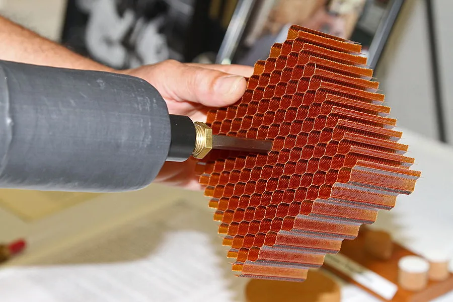
The heat shield on Apollo and on Orion EFT-1 was hand-gunned with what amounts to an air-powered caulking gun into each and every cell of a fiberglass hex bonded to the capsule structure. I think it was probably fiberglass-phenolic, but I do not know for sure that it was phenolic. I am sure of the fiberglass. These cells are on the order of at most hlf an inch in dimension. There were almost 300,000 of them on Apollo, and nearly 400,000 of them on Orion, in part because the lateral sides also needed the protection. That glass fiber hex reinforcement provides tensile strength to retain char from breaking off, and acts to limit cracks propagating from cell to cell.
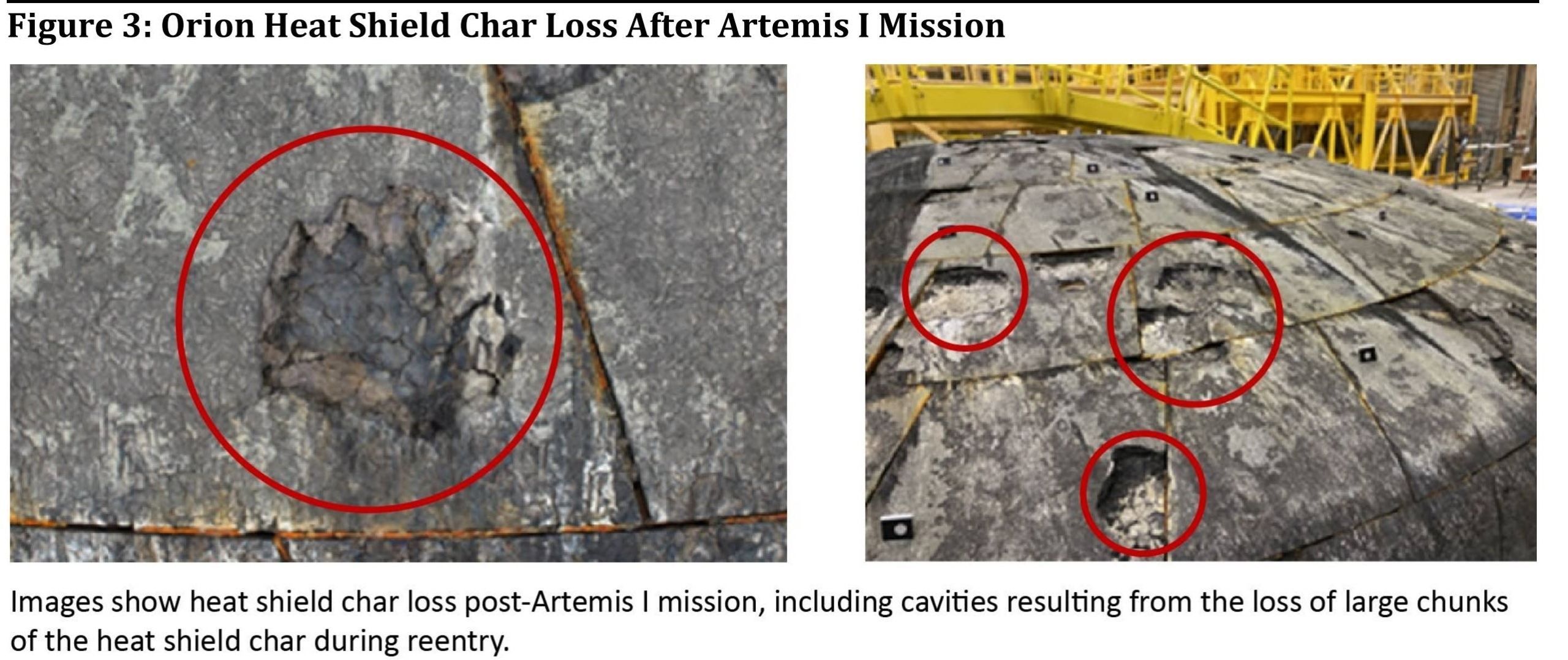
The enormous time and cost of the hand-gunning is why they decided to cast Avcoat blocks and machine precision tils from them. These were bonded to the capsule structure the way that PICA or PICA-X tiles would be bonded. The bonds and gap-fillers worked fine on Artemis-1, but the retention of the char did not. Without the reinforcing hex to hold it down and limit crack spread, several large chunks and bunch of small ones spalled off during that entry. Complicating that was this was a skip entry, with 2 heating pulses separated by a modest cooldown. A lot of these materials, particularly silica, suffer a solid phasa change at about 2300 F that causes shrinkage by around 3%, and embrittlement to the point of no strength at all: they just crumble at a touch.
That hex-reinforced Avcoat worked just fine on every Apollo and that Orion EFT-1. Something similar flew on Gemini with the hex cell thing on only the heat shield (the lateral sides were bare superalloy), but the polymer was a Dow Corning silicone, and I do not know what solids it was loaded with.
The problem was that Artemis-2's heat shield was built and shipped for assembly before Artemis-1 ever flew. The spalling of chunks caught everyone by surprise. Their thermo-structural models and arc jet data did not predict this. So was it the lack of hex, or the two-heating pulse skip? NASA spent a year convincing its management that it was the skip, so they flew Artemis-2 back with almost no skip at all.
Myself, I think it's actually both effects. They need to put the hex into the tiles, but they need to do it without hand-gunning, or they might as well go back to the Apollo and Orion EFT-1 technique. I figured out a way to load all the cells at once in a chunk of hex, using an extrusion press, in order to make hex reinforced blocks for machining the bonded tiles. And I gave that to NASA, although so far they have ignored me.
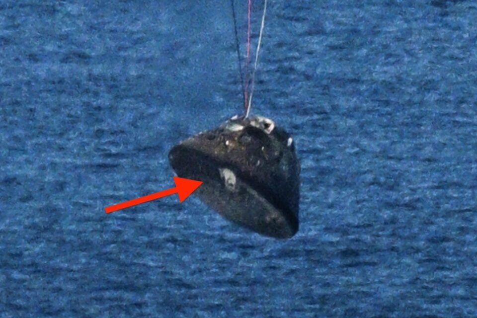
I have seen one blurry photo of Artemis-2 being hoisted out of the sea. Everybody comments on the weird-looking but expected damage near one of the four hold-down pads. I thought I saw some missing-chunk craters, fewer and smaller than Artemis-1, but there! But, the photo was blurry, so I as-yet know nothing for-sure! I did see some localized outer-layer burn-through damages on the lateral side, low down, close to the heat shield, in some of the photos of the crew standing next to it. The Avcoat is very thin there.
GW
Last edited by GW Johnson (2026-04-12 10:00:42)
GW Johnson
McGregor, Texas
"There is nothing as expensive as a dead crew, especially one dead from a bad management decision"
Offline
Like button can go here
#54 2026-04-12 13:21:07
- SpaceNut
- Administrator
- From: New Hampshire
- Registered: 2004-07-22
- Posts: 30,700
Re: Heat Shield Design Manufacture Application Maintenance
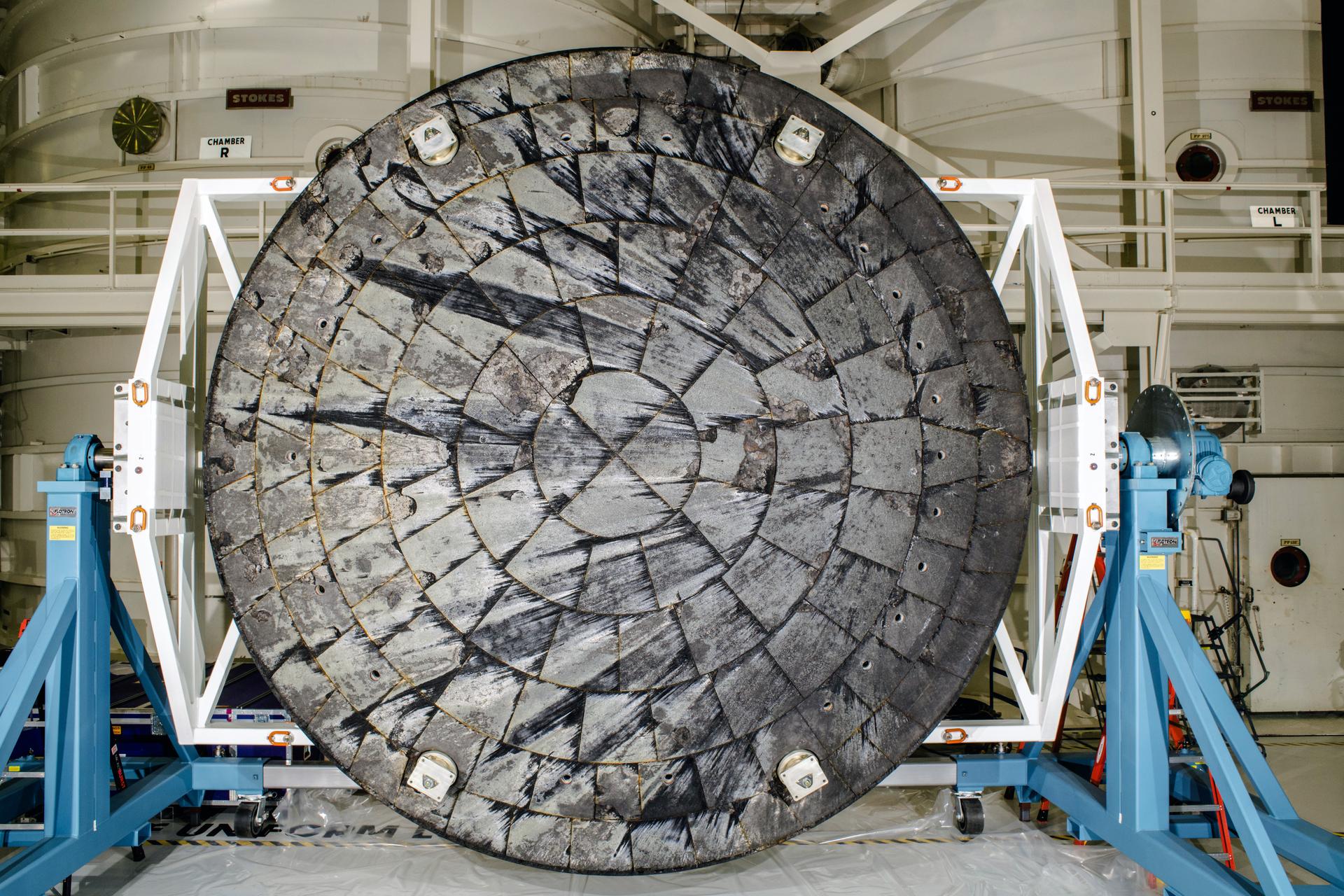
The is the outside view of the shield before installation

The view of the under side facing towards the capsule which was not changed from 1 or 2 flight.

Nasa is blaming the shield was due to
The bondline is critical — Artemis I’s unexpected erosion was partly linked to bondline behavior under uneven heating.
small leveling differences between blocks that altered local heating and gas flow.
as GW has mentioned for the method of how its made edit back in the Apollo era
this was not artemis used
Avcoat Block Composition
Each block is a reformulated version of Avcoat 5026‑39, an epoxy‑novolac resin with silica microballoons and fibers.
The blocks are:
Designed to char, ablate, and carry heat away
Densified to a specific target density
Coated with a thin sealant to control moisture and handling damage
NASA discovered after Artemis I that over‑dense blocks trapped pyrolysis gases, contributing to the “pockmark” blow‑outs.
Artemis II blocks were manufactured with slightly reduced density to allow gas venting.
broad view of the shield after number 1's entry
what you did not see in that view
The view of artemis 2 before install

Artemis I → Artemis II Modifications
NASA did not redesign the heat shield for Artemis II.
Instead, they:
Adjusted Avcoat density
Improved block‑leveling tolerances
Refined application process
Altered the reentry trajectory to reduce peak heating
Edit to correct assumptions
Machines blocks, gap fillers, adhesives, bolting to the frame that you see on the underside, is the reason for the char
Offline
Like button can go here
#55 2026-04-12 15:18:44
- GW Johnson
- Member
- From: McGregor, Texas USA
- Registered: 2011-12-04
- Posts: 6,199
- Website
Re: Heat Shield Design Manufacture Application Maintenance
With Spacenut's photo of the fiberglass hex with the hand-gun tool inserted, I an now sure that the hex's resin was phenolic. I saw a lot of electrical and electronic board materials in the 60's and 70's made of this very same stuff. The color is the key to identifying it: that orange is commercial phenolic resin, on plain white fiberglass cloth. Cures at modest heat and only some pressure between mold platens, if you are making flat panels. I do not know what tooling was used to make hex.
The type of phenolic that went into the glass and silica phenolic materials was different! It cures under greater heat and a lot of pressure, and is tan in color. I used a lot of silica phenolic in ramjet nozzles, and in rocket nozzle assemblies. It is tough, dense, slow-ablating, and very heavy. The fiber is in woven cloth form, and you must be very careful to orient the cloth layers correctly relative to the flow direction.
GW
Last edited by GW Johnson (2026-04-12 15:20:53)
GW Johnson
McGregor, Texas
"There is nothing as expensive as a dead crew, especially one dead from a bad management decision"
Offline
Like button can go here
#56 2026-04-12 17:18:14
- SpaceNut
- Administrator
- From: New Hampshire
- Registered: 2004-07-22
- Posts: 30,700
Re: Heat Shield Design Manufacture Application Maintenance
fixed some content in last post
Offline
Like button can go here
#57 Yesterday 07:56:40
- tahanson43206
- Moderator
- Registered: 2018-04-27
- Posts: 24,306
Re: Heat Shield Design Manufacture Application Maintenance
These images show the bottom of the Artemis II heat shield shortly after it was hoisted out of the water by the US Navy recovery ship.
Close up of fixture to hold Orion to service module
Apollo 11 heat shield for comparison
For all ... there are likely to be many images and reports developed from the Artemis II flight.
This topic is a good place for heat shield images and reports.
We have a topic for Artemis II reports. Search for topics with Artemis in the title.
(th)
Offline
Like button can go here
#58 Yesterday 14:25:51
- SpaceNut
- Administrator
- From: New Hampshire
- Registered: 2004-07-22
- Posts: 30,700
Re: Heat Shield Design Manufacture Application Maintenance
To fix the problem ahead of the crewed Artemis 2 mission, NASA engineers opted to modify Orion’s skip-entry trajectory rather than altering the heat shield’s design. This, in theory, would allow the outer layer to “breathe” throughout reentry, preventing gas buildup and cracking.

Offline
Like button can go here
#59 Yesterday 16:00:09
- GW Johnson
- Member
- From: McGregor, Texas USA
- Registered: 2011-12-04
- Posts: 6,199
- Website
Re: Heat Shield Design Manufacture Application Maintenance
I think the closeup photo is an enhanced version with clearer focus, but a reduced view dimension, of the blurry photo that shows the whole capsule.
I an not at all sure this has anything to do with being "hoisted up". I suspect without proof the blurry photo was taken just before splashdown, still hanging from the main chutes.
Take a good look at the clearer restricted-view photo. This was intended to show the damage near one attachment pad that did not survive. That is what the whitish "stain" is, staining from the melting metal. There is extra erosion there, too.
But, look up at the lateral side near that same place. Do you, or do you not, see exposed and distorted metal, and maybe a burn-through, where the lateral-side heat tiles were thinner? Maybe too thin? Those whitish areas are not windows, they are exposed locations of the metal outer shell to which the heat shield tiles were attached.
GW
Last edited by GW Johnson (Yesterday 16:10:13)
GW Johnson
McGregor, Texas
"There is nothing as expensive as a dead crew, especially one dead from a bad management decision"
Offline
Like button can go here