New Mars Forums
You are not logged in.
- Topics: Active | Unanswered
Announcement
#51 2025-04-29 09:00:27
- kbd512
- Administrator
- Registered: 2015-01-02
- Posts: 8,533
Re: Heat Shield Design Manufacture Application Maintenance
tahanson43206,
AVCOAT is NOT a structural material. It's density is about 33lbs/ft^3 and thickness of material to protect Orion ranges between 1 inch (2.75lbs/ft^2) to 2 inches (5.5lbs/ft^2) areal density. 5.5lbs/ft^2 is already above the typical wing loading of an ultra-light, and so falls outside the range which keeps peak heating values low enough for practical reuse. To structurally support the AVCOAT heat shield, you must have a stiff and strong metallic or composite backing structure, as was/is the case for all AVCOAT heat shields from Gemini to Orion.
If the AVCOAT material itself is 2 inches thick, then it's 26.85kg/m^2, so already well above an ultra-light-like wing loading of 18.3kg/m^2. The point is that you're already beyond ultra-light-like wing loading BEFORE any structural backing material is added, never mind payload mass. Unfortunately, 2 inches of AVCOAT is only sufficient for 1 reentry from interplanetary velocities (moon, Mars, Venus). If you go any thicker or heavier to plausibly achieve multiple reuses without extensive refurbishment, then you're well above your mass per unit area limit necessary to knock-down those peak heating temperatures so that AVCOAT's ablation rate remains tolerable. In short, you must have a TPS with a much lower areal density, preferably structural in nature as is the case with HIAD and ADEPT, so you get some usable payload mass per unit area.
Optimum stiffener arrangement of hot structure HIAD rigid nose. The areal density of the ablative TPS design was 8.53 kg/m2 and the area density for the hot structure design was 10.07 kg/m2. This corresponds to a 15% increase in areal weight for the hot structure design as compared to the ablative TPS design.
HIAD and ADEPT are structural TPS materials / designs that are UNDER the areal density limit for achieving ultra-light-like wing loadings of 18.3kg/m^2. Anything heavier and non-structural in nature is going to weigh more than that per unit area, and thus increase peak heating rates to the point where ablation becomes significant. HIAD and ADEPT designs have been modeled that could withstand an interplanetary aerobraking maneuver, swiftly followed by EDL before the hot structure cools and becomes structurally unsound. My prior post in this thread included a paper on this, from NASA, from the group working on reusable / lightweight / deployable reentry heat shield technologies.
The reusable AVCOAT heat shield design doubled-up the thickness to achieve that outcome, and then they scraped away the charred material from the heat shield (after the protected vehicle was back on Earth) to retain its aerodynamic qualities for a subsequent reentry. That's one form of reusability that comes at the cost of additional mass per unit area.
Offline
Like button can go here
#52 2026-04-11 18:19:15
- tahanson43206
- Moderator
- Registered: 2018-04-27
- Posts: 25,471
Re: Heat Shield Design Manufacture Application Maintenance
This post is offered as a reminder that we have a topic for heat shields.
Heat shields are back in the news because Artemis II returned safely from the Moon using a heat shield that was NOT manufactured to the specifications of the Apollo heat shields.
As of April 11, 2026, news of how the heat shield performed is not yet made public.
There is potential for a company to specialize in Apollo style heat shields for the expected deep space traffic of future decades.
GW Johnson has described a way to make Apollo style heat shields without using individual squirt guns to fill thousands of hexagonal cells.
There should be enough return-from-deep-space business to support at least one company and perhaps more than one.
Of course, using the atmosphere to reduce velocity is NOT a good idea, if the destination planet is Earth, because of the clutter in LEO.
GW Johnson has described a system of Space Tugs that can match orbit with arriving vessels and put them in a LEO orbit with a bit of maneuvering.
(th)
Offline
Like button can go here
#53 2026-04-12 09:10:09
- GW Johnson
- Member
- From: McGregor, Texas USA
- Registered: 2011-12-04
- Posts: 6,260
- Website
Re: Heat Shield Design Manufacture Application Maintenance
Avcoat is a thick, not-quite-liquid, paste that is more like a dry mortar or cement material, comprised of epoxy-novolac polymer heavily loaded with silica fiber and phenolic microballoons. The polymer contribute the carbon to the char layer, with the silica fibers contributing some silica content. But the char is largely porous amorphous carbon. I do not know the standard percentages of the components, but I do know they can vary, especially the microballoon content. Porous amorphous carbon char handles to the touch about like a piece of charcoal from the BBQ grill that is burnt-through but not yet consumed to ash.
The microballoons contribute the porosity required to get the pyrolysis gases out from the pyrolyzing layer through the char. That is a serious issue in inch-plus thicknesses, not very much in fractional-inch thicknesses. And that is because the lower the permeability letting the gas out, the higher the driving gas pressure must be, to get out. And carbonaceous char is a very structurally weak material, especially in tensional loadings.
The microballoons lower the density, to around sp.gr = 0.51, instead of slightly greater than 1. That also increases the ablation rate (which is both pyrolysis and erosion of the char from the surface as fine grit). Higher microballoon content is lower density, higher ablation rate, and higher char permeability. It's a tradeoff, and can be varied from place to place on the heat shield, if desired.
The heat shield on Apollo and on Orion EFT-1 was hand-gunned with what amounts to an air-powered caulking gun into each and every cell of a fiberglass hex bonded to the capsule structure. I think it was probably fiberglass-phenolic, but I do not know for sure that it was phenolic. I am sure of the fiberglass. These cells are on the order of at most hlf an inch in dimension. There were almost 300,000 of them on Apollo, and nearly 400,000 of them on Orion, in part because the lateral sides also needed the protection. That glass fiber hex reinforcement provides tensile strength to retain char from breaking off, and acts to limit cracks propagating from cell to cell.
The enormous time and cost of the hand-gunning is why they decided to cast Avcoat blocks and machine precision tils from them. These were bonded to the capsule structure the way that PICA or PICA-X tiles would be bonded. The bonds and gap-fillers worked fine on Artemis-1, but the retention of the char did not. Without the reinforcing hex to hold it down and limit crack spread, several large chunks and bunch of small ones spalled off during that entry. Complicating that was this was a skip entry, with 2 heating pulses separated by a modest cooldown. A lot of these materials, particularly silica, suffer a solid phasa change at about 2300 F that causes shrinkage by around 3%, and embrittlement to the point of no strength at all: they just crumble at a touch.
That hex-reinforced Avcoat worked just fine on every Apollo and that Orion EFT-1. Something similar flew on Gemini with the hex cell thing on only the heat shield (the lateral sides were bare superalloy), but the polymer was a Dow Corning silicone, and I do not know what solids it was loaded with.
The problem was that Artemis-2's heat shield was built and shipped for assembly before Artemis-1 ever flew. The spalling of chunks caught everyone by surprise. Their thermo-structural models and arc jet data did not predict this. So was it the lack of hex, or the two-heating pulse skip? NASA spent a year convincing its management that it was the skip, so they flew Artemis-2 back with almost no skip at all.
Myself, I think it's actually both effects. They need to put the hex into the tiles, but they need to do it without hand-gunning, or they might as well go back to the Apollo and Orion EFT-1 technique. I figured out a way to load all the cells at once in a chunk of hex, using an extrusion press, in order to make hex reinforced blocks for machining the bonded tiles. And I gave that to NASA, although so far they have ignored me.
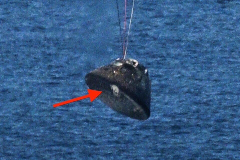
I have seen one blurry photo of Artemis-2 being hoisted out of the sea. Everybody comments on the weird-looking but expected damage near one of the four hold-down pads. I thought I saw some missing-chunk craters, fewer and smaller than Artemis-1, but there! But, the photo was blurry, so I as-yet know nothing for-sure! I did see some localized outer-layer burn-through damages on the lateral side, low down, close to the heat shield, in some of the photos of the crew standing next to it. The Avcoat is very thin there.
GW
Last edited by GW Johnson (2026-04-12 10:00:42)
GW Johnson
McGregor, Texas
"There is nothing as expensive as a dead crew, especially one dead from a bad management decision"
Offline
Like button can go here
#54 2026-04-12 13:21:07
- SpaceNut
- Administrator
- From: New Hampshire
- Registered: 2004-07-22
- Posts: 30,828
Re: Heat Shield Design Manufacture Application Maintenance
The is the outside view of the shield before installation
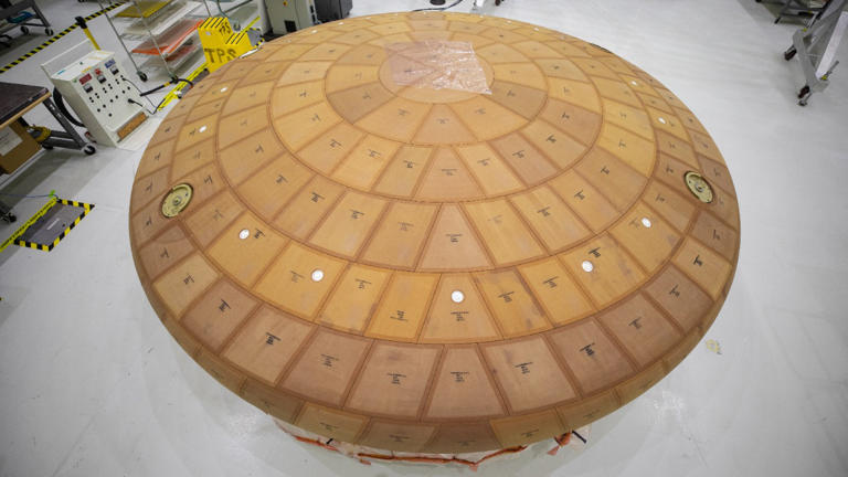
The view of the under side facing towards the capsule which was not changed from 1 or 2 flight.

Nasa is blaming the shield was due to
The bondline is critical — Artemis I’s unexpected erosion was partly linked to bondline behavior under uneven heating.
small leveling differences between blocks that altered local heating and gas flow.
as GW has mentioned for the method of how its made edit back in the Apollo era
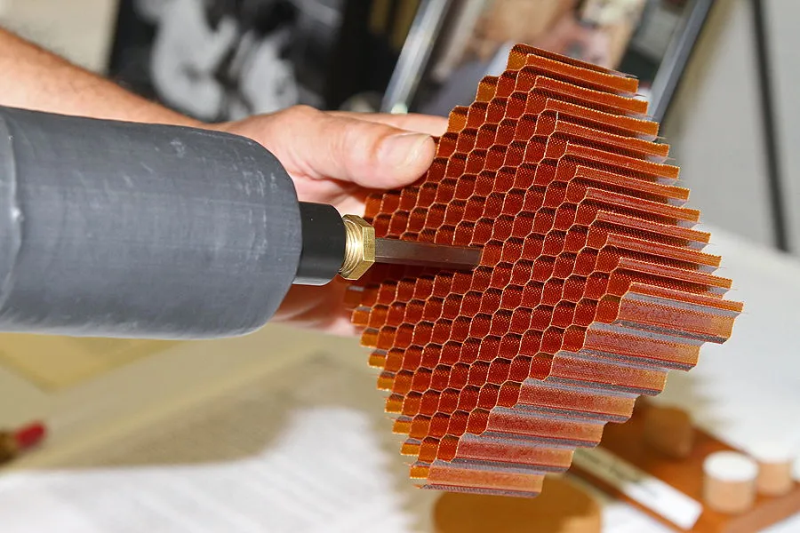
this was not artemis used
Avcoat Block Composition
Each block is a reformulated version of Avcoat 5026‑39, an epoxy‑novolac resin with silica microballoons and fibers.
The blocks are:
Designed to char, ablate, and carry heat away
Densified to a specific target density
Coated with a thin sealant to control moisture and handling damage
NASA discovered after Artemis I that over‑dense blocks trapped pyrolysis gases, contributing to the “pockmark” blow‑outs.
Artemis II blocks were manufactured with slightly reduced density to allow gas venting.
broad view of the shield after number 1's entry
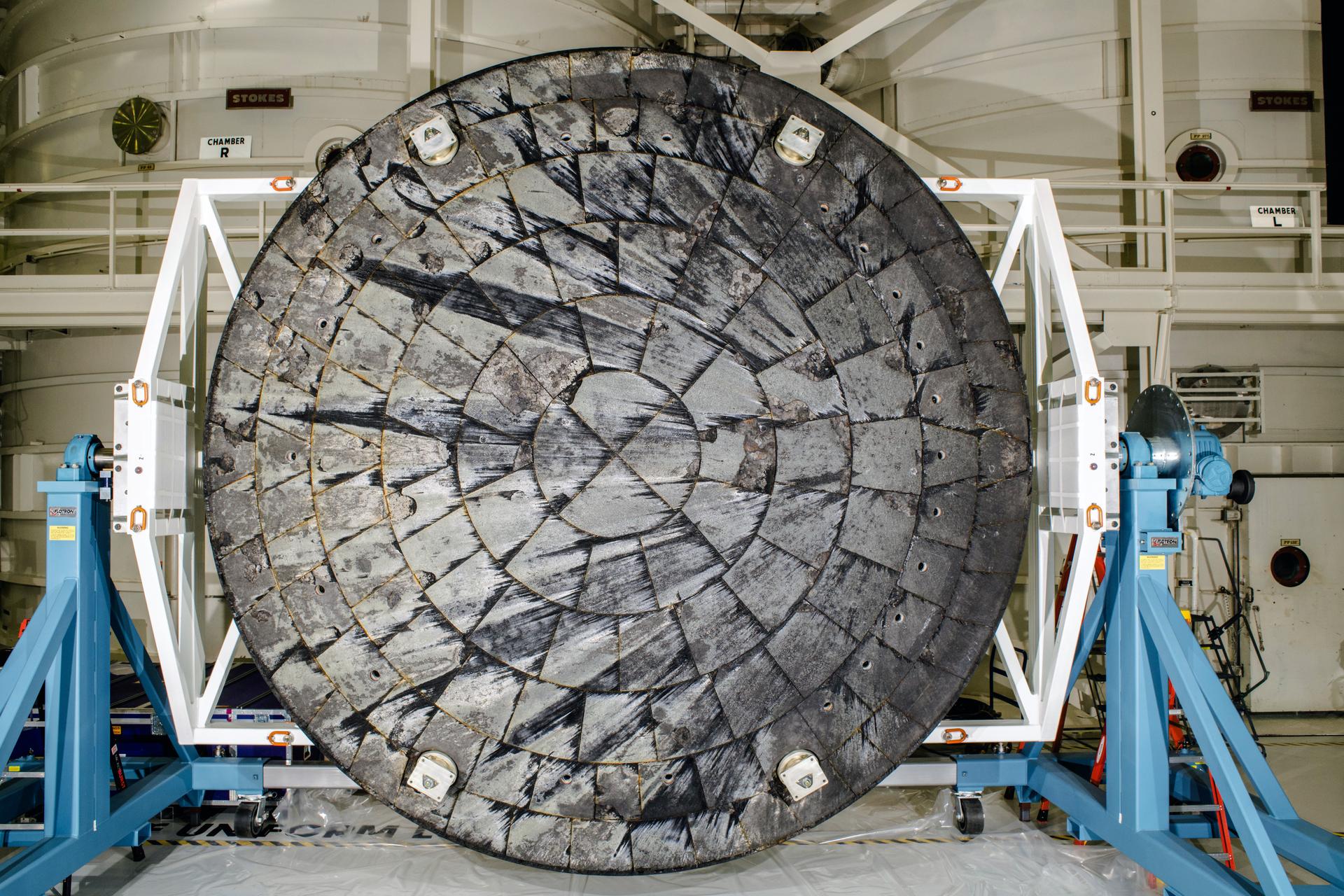
what you did not see in that view
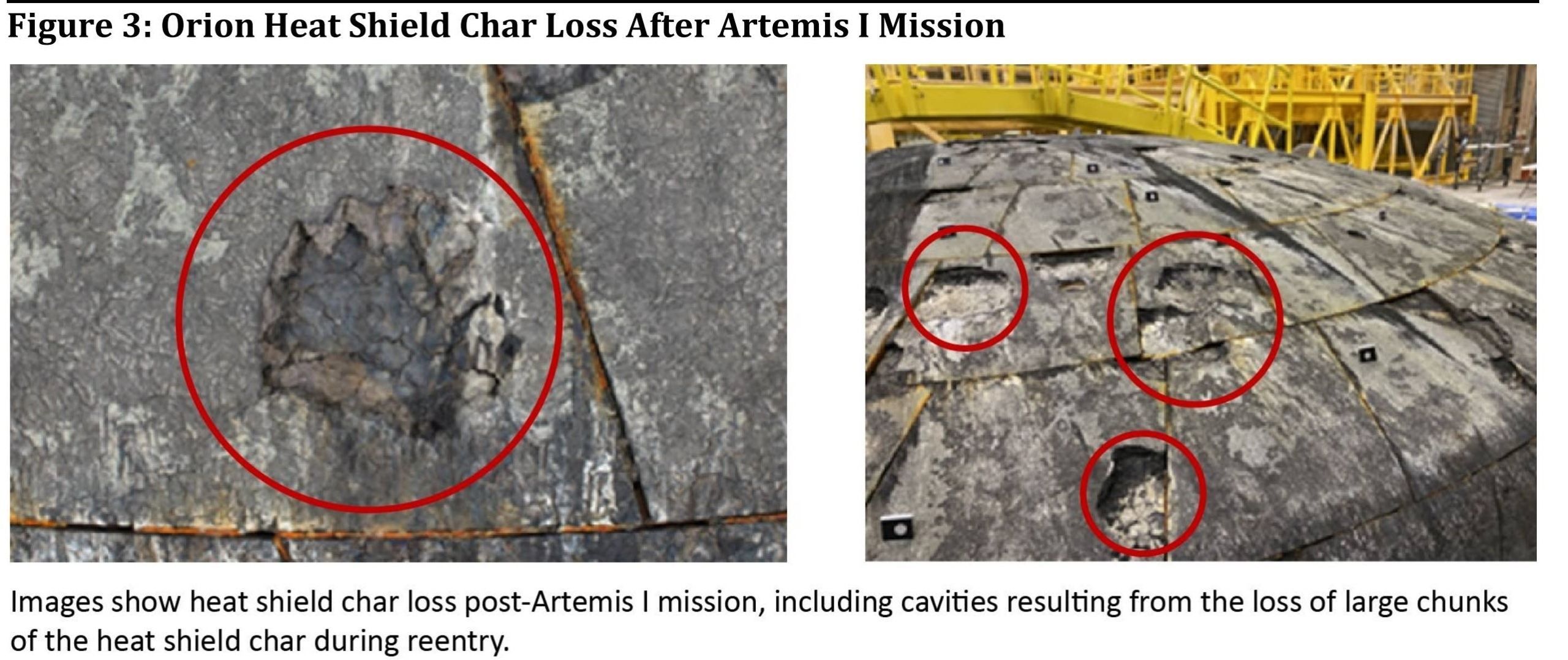
The view of artemis 2 before install

Artemis I → Artemis II Modifications
NASA did not redesign the heat shield for Artemis II.
Instead, they:
Adjusted Avcoat density
Improved block‑leveling tolerances
Refined application process
Altered the reentry trajectory to reduce peak heating
Edit to correct assumptions
Machines blocks, gap fillers, adhesives, bolting to the frame that you see on the underside, is the reason for the char
Offline
Like button can go here
#55 2026-04-12 15:18:44
- GW Johnson
- Member
- From: McGregor, Texas USA
- Registered: 2011-12-04
- Posts: 6,260
- Website
Re: Heat Shield Design Manufacture Application Maintenance
With Spacenut's photo of the fiberglass hex with the hand-gun tool inserted, I an now sure that the hex's resin was phenolic. I saw a lot of electrical and electronic board materials in the 60's and 70's made of this very same stuff. The color is the key to identifying it: that orange is commercial phenolic resin, on plain white fiberglass cloth. Cures at modest heat and only some pressure between mold platens, if you are making flat panels. I do not know what tooling was used to make hex.
The type of phenolic that went into the glass and silica phenolic materials was different! It cures under greater heat and a lot of pressure, and is tan in color. I used a lot of silica phenolic in ramjet nozzles, and in rocket nozzle assemblies. It is tough, dense, slow-ablating, and very heavy. The fiber is in woven cloth form, and you must be very careful to orient the cloth layers correctly relative to the flow direction.
GW
Last edited by GW Johnson (2026-04-12 15:20:53)
GW Johnson
McGregor, Texas
"There is nothing as expensive as a dead crew, especially one dead from a bad management decision"
Offline
Like button can go here
#56 2026-04-12 17:18:14
- SpaceNut
- Administrator
- From: New Hampshire
- Registered: 2004-07-22
- Posts: 30,828
Re: Heat Shield Design Manufacture Application Maintenance
fixed some content in last post
Offline
Like button can go here
#57 2026-04-13 07:56:40
- tahanson43206
- Moderator
- Registered: 2018-04-27
- Posts: 25,471
Re: Heat Shield Design Manufacture Application Maintenance
These images show the bottom of the Artemis II heat shield shortly after it was hoisted out of the water by the US Navy recovery ship.
Close up of fixture to hold Orion to service module
Apollo 11 heat shield for comparison
For all ... there are likely to be many images and reports developed from the Artemis II flight.
This topic is a good place for heat shield images and reports.
We have a topic for Artemis II reports. Search for topics with Artemis in the title.
(th)
Offline
Like button can go here
#58 2026-04-13 14:25:51
- SpaceNut
- Administrator
- From: New Hampshire
- Registered: 2004-07-22
- Posts: 30,828
Re: Heat Shield Design Manufacture Application Maintenance
To fix the problem ahead of the crewed Artemis 2 mission, NASA engineers opted to modify Orion’s skip-entry trajectory rather than altering the heat shield’s design. This, in theory, would allow the outer layer to “breathe” throughout reentry, preventing gas buildup and cracking.

Offline
Like button can go here
#59 2026-04-13 16:00:09
- GW Johnson
- Member
- From: McGregor, Texas USA
- Registered: 2011-12-04
- Posts: 6,260
- Website
Re: Heat Shield Design Manufacture Application Maintenance
I think the closeup photo is an enhanced version with clearer focus, but a reduced view dimension, of the blurry photo that shows the whole capsule.
I an not at all sure this has anything to do with being "hoisted up". I suspect without proof the blurry photo was taken just before splashdown, still hanging from the main chutes.
Take a good look at the clearer restricted-view photo. This was intended to show the damage near one attachment pad that did not survive. That is what the whitish "stain" is, staining from the melting metal. There is extra erosion there, too.
But, look up at the lateral side near that same place. Do you, or do you not, see exposed and distorted metal, and maybe a burn-through, where the lateral-side heat tiles were thinner? Maybe too thin? Those whitish areas are not windows, they are exposed locations of the metal outer shell to which the heat shield tiles were attached.
GW
Last edited by GW Johnson (2026-04-13 16:10:13)
GW Johnson
McGregor, Texas
"There is nothing as expensive as a dead crew, especially one dead from a bad management decision"
Offline
Like button can go here
#60 2026-04-21 12:57:23
- tahanson43206
- Moderator
- Registered: 2018-04-27
- Posts: 25,471
Re: Heat Shield Design Manufacture Application Maintenance
The article at the link below shows the heat shield from under water after Artemis II "landed".
The article also reports rumors that the shield looked surprisingly good, but (of course) that may just be happy talk.
https://www.yahoo.com/news/articles/gue … 52753.html
Futurism
Guess What This Creepy Underwater Thing Is That Was Photographed by US Navy Divers for NASA
Victor Tangermann
Tue, April 21, 2026 at 11:20 AM EDT
3 min readAn intriguing photo shows the charred heat shield of NASA's Artemis 2 Orion capsule right after splashdown in the Pacific on April 10.
A photo shared by NASA shows the charred heat shield of the Artemis 2 Orion capsule after landing in the Pacific Ocean on April 10, following a successful crewed mission around the Moon.
It may look like the underwater remains of a church that’s been submerged for hundreds of years following a dam break, or a tunnel boring machine that just broke through a mound of rubble.
But if those were your guesses, you’d be sorely mistaken. An intriguing photo taken by US Navy divers and shared by NASA on Monday shows the charred heat shield of the space agency’s Artemis 2 Orion capsule, right after it took a plunge in the Pacific Ocean upon landing on April 10.
While the subsequent post flight analysis may drag on for quite some time, it’s an intriguing first glimpse at one of the more controversial aspects of NASA’s triumphant crewed return to the Moon. The tiled heat shield is designed to keep astronauts safe as their spacecraft slams into the Earth’s atmosphere at over 23,000 mph, a maneuver that causes it to heat up to thousands of degrees Fahrenheit.
A photo taken by US Navy divers and shared by NASA on Monday, showing the charred heat shield of the space agency's Artemis 2 Orion capsule right after it took a plunge in the Pacific Ocean upon landing on April 10.
During NASA’s inaugural 2022 Artemis 1 mission, which saw the Orion spacecraft travel around the Moon and back without a crew on board, the heat shield endured major damage upon reentry, including cracking and pieces of charred remains breaking off.
For comparison, the photo embedded below shows the significant damage the heat shield received following the Artemis 1 mission in 2022.
This photo shows the charred heat shield of the Orion capsule after NASA's uncrewed Artemis 1 mission.Ahead of the mission’s launch, several experts warned that flying the same design, albeit with an adjusted trajectory to minimize the amount of heat build-up, could put the crew of the Artemis 2 mission in danger. (The Artemis 2 heat shield was installed on the Orion capsule even before NASA launched Artemis 1.)
However, early impressions suggest the heat shield appears to have done a tremendous job in keeping the four astronauts safe this month. In other words, NASA’s plans to adjust the reentry path may have paid off, which bodes well for future Artemis missions, including Artemis 4, the first planned mission to the lunar surface, tentatively scheduled for 2028.
According to NASA, “the crew and spacecraft were safeguarded by Orion’s thermal protection system as they traveled nearly 35 times the speed of sound during reentry.”
“Initial inspections of the system found it performed as expected, with no unusual conditions identified,” the agency noted. “Diver imagery of the spacecraft’s heat shield initially taken after splashdown and further inspections on the recovery ship found the char loss behavior observed on Artemis I was significantly reduced, both in terms of quantity and size.”
Even reflective tape, designed to control vehicle temperatures in space, survived reentry in “numerous locations,” NASA noted.
The entire crew module will be returned to NASA’s Kennedy Space Center before the end of the month for “additional examination of the heat shield.” It will then be taken to the Marshall Space Flight Center for further testing, including “sample extraction and internal x-ray scans.”
Beyond the heat shield, NASA also noted that it would be carefully examining the capsule’s space toilet — which turned out to be a major pain point throughout the astronauts’ ten-day adventure around the Moon after frozen urine clogged up the commode’s vent lines.
“Teams will work to identify root cause and initiate corrective action for Artemis 3,” NASA vowed.
(th)
Offline
Like button can go here
#61 2026-04-26 15:03:52
- SpaceNut
- Administrator
- From: New Hampshire
- Registered: 2004-07-22
- Posts: 30,828
Re: Heat Shield Design Manufacture Application Maintenance
Shortly after Artemis II splashdown on Friday, April 10, 2026, U.S. Navy divers captured underwater imagery of the Orion spacecraft’s heat shield.
Offline
Like button can go here
#62 2026-04-28 12:20:49
- tahanson43206
- Moderator
- Registered: 2018-04-27
- Posts: 25,471
Re: Heat Shield Design Manufacture Application Maintenance
Here is a link to a paper by GW Johnson about the Artemis II heat shield.
The image shown by SpaceNut in post #61 is referenced.
https://newmars.com/forums/viewtopic.ph … 64#p239064
(th)
Offline
Like button can go here
#63 2026-07-29 09:57:21
- tahanson43206
- Moderator
- Registered: 2018-04-27
- Posts: 25,471
Re: Heat Shield Design Manufacture Application Maintenance
This post links to a post from the Starship topic:
https://newmars.com/forums/viewtopic.ph … 98#p240598
Dr. Johnson comments upon the difficulty of creating a heat shield that can survive multiple flights.
In 2026, no such heat shield exists.
(th)
Offline
Like button can go here
#64 2026-07-31 08:48:43
- tahanson43206
- Moderator
- Registered: 2018-04-27
- Posts: 25,471
Re: Heat Shield Design Manufacture Application Maintenance
In this post, we link to a PDF by Dr. Johnson on heat shields ...
https://www.dropbox.com/scl/fi/uihbh4yy … eemsd&dl=0
In this paper, GW examines what kind of material might be needed to address the Mars return problem.
(th)
Offline
Like button can go here
#65 2026-08-01 11:58:26
- tahanson43206
- Moderator
- Registered: 2018-04-27
- Posts: 25,471
Re: Heat Shield Design Manufacture Application Maintenance
This post is about a technology development that may help SpaceX to achieve their stated one-day vehicle turn-around objective.
Robot technology has advanced significantly since the NASA Space Shuttle flew. In the days of the NASA Space Shuttle, teams of humans had to inspect and repair the tiles under and around the Shuttle. That process took extended periods of time.
Now-a-days, SpaceX has the opportunity to enlist robotic inspectors and repair agents to operate simultaneously all over the underside of a Starship after a flight. If the gaps between tiles need fresh sealant the need material can be applied quickly and accurately.
Since SpaceX is right in the thick of robotics development, I think we can expect to see robotic solutions to the reflight process.
(th)
Offline
Like button can go here
#66 2026-08-03 06:39:55
- Void
- Member
- Registered: 2011-12-29
- Posts: 9,755
Re: Heat Shield Design Manufacture Application Maintenance
I liked your last post (th).
I want to do some elaborations here on my thinking on the matter.
But first a little bit of bitter examination: https://www.bing.com/videos/riverview/r … 0e0dbb3c83 Quote:
NASA's engineer just revealed Starship Heat Shield is “Dead End”. Elon Musk LAUGH...
YouTube
ALPHA TECH
6.5K views
I think they are right and wrong. Right that it is not ready to do all the things that have been on the wish list, but I think that they are wrong about the system being able to improve on LEO access.
I believe that the system can do better than the Space Shuttle.
It may not be as repeatable as the Falcon 9 1st stage yet. It may not be as cost effective as the Falcon 9 1st stage is now.
But I have some notions to float about all of this.
First of all if the ship had landed on the tower, and the Engines and Engine Support gear and many other parts are still in good shape, the ship could be reused again even without a heat shield. So that is to twice use the whole ship including the engines.
What about a multi-Body solution?
The ship can be divided into two sets of parts. 1) Main body with heat shield. 2) Accessories. (Engines Etc.).
I think that perhaps the issue is shelf life. Even if you put an engine on a shelf, over time it will deteriorate or become of an obsolete model.
So, then to justify its manufacture, the desire is to put it to work to pay the cost of manufacture.
(th) has mentioned a robotic system to inspect and repair the heat shield. I think this may be possible. They already create the heat shield robotically I believe.
Query: "Does SpaceX use a robotic system to build the heat shield on the Starship?" The answer seems to be yes.
https://www.bing.com/search?q=Does+Spac … pc=EDGEXST
Quote:
Copilot Search Branding
Like
Dislike
Yes — SpaceX does use robotic systems to help build and install the Starship heat shield.
So, I don't know can they repair a heat shield faster than and cheaper than was for the Space Shuttle? Probably, I think.
Query: "How long did it take to refurbish the Space Shuttle?" It needs to be remembered that the reuse of the Shuttle 1st stage never was practical as I recall. (Solid Rockets and Main Tank).
Quote:
For most operational missions, NASA aimed for a turnaround of about 6–12 months between flights 19FortyFive.
So, what if you could have 3 bodies and 1 set of accessories?
Accessories might be Engines and Engine support gear, and things like flap motors, maybe the flaps.
If you had two robot stations for each set of 3 bodies, perhaps each robot station could turn around a bodies heat shield in perhaps 2 weeks or a month.
Yes, it would be a lot of cost to move "Accessories" between a rotation of 3 bodies, but it might be worth it.
So, if your production factory could focus more on generating new ship bodies mostly of stainless steel and Heat Shields, you would not have to manufacture as many "Accessories".
No, this is not to fly every hour, maybe the Superheavy can get to that frequency, but the 3-body method might be the way to get partway to rapid reuse.
A way to get the value out of the "Accessories".
Ending Pending 
Last edited by Void (2026-08-03 07:12:22)
Be careful what you wish for.
Offline
Like button can go here
#67 2026-08-05 18:06:24
- SpaceNut
- Administrator
- From: New Hampshire
- Registered: 2004-07-22
- Posts: 30,828
Re: Heat Shield Design Manufacture Application Maintenance
Going to mars lands a heatshield for a starship shaped vehicle seems to require a second one put over the original for coming back to earth. That mass is not a problem from coming back from mars as we have dumped or used the payloads going or staying on mars. Its about what to make and add to be layered in a way to take the extra wear that it will endure.
Offline
Like button can go here
#68 2026-08-05 18:45:49
- GW Johnson
- Member
- From: McGregor, Texas USA
- Registered: 2011-12-04
- Posts: 6,260
- Website
Re: Heat Shield Design Manufacture Application Maintenance
The first heat shield exposure a Starship might see is 7.4 km/s entry at Mars, for which it is probably adequate, as designed for 8 km/s entries at Earth. This despite the higher radiation heating seen at Mars than at Earth. Which is why you need a blunted cone heat shield shape at Mars, not the simple blunt spheroidal segment shape most often used at Earth.
Only if you send the Starship back to Earth does the second entry matter! And that is likely at 12-13 km/s speeds, far higher than anything the current heat shield is designed for. And it is the second entry of two, done without refurbishment of any kind, at Mars. Will the current Starship heat shield support a return from Mars? The short answer is "NO".
GW
GW Johnson
McGregor, Texas
"There is nothing as expensive as a dead crew, especially one dead from a bad management decision"
Offline
Like button can go here