You are not logged in.
- Topics: Active | Unanswered
Announcement
#226 2025-03-10 10:55:39
- tahanson43206
- Moderator
- Registered: 2018-04-27
- Posts: 24,936
Re: kbd512 Postings
For kbd512 ...
Thanks again for your participation in Sunday's Google Meeting!
***
As a follow up ... I just scanned a collection of posts that FluxBB found with the words "photon" and "trap"....
I didn't find the post you gave us showing the optical device that collects light for shipment indoors via optical cable.
If you have time please remind me of that post.
However, the reason for ** this ** post is that in one of the posts in the collection, in which you and Louis were talking about solar panels on Mars, the spectrum came up briefly.
An advantage of the all-thermal system you are working on is that the full solar spectrum is potentially available for the system, and not just the optical spectrum.
The infrared wavelengths might be (somehow) adapted to feed into the fiber, and perhaps ultraviolet photons might be stepped down to travel the same path.
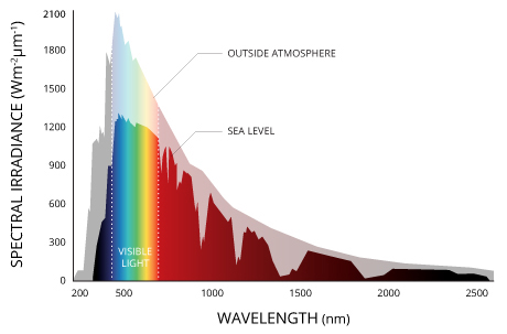
I'm wondering now if the 1350 watts of solation that Wikipedia reports per square meter on Earth might be limited to the visible spectrum.
I found a graph showing the spectral distribution of solar energy reaching Earth, and the bulk is in the Visible range. However, longer wavelengths are present in significant amounts.
(th)
Offline
Like button can go here
#227 2025-03-20 06:26:15
- tahanson43206
- Moderator
- Registered: 2018-04-27
- Posts: 24,936
Re: kbd512 Postings
For kbd512...
Glad you're feeling better!
Thanks for taking a look at the Optical Plane topic.
It is possible you haven't noticed that I did not hear back from Edmund Optical. I'm disappointed but not surprised.
The optical TIR device may not be available off the shelf, although lens of the required dimensions definitely are.
Edmund Optical is probably a distributor and not a manufacturer.
***
The next stage of development appears to be design of a test rig for the heating system. GW has drawn from earlier work and extended it to apply to the present concept, and I hope to have his latest work posted today.
Here's something for you to think about ....
A test rig could use hydrogen as the test gas, but hydrogen is dangerous. Nitrogen might work as well for the purpose of testing materials for the hot core. Are you aware of any reason nitrogen would not be acceptable as a substitute for hydrogen?
***
I've lost track of the performance data you provided...
We have a system size of 40 MW as a firm specification.
I'm a bit less sure of the material flow rate. I ** think ** that is 2 kilograms per second of LH2.
The desired ISP is 800 (matching NERVA?)
The associated temperature is 3000 Kelvin?
The possible thrust is 1/2 force-ton.
That 1/2 force ton is available as long as the LH2 holds out.
GW suggested carrying propellant in the keel under the optical deck.
Such a keel would provide the strength needed by the system to perform push operations, as appropriate for a space tug.
It ** should ** be possible to use the ordinary rocket equation to determine system performance, since we have ISP and propellant flow rate.
Half a ton-force is not much, but it could amount to something if it runs long enough. The mass of propellant is a variable that can be adjusted. I'm wondering what a graph of performance would look like if we plotted the variables in play.
Variables in play include the mass of the propellant, and thus the duration of thrust, as well as the mass of the vehicle and the customer vehicle.
(th)
Offline
Like button can go here
#228 2025-03-20 09:43:30
- kbd512
- Administrator
- Registered: 2015-01-02
- Posts: 8,533
Re: kbd512 Postings
tahanson43206,
Yes, testing can be performed with N2 vs H2. This is fairly common. The safety equipment required for using H2 as the test propellant dictates some fairly extreme equipment costs. Only a well-equipped university labs or NASA ion engine test facilities would have that kind of equipment. Performance values can be extrapolated.
H2 mass flow rate (mdot) was anticipated to be around 1kg/s. I think I originally empirically derived H2 flow rates obtained from NERVA documentation.
Target / desired Isp was 1,000s, which is how the 40MWth input figure was derived.
I believe 3,200K corresponds with a 1,000s Isp using H2 as the propellant, NOT the 2,750K I originally used.
Target thrust level was 10 kiloNewtons vs the 1kN I kept referencing. My memory is not what it used to be. Apologies.
Thrust = g0 * Isp * mdot
9,806.65N = 9.80665 * 1,000s * 1kg/s
mdot = Thrust / (Isp * g0)
1kg/s = 9,806.65N / (1,000s * 9.80665)
Isp = Ve / g0
1,000s = 9,806.65m/s / 9.80665
That all seems to check out.
We'll use 14,300J/kgK as the Specific Heat Capacity of Hydrogen gas, but the real input energy is here:
NIST - Hydrogen Specific Heat Capacity
14,300J * 3,200K = 45,760,000J/s of input thermal energy
1 Watt = 1 Joule per second
45,760,000J/s = 45,760,000W/hr
45.76MW <- Closer to actual input energy requirement
I think I remember what I initially did wrong. I miscalculated the temperature required. I think I used 2,750K or something like that.
14,300J * 2,750K = 39,325,000J/s <-- That was indeed my mistake
So...
45.76MW / 0.95 CoP = 48.168MW <-- This is closer to our true input optical power requirement, after accounting for 5% losses in the optical array. There will be some additional power losses involved with heating of the core. We need GW to tell us what those might be.
Offline
Like button can go here
#229 2025-03-20 10:05:09
- tahanson43206
- Moderator
- Registered: 2018-04-27
- Posts: 24,936
Re: kbd512 Postings
For kbd512 re Post #228
Thanks for adding details and clarifying as needed.
May I offer a suggestion? Please consider working with the system as it has evolved. 240 meters on a side is a very large array. It appears that temperature is a significant variable here, but GW has concerns about how the temperature will be achieved if we try to pass photons through quartz. He has proposed using hydrogen to cool the quartz facing the hot core.
You provided a number to work with of 40 MW, and the system as it stands reflects that value.
If we can confirm all the numbers for that size system, we can increase whichever parameters make sense.
I am hoping to find a supplier for the photon capture devices (TIR lens). The current proposed diameter is 36 mm with a 2mm border to allow for expansion when installed in a frame. That size leads to the 240 meter dimensions of the array.
***
Thanks for clarifying that Nitrogen is an acceptable substitute for Hydrogen for the test cell.
A number of materials are on offer for the heating fins.
The number of photon ports is to be determined, with a starting number of two.
There may be tradeoffs as the numbers of ports and fins are increased.
A value that would be of interest is the pressure that is going to be recorded inside the heating chamber. That pressure is going to be felt throughout the entire 240 meter length of the heat pipe.
The quartz windows must be able to withstand that pressure.
Cooling will be critical in this application. Failure of cooling at any of the quartz windows would lead to failure at that point, with possible loss of hot gas under extreme pressure. The frame is proposed to be made of carbon, so 3000 Kelvin gas would do some damage.
Perhaps the quartz windows could be designed to fail safe, by blocking the arriving photons at that location, but otherwise holding pressure.
(th)
Offline
Like button can go here
#230 2025-03-20 11:55:50
- kbd512
- Administrator
- Registered: 2015-01-02
- Posts: 8,533
Re: kbd512 Postings
tahanson43206,
The optical / thermal power input must increase slightly to achieve thrust closer to 10kN (for a 1kg/s propellant flow rate). I used the wrong temperature for achieving 1,000s Isp, but that was my target Isp for the design, because it reflected the maximum temperature that the engineers who worked on Project Timberwind believed was attainable using then-known ceramics.
I agree with GW about using the H2 propellant as regenerative engine coolant.
I don't think a 240m long quartz window heat pipe is very practical, so maybe I'm missing something, but you need purpose-built photon collectors and then you need a purpose-built rocket engine to dump the thermal power into the propellant to generate thrust.
Offline
Like button can go here
#231 2025-03-20 12:46:05
- tahanson43206
- Moderator
- Registered: 2018-04-27
- Posts: 24,936
Re: kbd512 Postings
For kdb512 re #230
This is a very interesting technical challenge, in any case.
I agree that GW's concept for a 240 meter long quartz tube looks difficult to fabricate as one piece, but perhaps there is a way to build this heat transfer system in smaller chunks.
I'd like to see what we can achieve with the 40 MW design. It turns out adjusting the power collected just amounts to arithmetic. The project needs stability, or nothing will ever be achieved.
As you predicted long ago, the optical part of this system is a (relatively speaking) easier part of the system than the heat exchanger.
If you are able to spare a bit of time looking, it would be helpful to learn if anyone has attempted anything like this in the past.
GW found documentation for a hypothetical solar balloon system, but (apparently) that was never developed beyond the conceptual stage.
***
Regarding the rocket engine length ....
That is up for adjustment. I proposed that as a logical consequence of the layout of the photon collection system. The shortest runs for fiber are horizontal along the ribs to the spine where the heat pipe could be located.
By distributing the heating over the entire 240 meters, the heat input at any one point is the same as everywhere else, so the components can be the same at every location in the structure.
(th)
Offline
Like button can go here
#232 2025-03-24 13:07:12
- tahanson43206
- Moderator
- Registered: 2018-04-27
- Posts: 24,936
Re: kbd512 Postings
For anyone searching for the post in which kbd512 shows an example of a chamber designed to heat gas passing through the device...
https://newmars.com/forums/viewtopic.php?id=10959
This is Post #9 of topic: Focused Solar Power Propulsion
Asymmetric turbulent flow resistojet test article:
(th)
Offline
Like button can go here
#233 2025-03-27 17:21:49
- tahanson43206
- Moderator
- Registered: 2018-04-27
- Posts: 24,936
Re: kbd512 Postings
For kbd512 re reactor images in post in Focused Solar topic...
The images you posted looked familiar...
https://newmars.com/forums/viewtopic.ph … 31#p229731
I had reported on a Canadian company that has been developing mechanically induced fusion.
The reactor you showed us looks a lot like one of their machines.
The idea they are pursuing is to use mechanical pumping to bring plasma to a density sufficient to support fusion for a brief interview.
Update: and here's a link to the web site for the company, with a nice animation showing how their system is supposed to work.
(th)
Offline
Like button can go here
#234 2025-03-29 06:11:19
- tahanson43206
- Moderator
- Registered: 2018-04-27
- Posts: 24,936
Re: kbd512 Postings
For kdb512 re https://newmars.com/forums/viewtopic.ph … 53#p230653
in Focused Solar.
Congratulations for finding this important citation!
And! Congratulations for finding much needed support for the validity of your idea!
As a small note for further study .... the idea of adding small thrusters is a good one, but they cannot (and will not) substitute for directing the force of the main engine through the center of gravity of the vessel.
(th)
Offline
Like button can go here
#235 2025-04-02 18:49:30
- tahanson43206
- Moderator
- Registered: 2018-04-27
- Posts: 24,936
Re: kbd512 Postings
For kbd512 re estimates for Optical Plane Space Tug...
I asked ChatGPT4o to try to compute the parameters for the engine based upon the three items you specified.
GW Johnson provided some advice as we went along. I have no way of knowing how well ChatGPT4o did, so am hoping you and GW will examine the work carefully and point out any errors that might have crept in.
https://newmars.com/forums/viewtopic.ph … 83#p230783
The post ahead of that one shows reasoning ahead of the calculations.
GW was looking for a throat area and ChatGPT4o came up with 58 square centimeters.
The pressure inside the hot bulb had to be estimated at 10 bar.
I'm hoping the heating chamber you are thinking about can handle that pressure.
(th)
Offline
Like button can go here
#236 2025-04-02 23:06:17
- kbd512
- Administrator
- Registered: 2015-01-02
- Posts: 8,533
Re: kbd512 Postings
tahanson43206,
The basic calculations used look correct to me, but real gas effects at the extreme temperatures involved are going to measurably affect the rocket's performance, so I'm curious about what our refined performance figures will be.
The actual specific heat of Hydrogen, for example, is going to affect the energy input requirement:
https://www.researchgate.net/profile/An … rature.png
Edit:
NASA Polynomial representation of molecular specific heats
This paper might be easier to read and access for you:
NASA Polynomial representation of molecular specific heats
Scroll down to the section entitled "Gas Phase Heat Capacity (Shomate Equation)":
NIST Chemistry WebBook - Hydrogen
Last edited by kbd512 (2025-04-02 23:15:31)
Offline
Like button can go here
#237 2025-04-04 08:46:49
- tahanson43206
- Moderator
- Registered: 2018-04-27
- Posts: 24,936
Re: kbd512 Postings
For kbd512 ...
First, thanks for #236
The references you provided look promising!
In this post, I'm contacting you ahead of Sunday's meeting, so you will be aware of something I learned while working with Gemini to try to understand the design issues for the heat engine for the Solar Propulsion system for the Optical Plane Space Tug.
I'd like to toss into the ring a suggestion that we first saw from GW, but is now reinforced by Gemini.
We have 240 meters to work with to heat our propellant.
I have suggested a minimum length for the engine of five meters, based only on the physical area needed to deliver 40,000,000 optical feeds.
We have an opportunity to consider more than one option, as we attempt to design a system that has never been seen before.
The idea that came to me as a result of Gemini's prompting is a two stage heating system.
Quartz can only hold together up to a certain temperature, far below where you want to go. However, the design that GW offered has the distinct advantage of allowing radiation to enter the heating chamber where it heats the central black component while also heating gas molecules directly with UV (the UV is much less of a factor than other wavelengths, but why not use it if it is available?).
The feed from the quartz section can then feed into the solid wall section where the goal is to try to achieve 3000 Kelvin.
An issue that arose during my session with Gemini is whether 40 MW is sufficient to provide the heating you've asked for.
You did some calculations early on, and I'm hoping you can bring those back.
The time the hydrogen spends in the heating system turns out to be a significant factor, which up to now we have not been considering.
(th)
Offline
Like button can go here
#238 2025-04-05 14:35:51
- tahanson43206
- Moderator
- Registered: 2018-04-27
- Posts: 24,936
Re: kbd512 Postings
For kbd512 re post https://newmars.com/forums/viewtopic.ph … 88#p230888 in Focused...
Thank you for taking a look at the attempt by ChatGPT4o to "think" about the problem of heating hydrogen from 300 Kelvin to 3000 Kelvin in a finite distance.
I agree that the figure it came up with seems large, but it occurred to me afterward that there is NO reason a particular hydrogen molecule has to transit the facility in one second. It is the throughput that has to add up to an average of 1 second per 2 kilograms of material.
It ** did ** offer a suggestion that travel through the NERVA system might not be a straight line. Your suggestion of a convoluted pathway seems possible, in the absence of any details about NERVA. I'm hoping some details come our way, but right now I'm not aware of any. There are suggestions for places to look in the ChatGPT4o and Gemini transcripts, but I've not had time to look.
One thing that seems clear at this point. It takes a certain amount of time to heat a kilogram of hydrogen from 300 K to 3000 K given a fixed amount of energy input. ChatGPT4o seems to "think" 40 Mw is not sufficient, so that is a place I hope someone will look.
FYI ... GW has been working on nozzle and expansion bell design. At this point the heating subsystem remains "to be defined", except that we have two options and they are NOT exclusive. We have GW's suggestion of quartz windows and a central hot core, and we have your suggestion of a hot exterior and convoluted interior. I say they are not exclusive because one can feed into the other.
(th)
Offline
Like button can go here
#239 2025-04-05 14:44:10
- kbd512
- Administrator
- Registered: 2015-01-02
- Posts: 8,533
Re: kbd512 Postings
tahanson43206,
Could the disconnect be the surface area over which the 2kg of Hydrogen is in contact with?
That seems like the most probable explanation.
Offline
Like button can go here
#240 2025-04-05 14:49:07
- tahanson43206
- Moderator
- Registered: 2018-04-27
- Posts: 24,936
Re: kbd512 Postings
For kbd512 re #239
Thanks for a ** very ** helpful insight!
I'll follow up as soon as a convenient time arrives.
FYI .... GW is going to be busy for the next couple or few days, so we may not hear from him. His most recent contribution is a set of images and calculations that I put in the GW Johnson topic. The one that you might find particularly interesting (I hope) is the last addition, in which did some preliminary work on nozzles.
Update: ChatGPT4o seems to think we need all 240 meters for the engine heat transfer function.
I know you are interested in a small volume for the engine, but let's stay with this for the moment because it provides a parameter GW needs for nozzle design.
(th)
Offline
Like button can go here
#241 2025-04-06 09:46:53
- tahanson43206
- Moderator
- Registered: 2018-04-27
- Posts: 24,936
Re: kbd512 Postings
For kbd512 re #240
Thanks again for that very helpful suggestion! I followed up and ChatGPT4o "thinks" we can achieve 22 bar at 2500 Kelvin.
Meanwhile, GW ran numbers at two lesser pressures:
Solar Rocket Nozzle Results
GWJ
4-5-2025
I ran this study simply presuming that a fixed flow rate of 2 kg/s of 3000 K hydrogen was
made available at the nozzle entrance. All I did was vary expansion area ratio Ae/At from 50
to 300 in steps of 50, at a fixed Pc = 100 psia (6.895 bar), and a second time at Pc = 50 psia(3.447 bar), out in vacuum
In case GW cannot attend this evening, we have an opportunity to try his spreadsheet using the 22 bar and 2500 K assumptions.
GW wrote by email that he found that (theoretically) hydrogen could deliver 2 force-tons at 3000 K.
Obviously we are not going to achieve that because of losses at every point in the system, but it is nice to know the theoretical thrust is so high.
***
Steering the vessel at the nozzle may not be possible. We can compensate by making the docking mechanism a pivot point, so thrust can go through CG of the client vessel.
(th)
Offline
Like button can go here
#242 2025-04-06 21:09:35
- tahanson43206
- Moderator
- Registered: 2018-04-27
- Posts: 24,936
Re: kbd512 Postings
For kbd512 re post in Google Meeting: https://newmars.com/forums/viewtopic.ph … 30#p230930
Awesome!
I wish we had more members who could appreciate your discoveries.
Perhaps we'll win more members by staying with the effort.
(th)
Offline
Like button can go here
#243 2025-04-07 17:27:28
- tahanson43206
- Moderator
- Registered: 2018-04-27
- Posts: 24,936
Re: kbd512 Postings
For kbd512 re update on NERVA heating design https://newmars.com/forums/viewtopic.ph … 44#p230944
I've updated the index. I'd be willing to update the index further.
Question: do you have any data on conditions inside the reactor at run time?
1) What was the flow rate of hydrogen?
2) What power was generated? (We are going with 40 MW because that was an amount you chose to start us out)
3) Is there any record of dwell time of hydrogen inside the reactor
I noted your mention of the interesting interval between leaving the hot reactor and passing through the exit plane.
The source from which you drew that apparently thought cooling took place then, but it is hard for me to see how there could have been much cooling because the gas would have been moving at sonic speed at that point, but apparently there was enough so whoever you were quoting commented upon it.
Niece piece!
(th)
Offline
Like button can go here
#244 2025-04-08 03:24:37
- kbd512
- Administrator
- Registered: 2015-01-02
- Posts: 8,533
Re: kbd512 Postings
tahanson43206,
1. Flow rate is dependent upon temperature, pressure, and thermal power input into the propellant (a 1,000MWth engine is going to flow more propellant than a 100MWth engine, so if temp / pressure / throat area / expansion ratio are all proportional, we would expect 10X greater propellant flow rate).
2. Engine data for a real engine (XE Prime) and proposed engine for flight testing (Alpha) appears below:
NERVA XE Prime
Core power output: 1,137MWth
Weight (complete engine): 18,144kg
Thrust (vac): 246,663N
Isp (vac): 841s
Hydrogen flow rate: 32.7kg/s (full output)
Core temp 2,270K (full output)
Chamber pressure: 593.1psi
NERVA Alpha (first flight-ready engine design, never built)
Core power output: 367MWth
Weight (complete engine): 2,550kg
Thrust (vac): 72,975N
Isp (vac): 875s
Hydrogen flow rate: 15kg/s (full output); 95.5kg/s (startup); 15kg/s (shutdown)
Core temp 2,880K (full output); 60K temp reduction to provide 2 full hours of operation without excessive fuel loss from erosion
Chamber pressure: not provided
Thermal stress limit: 83K/s (max heating rate ramp-up to prevent thermal over-stress of the Graphite fuel rods)
This document contains Hydrogen mass flow rate, heat transfer surface area, inlet velocity, outlet velocity, and fuel assembly length data:
Idaho National Laboratory - Scoping Analysis of Nuclear Rocket Reactor Cores Using Ceramic Fuel Plates - January 2020
H2 inlet velocity is 100m/s (at 400K), outlet velocity is 800m/s (at 2,800K), the fuel assembly length is 80cm, as found on Page 49.
Check out how radically Hydrogen's thermal conductivity increases between 400K and 3,000K on Page 50 of the above document.
I bet that AI program isn't accounting for Hydrogen thermal conductivity increase as temperature increases, pressure, and surface area of the propellant channel. In any event, this detail level data only reinforces the idea that what I proposed doing with the engine geometry will work, and whatever that AI program is telling us about needing a 1.4km long flow channel to provide the necessary residence time is an error based upon some very simplistic assumptions about geometry and flow that don't come close to approximating a real engine design.
Offline
Like button can go here
#245 2025-04-08 07:41:51
- tahanson43206
- Moderator
- Registered: 2018-04-27
- Posts: 24,936
Re: kbd512 Postings
For kbd512 re #244
Thank you for doing the research to find those numbers!
I've stored a few calculations here: https://newmars.com/forums/viewtopic.ph … 49#p230949
I made an error that led to the 240 meters on a side estimate for the 40 MW optical collector.
There are 10 square centimeters in 1000th of a square meter, not 1 as I had assumed earlier.
The chamber pressure of the NERVA XE Prime is given as 593.1 psi which equates to 40.892 bar.
Your heating chamber needs to be able to hold whatever bar level we decide upon.
Please note that pressure is a factor in thermal conductivity, but I'm not sure of how it relates.
The flow rate of NERVA XE Prime was higher than the level of 1 kg/s we seem to be headed toward.
GW seems to think he can deliver just under one metric force-ton if you can deliver 1 kg/s at 3000 Kelvin.
Something you do not seem to be taking into account is the length of the fiber optic lines. I computed the total length of all feeds if we used your concept of a small engine at the bottom, and the total is an astonishing number.
The smallest possible length of fiber is achieved by running the feeds directly across the wings to the spin and delivering Photons at the spine.
However, it may turn out that the Photons must be delivered in greater numbers to achieve high temperature at a given location, and that would be an argument in favor of a shorter engine length.
Research you could do that would be helpful is to find how the maximum internal pressure a carbon structure can hold if it is glowing hot.
The higher the pressure developed the better (apparently).
GW's computations were done for 6 bar and 3.5 bar. I think it makes sense to start there, because that gives you the nearly one force-ton thrust that would be an impressive achievement for only 40 MW.
(th)
Offline
Like button can go here
#246 2025-04-08 07:55:44
- tahanson43206
- Moderator
- Registered: 2018-04-27
- Posts: 24,936
Re: kbd512 Postings
For kbd512 re NERVA documentation ...
A detail I did not see in the collection you provided was the dwell time of hydrogen in the heating tubes.
We can see that the tubes are abundant, and we have the word "small" for the throat.
We know the flow rate thanks to your research.
If we had the throat area and the area of the tubes, then we could compute the dwell time.
The flow rate you found is NOT the same thing as the flow rate through the heating tubes.
The flow rate you found is the flow rate through the throat.
We can deduce that the area of the heating tubes is greater than the area of the throat, but all we can do is to guess what that means.
As an example of a guess, if the area of the tubes is twice that of the throat, then the average flow through the tubes is half that of the flow through the throat.
Thermal conductivity appears to be dependent upon time spent in proximity to hot surfaces, as well as the temperature of those surfaces and the pressure.
(th)
Offline
Like button can go here
#247 2025-04-08 14:39:03
- kbd512
- Administrator
- Registered: 2015-01-02
- Posts: 8,533
Re: kbd512 Postings
tahanson43206,
Flow velocity, from core entrance to core exit, and thus residence / "dwell" time, can be computed by using the acceleration across the 80cm fuel pin length containing the hollow "tubes" for the Hydrogen propellant to flow through.
a = (Vf^2 - Vi^2) / (2 * d)
a = (800m/s^2 - 100m/s^2) / (2 * 0.8)
a = (640,000 - 10,000) / 1.6
a = 630,000 / 1.6
a = 393,750m/s
The "dwell time" is thus 0.8m / 393,750m/s, so 0.000002031746032 seconds. That's how fast the Hydrogen gas moves from core entrance to core exit, based upon the acceleration rate through the 80cm / 0.8m long heat transfer "tubes" drilled through the Graphite fuel pins in the core of that nuclear thermal rocket engine.
If we have a 10m long channel wall nozzle for external solar heating to be applied to, then we have:
a = (800m/s^2 - 100m/s^2) / (2 * 10)
a = 630,000 / 20
a = 31,500m/s
That means "dwell time" is thus 10 / 31,500m/s, so 0.00031746031746 seconds. That's dramatically more dwell time.
The actual spiral flow path I envisioned would be at least 100m in length, possibly 300m or more, so 0.0031746031746 seconds.
That means our solar thermal rocket's propellant stream would easily have sufficient time and distance to get the propellant up to temperature, plus a lot more residence / dwell time than a prototypical nuclear thermal rocket engine's fuel pin length.
If the propellant channel is only a few millimeters in diameter and that flow channel winds around the circumference of our large Graphite nozzle, the actual flow path could be very long, which means we have very uniform heating, improved Isp, greatly reduced thermal-hydraulic stress, and an all-around easier design proposition because the Graphite is homogeneous, meaning not loaded with any highly reactive Uranium particles, not subject to rapid fission product release.
Graphite room temperature tensile strength ranges from 8MPa (1,160.3psi) to 30MPa (4,351.13psi), and is highly dependent upon how fine the grain size of the Graphite happens to be. Unlike metals which get weaker at high temperatures, Graphite gets stronger up to a temperature of about 3,200K or so, so at 2,800K I think its tensile strength (ability to resist being pulled apart) and flexural strength (ability to resist bending) properties are about 1.5X greater than at room temperature. NERVA operated at pressures up to 550psi, although about half that at stabilized full power output. Startup and shutdown is what induces a lot of thermal-hydraulic stress. Graphite at room temperature can resist NERVA operating pressures adequately. A very fine grain sintered / molded structure, which will have properties closer to 30MPa, will easily resist the pressurization of the Hydrogen.
Do you recall how I said operating at very low pressures and very high temperatures confers a substantial Isp advantage (reduced propellant mass flow for a given thrust)?
That is what we're going to do with this engine design. We want reduced pressures and higher temperatures. Higher operating pressure leads to smaller nuclear reactor cores, thus reduced reactor weight required to provide that internal heating, at the expense of Isp. At this thrust level, we apparently do not need a "core" at all. We can do all of our heating inside of a large nozzle, which provides a large surface area for even distribution of that 40MWth (1,000kgf) or 77MWth (2,000kgf).
If we further concentrate that Sunlight beyond what was actually used in the 1970s Rockwell experiments using mylar parabolic dish mirrors, then we can increase temperature beyond all known material limits, if we so choose. Rockwell had no trouble at all concentrating the sunlight to a "spot size" that would cause Graphite to sublime. It was more a case of "don't concentrate the sunlight so much that you vaporize your rocket engine". Therefore, the tolerable sunlight concentration limit sets the upper bound on Isp and the lower bound on the surface area of the rocket engine nozzle to spread the heat over. We can easily go hot enough to vaporize Tungsten, but we cease to have a rocket engine at that point.
The solar thermal rocket engine design imperatives are as follows:
1. Build the channel wall nozzle with enough surface area so as not to sublime the Graphite into space when struck by the giant solar death ray, which implies increasing the nozzle's expansion ratio for the express purpose of providing more surface area for the heat to be applied to, until weight starts to become a factor. Graphite is pretty light stuff, relative to virtually all structural metals, and as strong as it needs to be. The Isp benefit from a greater expansion ratio is the "gravy" you get for doing this. Nozzle kinetic efficiency with Hydrogen propellant will bound this as well. Only certain geometries and lengths, for given chamber pressures, are permissible.
2. Operate at as low a pressure and as high a temperature as material thermal limits and reasonable nozzle weight will allow for, because this can dramatically increase Isp, in the range of 40s (5bar at 3,000K) to 200s (5bar at 4,000K). This is due to the percentage of atomic vs molecular Hydrogen generated by the extreme heat causing thermal dissociation of the propellant. If you operate at 60bar, then you only do that to decrease the core volume / length of a nuclear reactor, knowing full well that you're "losing heat", but greatly reducing core mass and size at the same time, because enriched Uranium and Beryllium are very expensive and shielding is very heavy.
They actually performed a study on this and concluded that low pressure / high temperature was "most optimal". The paper is on OSTI's website (scroll down to Page #8, which is actually 9 of 13 in the PDF file, and the next few pages, to see what I'm talking about):
ULTRA-HIGH TEMPERATURE DIRECT PROPULSION
3. We're going to optimize the internal channel geometry and shaping to induce turbulent flow for the express purpose of picking up more heat more efficiently. That resistojet rocket's internal propellant flow channel geometry with the external resistive heating elements did the same thing, in order to economize on heat transfer efficiency, by increasing the propellant's "dwell time", which resulted in higher Isp. Our reasoning for adopting their internal geometry is more about uniform heating and reduction of thermal hydraulic stress than it is about "getting more juice per squeeze". We already have more than enough flow path, as evidenced by the very short length of the fuel pins in the nuclear thermal rockets. What all NTR designs did, which that OSU paper pointed out and sought to correct for, was a relatively poor job of uniform heating, which both reduced effective Isp (sometimes by quite a bit) and made their Graphite fuel assemblies weaker and more subject to cracking failure from induced thermal-hydraulic stresses caused by huge temperature gradients.
Offline
Like button can go here
#248 2025-04-08 15:53:32
- kbd512
- Administrator
- Registered: 2015-01-02
- Posts: 8,533
Re: kbd512 Postings
More succinctly:
1. We can afford to have a larger expansion nozzle that pulls double duty as our heat input surface area for the sunlight to shine on. We don't have any reactor core mass, length, or radioactivity complications (control rods, fuel and moderator rods, coolant channels to cool the Inconel pressure vessel and Beryllium reflector) to account for. This allows us to achieve higher temperatures within our pure Graphite "engine". The overall weight is less than a reactor. The length of the nozzle could be as long as a complete nuclear thermal engine happens to be for equal power output, and it would make no difference to how difficult it was to transport or deploy the device.
Since we opted for pure Graphite construction, we don't need regenerative cooling. A solar thermal engine doesn't have a reactor pressure vessel, throat, and chamber made from Inconel, nor a giant reflector made from Beryllium, which must be kept cool since those metals all melt at much lower temperatures than Graphite. Inside a nuclear thermal rocket engine the Hydrogen propellant is most definitely confined within the propellant flow passages drilled through the Graphite fuel rods, so that base material absolutely is strong enough to withstand the pressures, because it has to be, else said Hydrogen gas expansion through the propellant flow passages ruptures those Graphite fuel rods and destroys the nuclear rocket engine. We will be applying less pressure, less stress, and to a homogeneous Graphite material, at virtually the same temperatures reached by the hottest parts of the nuclear thermal rocket engine core. The real difference is that our heat application won't be nearly as non-uniform as it is inside a nuclear thermal engine.
2. We benefit from using a very circuitous internal Hydrogen flow path for the propellant to make contact with, to uniformly absorb the externally applied heating from the Sun. Again, this means we don't have temperature gradients quite as high as a nuclear thermal engine. Some of the peripheral fuel pins in the nuclear thermal engine could be 500K+ cooler than the fuel pins in the center of the core, with the end result that much hotter and cooler gas mixes together ahead of the engine's throat after it exits the fueled portion of the reactor core, which is where that "significant heat loss" comes from, which I spoke of.
3. We can achieve a higher expansion ratio, which further improves Isp, because we have this monolithic "hollow" Graphite channel wall nozzle / engine structure. The length of said nozzle is somewhat less critical when there is no nuclear reactor core positioned ahead of the nozzle. NERVA XE Prime was 6.9m in length and was to use a mechanically extendable uncooled nozzle extension made from Carbon. Since our engine uses external surface heating only, we can transform our engine into a "giant nozzle" 6.9m long, and we've given up nothing to the original NERVA design in terms of overall engine length.
4. Our solution will be heavier because it uses fiber optics and/or mirrors to collect photons from the Sun, but in terms of cost and the difficulty of working with the materials, nothing we're doing or working with are government-controlled / furnished materials or classified. Maybe the Hafnium Carbide is a government-restricted aerospace material, but if so we can fall back on Zirconium Carbide. Mylar, Graphite, fiber optics, and such do not even qualify as restricted items. There will be some trade secrets and Uncle Sam will declare that the engine is ITAR-restricted if it receives any government funding, but that's about it. The composite Hydrogen propellant tanks qualify as ITAR-restricted rocketry tech.
5. In terms of cost, I've little doubt that a solar thermal engine will be far less costly than a nuclear thermal engine, thus more attainable if we pursue this technology. We assert that the primary reason for continued development of nuclear thermal engines is the Isp benefit that nuclear thermal can achieve. We can achieve the same or slightly superior Isp using direct solar heating, and there will be fewer objections to the launch. There's nothing truly remarkable about the materials or fuels being used here. It's all very standard stuff that is mass-produced here in America and elsewhere. Foreign allied customers can benefit from the ability to place very heavy satellites in high orbits and send less mass-constrained space probes wherever they so choose, because the mass and cost associated with doing so is half that of the best LOX/LH2 engines. Heavier propellants such as Methane or Ammonia or CO2, which are easier to store and generate more thrust, can be used to achieve Isp figures similar to more complex LOX/LCH4 or LOX/LH2 bi-propellant chemical rocket engines. The solar collector size and thrust generated can be tailored to desired specifications. We're starting with either a 1,000kgf or 2,000kgf engine because that is sufficient to send a truly massive interplanetary transport vehicle on its way, in about a month.
Offline
Like button can go here
#249 2025-04-09 06:07:36
- tahanson43206
- Moderator
- Registered: 2018-04-27
- Posts: 24,936
Re: kbd512 Postings
For kbd512 re Solar Propulsion initiative...
It appears we can use carbon to absorb Photons, and we can use a suitable metal interior lining to protect the carbon from erosion.
Please proceed to develop your concept for a short Hot Bulb. I will be very interested in your progress. You will want to find a way to organize 40,000,000 fibers to shine on your Hot Bulb simultaneously. The diameter of each fiber is given as 9 (nine) microns. You can employ whatever strategy seems to make sense. I have not been able to discover the diameter of the cable with protective covering. The cable will be exposed to vacuum, so an outer coating would appear to be advisable.
I will simultaneously be looking at the long run version of the Hot Bulb.
Let's try to have the results ready for the next Google Meeting.
For reference per Google:
Multimode fiber is available in two sizes, 50 micron and 62.5 micron. Singlemode fiber is typically used in network connections over long lengths and is available in a core diameter of 9 microns (8.3 microns to be exact). Both 50 micron and 62.5 micron fiber optic cables use an LED or laser light source
A concern I have is how well communications grade fiber transmits the full spectrum of sunlight.
Update: Revised and corrected data for the light collecting surface is here:
https://newmars.com/forums/viewtopic.ph … 49#p230949
(th)
Offline
Like button can go here
#250 2025-04-09 13:08:28
- kbd512
- Administrator
- Registered: 2015-01-02
- Posts: 8,533
Re: kbd512 Postings
tahanson43206,
If you find a refractory metal alloy that matches the coefficient of thermal expansion of Graphite by the time it reaches 3,000K, please let me know, because that would be very interesting to me. Until then, I'm going to presume that we're not using metal since the only metals I'm aware of with melting points at or above the target temperature are Niobium, Molybdenum, Tantalum, Rhenium, and Tungsten. None of those metals have CTEs close to Graphite and none of them transfer heat as well as Graphite.
Edit:
Since you're fixated on using metal, how about a 90% Tungsten 10% Copper alloy, which will still melt near 3,400C / 3,673K?
That alloy is at least weldable and formable without too much difficulty, and is noted for good thermal fatigue properties. The materials cost alone will be around half million dollars for 1,200kg of material or so ($400/kg).
Take a look at how far the yield strength figures drop by the time you reach the temperature range we're operating at:
Yield strength of Tungsten and some of its high strength alloys
25ksi is all you're going to get at 3,000K, as the chart above shows. It's better than the 6.5ksi of fine grain synthetic Graphite, but I have no idea what the creep characteristics of that alloy will be, nor how it will perform with hot flowing Hydrogen. We can use the same aerospace coatings to try to slow the rate of embrittlement, but that's about it.
Edit #2:
In case you're wondering, I chose W-Cu alloy based upon its low CTE and higher than average resistance to Hydrogen embrittlement, but I don't have data for 3,000K. As with all other metals, it's almost silly putty at 3,000K, relative to room temperature, but the only other alloys capable of surviving at the temperatures in question are even more expensive than W-Cu alloy and there's not much data about their Hydrogen embrittlement resistance in the temperature range we're interested in. I think Niobium alloys are the only other type that might be suitable, but I don't know much about them because they're very exotic stuff. Maybe NASA has some data on them. Niobium alloys have been used in uncooled rocket engine nozzles during the Apollo Program. The LEM's main engine, for example, was made from a Niobium alloy of some kind.
Last edited by kbd512 (2025-04-09 13:46:32)
Offline
Like button can go here