You are not logged in.
- Topics: Active | Unanswered
Announcement
#51 Re: Home improvements » Misc. Home Projects » 2025-12-04 03:39:01
I would probably build a much simpler vertical axis machine were I to do it again. Efficiency is lower, but the ease of construction and assembly make it more practical overall. Above all else, the design needs to minimise the need for working at height. If there is a rotor that needs maintenance or adjustment, then there needs to be a capability of lowering it down the pole for work, without having to work at height. Working at height means putting up scaffold and introduces problems of working in confined space, confined angle and having to avoid vibration. It slows things down dramatically.
One important thing I have learned is that the best solution is very dependant on local conditions. Midwest farms on flat land with a consistant wind direction, are well suited to the jumbo type ground mounted wind machines. Locations with variable wind directions are better suited to vertical axis designs that can make use of wind from any direction. Locations with a cluttered near surface environment need towers to overcome surface attenuation. If there is limited space, a horizontal axis machine offers greater efficiency. Local geography can sometimes be used to focus the wind. The availability of materials will have an impact as well.
#52 Re: Meta New Mars » Calliban Postings including links to notable contributions » 2025-12-04 03:04:00
I will get back on the the brick dome project today. Between work and other hobbies, I have been stretched for time these past few weeks.
#53 Re: Science, Technology, and Astronomy » Thermal Efficiency in Propulsion » 2025-12-04 02:58:40
The new CatGen catalyst bed technology promisses more compact and fuel efficient GT engines.
https://youtu.be/-TDoteS9QZA
I can see a number of problems with this idea in practice.
1. Whilst the catalyst allows efficient combustion in a compact volume, its presence limits combustion temperature to the melting point of the catalyst and substrate. This places limits on cycle efficiency.
2. The catalyst bed adds weight.
3. The compressor must force air through the narrow channels of the cataylst bed, which increases pumping losses through the engine. In a conventional GT, compression already consumes at least half of the energy produced by the turbine.
4. Although the video talks about the tolerance of the catalyst to different fuels, the reality is that fuels containing sulphur or soot will poison the catalyst.
In spite of these problems, this engine concept may offer value in burning lean fuel mixtures that would not otherwise support combustion. In the Martian context, we know that the Martian atmosphere contains small amounts of CO and O2. If CO2 can be seperated from the bulk air, the remaining gas mix could be preheated and passed through a catalyst bed to extract energy. Given the small concentration of CO, this is unlikely to be a net energy producing reaction. But assuming we are inputting energy to extract specific gases from the Martian atmosphere, this reaction would allow some portion of input energy to be recovered. It also scrubs CO out of the N2/Ar gas mix, which is important if we are gathering life support gases.
#54 Re: Home improvements » Misc. Home Projects » 2025-12-03 07:03:44
The rotor bearings are now in their cradle supports. There is still more to do before the windmill is operational. Whilst it has been a valuable learning exercise, I would certainly do things differently if I were to build another. This has been the toughest DIY project I have ever taken on. Everything is an order of magnitude more difficult when working at height.
#55 Re: Home improvements » Solar Installation in McGregor, Texas August 2024 Start » 2025-12-03 06:58:33
GW,
Out of interest, what would you estimates the rate of return on your investment to be?
#56 Re: Not So Free Chat » Chat » 2025-12-03 06:54:36
Another flight. This time to Kingfisher Lake z Ontario. Early morning flight on a Metrliner aircraft. Twin turbojet, one seat on each side of the isle. Narrow, no overhead bin, ceiling barely high enough for my head, seats on a platform, one step up. No under belly cargo hold. Cargo in back.
Hope you enjoy the trip. It sounds like an adventure.
#57 Re: Not So Free Chat » Politics » 2025-12-03 00:58:00
A man has been jailed in the UK for 'possessing rightwing music'.
https://youtu.be/kKrBDsFBlxw
#58 Re: Home improvements » Misc. Home Projects » 2025-12-02 10:04:19
I have lifted the rotor onto the tower. The bearings are not in the cradles yet, but it is tied to the frame.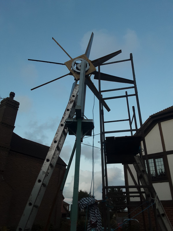
The rotor is heavier than last time and is proving to be an absolute pig to install. Trying to lift it is is hard enough. But lifting and manoevring the thing whilst standing on a 20' high platform makes it 10x harder. There is a lesson in there somewhere.
#59 Re: Meta New Mars » Calliban Postings including links to notable contributions » 2025-12-01 16:32:17
TH, impressive image.
#60 Re: Home improvements » Misc. Home Projects » 2025-12-01 16:30:35
GW, thanks for this. I am going to attempt static balancing on the ground before lifting the rotor up the tower. I don't know if static balancing will be sufficient, and I am not exactly skilled in performing it. But I cannot imagine tip speed being as great as a car tire at 70mph. I will report here how things progress.
#61 Re: Meta New Mars » kbd512 Postings » 2025-12-01 16:22:24
Kbd512, thanks for this. I am going to attempt to balance the rotor on the ground before lifting it up the tower. My rotor will work at a far lower rotational speed compared to an aircraft propeller. But vibration could damage the cradle supports, bearings and tower over time. So I want to balance the rotor as well as possible. The weather has been awful here today, but looks better tomorrow, so I should be able to make progress and report on results.
#62 Re: Exploration to Settlement Creation » Calliban's Brick Dome on Mars » 2025-12-01 08:48:15
A lot to catch up on here. If we can build the dome in a depression like a crater, then it simplifies building up the overburden. A classic hemisphere is not actually stable under compressive force. The apex experiences shearing forces and the base circumference experiences stretching forces that tend to bulge outwards. A hemisphere is not ideal for a masonry structure without reinforcement. A catenary (parabolic) dome is a more stable arrangement. I am not sure exactly what geometry would work best.
I do not see us attempting a masonry dome as an early base concept. Our first projects will be on a more modest scale. I think Nubian vaults will be easiest structures to build, because they do not require formwork. We could add penditives where they cross, allowing a grid type arrangement. This doesn't provide inhabitants with much in the way of wide open spaces. But in early settlements, we need structures that are quick and affordable to build.
#63 Re: Home improvements » Misc. Home Projects » 2025-12-01 08:29:39
Calliban,
Irrespective of how light or heavy the completed rotor assembly happens to be, it's going to work better when balanced.
Have you already done that already, or is it on your "to do" list?
It is on the to do list. I know the rotor is out of balance because one of the blades is slightly out of alignment from when I dropped the rotor whilst trying to install it. When it is mounted on its bearings, I will be able to trim it by adding steel strip to the blades. I doubt that I can fix the problem entirely.
The weather is poor at present. It is raining with a 40mph gale. The scaffold is up, but I wont be able to install the rotor before tomorrow at the soonest.
After work today, I am going to start work on a table saw. This will be a cubic wooden box with internal dimensions 12", sufficient for a 10" diameter circular saw blade. I can use this to saw firewood. The thing that is taking time is safety features. The saw will carry the female part of the cone clutch. The saw box will be mounted on rails and will be pushed against a spring until the two parts of the the clutch fit together. A peg is then inserted, holding the saw box in place against the compression spring. To seperate the two parts of the clutch, the peg can be pulled out, and the compression spring pushes the two parts of the clutch apart. It will take me at least a few days to build this. But it will be the first tool that I build for the machine. It is therefore a proof of concept.
#64 Re: Home improvements » Misc. Home Projects » 2025-11-30 07:51:48
Some additional pictures. The rotor is quite heavy now, in spite of my efforts to reduce the weight of the new blades.


#65 Re: Home improvements » Misc. Home Projects » 2025-11-30 05:22:29
I have added four new blades to the rotor of my machine and made some improvements to the pulley.
When the paint is dry, the rotor can be installed. I will be putting up the scaffold today.
#66 Re: Home improvements » Misc. Home Projects » 2025-11-23 03:44:33
I have started work on the windmill again. Yesterday, I built four new blades. Today I paint them.
I have saved quite a lot of cost and weight this time. The blades are made from pine wood, 3mm ultrathin plywood and aluminium from recycled drink cans. This is very thin ~0.1mm guage. As before, everything is glued together with epoxy resin. I will post pictures in due course.
#67 Re: Not So Free Chat » Chat » 2025-11-23 03:37:10
Why British people looked older than they were in old photos.
https://youtu.be/ECfhU_I9mjQ
In short, life was tougher. The air was polluted, food was unhealthy, almost everyone smoked. The work environment was dangerous and polluted.
#68 Re: Terraformation » Solar Reflections from Orbits to a Worlds Dark Spots, Mega Structures » 2025-11-17 13:48:19
One option that I have sometimes wondered about is to build the ship in a way that makes it easy to seperate things like the engines and control systems. We could pack these into a relatively compact module for reentry and recovery. The tankage and fuselage can then be cannibalised in orbit. Having paid to blast these things into orbit, it is questionable to then waste that invested energy by dumping it in Earth atmosphere.
Doing things in this way means making a lot more rocket vehicles. But this introduces economies of scale that can bring down costs in a different way. Definitely something that will have crossed Elon Musk's mind from time to time.
#69 Re: Home improvements » Misc. Home Projects » 2025-11-16 13:01:37
I will be resuming work on my windmill on Tuesday. I am hoping to have it finished and up and running a week today. Making tools will take a while longer.
#70 Re: Not So Free Chat » Politics » 2025-11-16 12:35:28
When someone fights for your country, they deserve your respect. If they choose to apply for citizenship, military service should be taken into account in reaching a decision. Should it provide an automatic pass? Absolutely not. When you make someone a citizen, you are permanently inviting them and their descendants into the extended family of your nation. That is not a decision to reach lightly. This man committed a serious felony. His military service and injuries should have been taken into account when deciding his sentence. Presumably, they were. But expecting to enter the American extended family having committed attempted murder on American soil would be unreasonable.
#71 Re: Exploration to Settlement Creation » Calliban's Brick Dome on Mars » 2025-11-16 11:45:55
The problem with building large and thin masonry domes, is not the strength of the materials, it is stability. Prior to pressurisation, the dome will be subject to external forces from the overburden. If these are too high, they will buckle the dome inwards, even if the crush strength of the dome is never exceeded. The critical external pressure that could result in buckling instability for a sphere or hemisphere, is given by:
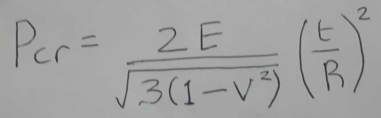
Where:
Pcr = critical external pressure for onset of buckling (Pa);
E = Young's Modulus (Pa);
v = Poisson's Ratio;
t = dome wall thickness (m);
R = Dome radius (100m).
For Class A engineering brick, Poisson's Ratio is 0.15 - 0.25. I have taken an average value of 0.2. I could not find a value of Young's Modulus for hard engineering bricks. This site proposes a value of 20GPa for brick generally.
https://www.engineering.com/youngs-modu … the-brick/
We will be putting enough overburden on the dome to impart a 50KPa external pressure. This will be sufficient to counteract internal pressure when the dome is fully pressurised. Prior to pressurisation, during construction, there will be a net inward pressure of 50KPa acting downwards. Maximum effective pressure will be experienced at the dome apex. This is where buckling is most likely to occur.
Solving for the known variables, gives a minimum stable value of t of 14.56cm. The mortar between bricks will also effect youngs modulus of the structure. We are planning to use epoxy resin to glue the bricks together. However, assuming that individual bricks are polished, only a very thin layer (0.1mm) of epoxy need be applied to bond them. So the effect of the mortar in this case will be minimal. With this in mind, for a 200m diameter dome, wall thickness should not be less than 14.56cm. A thickness of 20cm allows for some margin of safety.
Of course, the dome presented here is not a perfect hemisphere. It is parabolic, which allows downward compressive forces to be absorbed with reduced shearing stress within the structure. This reduces the risk of buckling. In addition, Martian regolith is known to possess adhesive properties due to its high iron oxide content. Indeed, compressing regolith fines in a mold would produce a reasonably strong ceramic. This gives reason to expect that any compacted regolith layer would tend to redistribute load around the dome, reducing the downward pressure acting on the apex. These factors tend to suggest that the calculated value of minimum safe thickness is conservative and a 20cm dome thickness will be more than adequate to ensure structural stability.
The ratio of t/R is constant for all values of R with the same materials properties. This means that a dome with 50m radius required a 10cm minimum brick wall thickness. Likewise, a 500m diameter dome would require a minimum wall thickness of 50cm.
#72 Re: Exploration to Settlement Creation » Calliban's Brick Dome on Mars » 2025-11-14 16:40:42
The attached image shows a possible plan view of the town built beneath the proposed 200m diameter brick dome on Mars.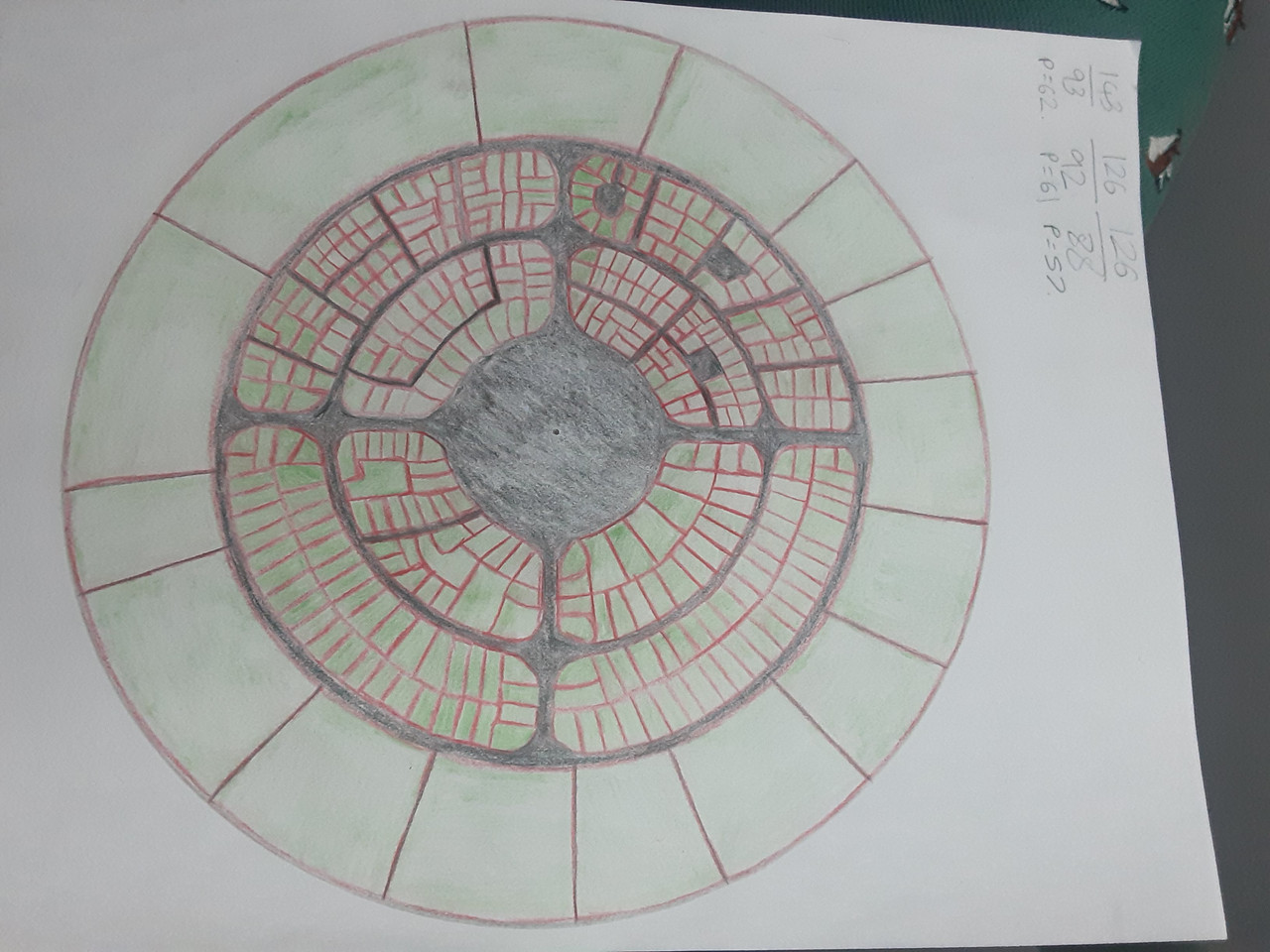
The red lines indicate the walls of individual buildings. The black shaded areas are roads, squares and the agora (in the centre). All roads are entirely pedestrian spaces. The two ring roads have a width of 2m for pedestrian traffic. The two straight roads that cross the agora have a minimum width of 3m. The streets widen at intersections. These are natural meeting places and will likely be the location of cafes, with extra seating spilling out onto the street.
The agora is a circular paved area some 50m in diameter at the centre of the town. Most days this will contain overspill outside seating from restaurants and bars. It will also host open air markets, Christmas events, theatre performances and is large enough to accomdate the entire population for town meetings.
All buildings are coloured green. This denotes the presence of roof gardens. Every building will host roof garden space. This will all be connected to form a continuous landscape, with foot bridges connecting all blocks above street level. This is important, because the street level of the town is extremely confined, with almost all of space taken up by buildings. The roof garden landscape provides an open green space that is open to all by ascending a spiral staircase from the street or from within buildings. These garden spaces will be places for recreation. This limits the stress of living within an otherwise crowded environment.
The buildings at the outer edge of the dome are large structures. They will include such things as sports facilities, gymnasium, schools, cinema, university departments, hotels, government buildings, public bathhouses and overspill accomodation. These will be constructed right up against the edge of the brick dome. The inner districts consist of smaller buildings. These will include terrace houses, as well as shops, bars, cafes and restaurants.
The whole town will be very densely inhabitated, due to the cost of constructing the dome. Houses will be small in footprint, but also tall. Flats may also be located above commercial premisses. How many people could live in this town? The medina in Fez, Morroco is a pedestrian city with a floor area ratio of about 1.5. It's population density is about 550/hectare. Our Martian town will have structures constructed on about 80% of internal land area, to a height of 5 floors. So floor area ratio is about 4. I will therefore conservatively assume about double the population density of the Fez medina. The area under the dome is 3.14 hectares, suggesting a population limit of some 3,500 people. The inclusion of underground spaces in addition to the roof garden, allows these people to spread out some more. It might be tolerable for some people to live in underground apartments, if they can climb a set of stairs into the town when they need open space.
#73 Re: Life support systems » Dust Mitigation Mars Solidified Regolith or Artificial Lichen » 2025-11-13 21:22:26
Teraforming would provide a solution here. If Mars is warmer and has an active hydrosphere, then the fines that are currently being blown about would end up as clay minerals in sediments. If Mars had a large sea anywhere on its surface, it would tend to eat up this dust, because dust could enter the sea, but would have no way of leaving once it did. It would tend to settle as mud at the bottom. But the atmosphere is too thin at present and temperatures too cold to allow a sea to form anywhere on Mars.
#74 Re: Science, Technology, and Astronomy » Suspension Bridge Martian City Roof Design » 2025-11-13 21:02:00
Basalt fiber has a tensile strength ranging from 2.8 to 3.1 GPa. This beats most maraging steels, for a material with only about 1/3rd the density! For larger castings, the strength is a lot less. This is likely because cooling introduces stress fractures into the material, which is quite brittle. Tensile stress must be kept sufficiently low to ensure that any stress fractures remain smaller than critical crack length. This allowable stress will be much lower than the UTS of the material. Still, the compressive strength of 300-500MPa is impressive.
I wonder if we could make rails out of this stuff? They would need a steel strip upper surface to interface with the wheels. But the compressive strength is plenty for a railway line. Food for thought. If this material cannot cope with thermal transients, then that would be its undoing on Mars. High manganese steel should retain ductility even at Martian nighttime temperatures. But the energy cost is much higher. Steel making on Mars will be much easier if we find fossil methane or hydrogen in traps beneath its surface. There are hints that that may be the case. But the presence of large deposits is speculative at this point,
#75 Re: Exploration to Settlement Creation » Calliban's Brick Dome on Mars » 2025-11-13 20:43:45
If the bricks are quite smooth, then a thin layer of epoxy glue could be used to bond them. If we assume a brick height of 10cm and a 1mm layer of epoxy glue, then we would need about 50 cubic metres for the whole dome. The glue would weigh about 50 tonnes. There are three potential challenges that I can see:
(1) As the dome rises, the work surface curves inwards. Beyond about 1/3rd of the way up, each new layer of bricks would need to be held in place whilst the glue sets.
(2) Mars is cold compared to most environments on Earth. Glue would be extremely stiff at temperatures <0°C. Setting time would be long, if indeed it sets at all. We may need to apply resistance heaters to keep the bricks and glue warm while the glue sets.
(3) Mars has an atmosphere with non-negligible pressure, which is a strong advantages over the moon. However, epoxy monomers are quite volatile. Will evaporation negatively impact the glue?
Assuming we can solve these problems, epoxy glue looks like the best approach. We could potentially produce a fine paste of epoxy glue and martian fines as a cement. That way, we can reduce the required mass of glue still further.