New Mars Forums
You are not logged in.
- Topics: Active | Unanswered
Announcement
#26 2025-05-17 02:21:25
- kbd512
- Administrator
- Registered: 2015-01-02
- Posts: 8,226
Re: SSTO Engine Technology
Dr Clark,
I decided to evaluate what an extendible / vacuum nozzle might net in terms of improved payload performance:
The Russian RD-0124 engine, a non-developmental LOX/RP1 engine in active service, has a vacuum Isp of 359s.
https://en.wikipedia.org/wiki/RD-0124
323.1s is 90% of that 359s Vacuum Isp
Mass Flow Rate (mdot) = Thrust / (Isp * g0)
3,452,113.5kg-f = 33,853,669N
mdot = 33,853,669N / (323.1 * 9.80665)
mdot = 33,853,669N / 3,168.528615
mdot = 10,684.35kg/s
6,508,946,390N-s / 33,853,669N = 192.267s
192.267s * 10,684.35kg/s = 2,054,248kg
Propellant Mass savings is 131,041kg, which nets an additional 7,407kg of payload to orbit. That amount of payload performance improvement would more than cover the mass allocation for the extendible nozzles. We need all the payload performance we can get for SSTOs, so I'll take it.
Offline
Like button can go here
#27 2025-05-17 06:32:16
- tahanson43206
- Moderator
- Registered: 2018-04-27
- Posts: 21,771
Re: SSTO Engine Technology
For kbd512 and RGClark ...
There must be a trade-off between the benefits of a variable geometry nozzle and just using two engines with the appropriate nozzles. All existing space access systems just use multiple engines instead of a variable geometry design.
It seems likely to me that the weight penalty of a second engine is pretty close to the weight any viable variable geometry scheme would have. GW Johnson has provided plenty (an abundance) of documentation on the challenges facing anyone who wants to try to create a variable geometry nozzle with known materials and techniques.
The second engine will need the plumbing to route fuel and oxidizer it's way, so that will definitely add mass.
Because it is possible readers of this post may not be familiar with GW's offerings, the bottom line is that the junction between the extension and the atmosphere bell is where a bit of tricky engineering is required.
GW tells me that if a vacuum engine is used for atmosphere propulsion, the tip will burn off right where the end of the atmosphere engine bell would be if the system were designed for atmosphere. If an extension is shifted forward to mate with the atmosphere bell, the junction is where the challenges will arise. GW seems to think it would be difficult to keep hot gases from burning through whatever seal your engineer team might come up with.
The hardware to shift the vacuum extension forward would have mass.
Why not simply design an SSTO with both engine types and eliminate the complexity of variable geometry?
The market opportunity I see is for a one person-to-LEO transport that is reusable, and a one way delivery of material comprising the vehicle itself to LEO for use in construction of a larger vessel such as the 500 passenger transport proposed by kbd512, or the 1000 person transport proposed by RobertDyck.
(th)
Last edited by tahanson43206 (2025-05-17 06:32:50)
Offline
Like button can go here
#28 2025-05-17 12:59:18
- GW Johnson
- Member
- From: McGregor, Texas USA
- Registered: 2011-12-04
- Posts: 5,994
- Website
Re: SSTO Engine Technology
The trouble with mixing two engine types in an SSTO is the very same problem SpaceX's "Starship" would have if one tried to make it an SSTO: you are too short on thrust to begin with, limited by what will fit behind the stage. Adding a second engine type just makes that even worse! You have to have enough thrust to launch "smartly", which is takeoff thrust/weight near 1.5 or more (never less), or your gravity is loss increases dramatically. Why? You end up burning the vast majority of your propellant in only the first ~5 km off the pad, leaving you still moving very subsonic!
Before the recent design updates, "Starship" was in the neighborhood of 120 tons inert and 1200 tons propellant if fully filled. At ZERO payload, that's a launch weight of 1320 tons. It is normally configured with 6 Raptor engines, 3 sea level in the neighborhood of 250-300 tons sea level thrust (call it 275), and 3 vacuum engines which would be nearer 150-200 tons thrust (call it 175), if unseparated at sea level, which strongly limits exit bell expansion ratio.
By the way, raising vacuum expansion ratio with constant chamber and flow rate makes the exit area bigger, so that fewer engines like that, will actually fit behind the stage! The takeoff thrust problem really gets unsolvable very quickly, if you attempt what might otherwise seem obvious!
Thrust is mdot*Vexit + (Pe - Pa)Ae, where the pressure term is quite strongly negative at sea level for an unseparated vacuum engine. (Thrust would be almost zero with a separated bell, which would further destroy itself in a single handful of seconds.)
Separation-limited vacuum engines (like the current vacuum Raptor) inherently have utterly-lousy sea level thrust! There is simply no way around that! 3x275 + 3x175 = about 1350 tons with all 6 burning at sea level on "Starship". That's thrust/weight only 1.02 at liftoff, which is long known to correspond to gravity losses WAY TO HELL-AND-GONE ABOVE 20% (or more) of LEO speed, not the 5% of an efficient system. Add only 30 tons of payload to this example, and this thing CANNOT budge a single inch off the launch pad, no matter how much propellant it has!
And there is NO ROOM behind it for more engines! Making the tankage hold 1300 or even 1400 tons really does not change that picture very much at all.
All SSTO designs face exactly the same thrust problem as trying to make an SSTO out of "Starship"! You cannot have any more engines, because those added would lie outside the stage diameter! That doubles-or-more your drag, and way-more-than-doubles your drag loss, which with a really clean shape of the right L/D ratio is about 5% of LEO speed.
There is simply way-far-more to this entire question than just Isp and mass ratio in the rocket equation! I have long tried to communicate that, but unsuccessfully!
And by the way, if sea level thrust gets reduced by the backpressure term, so does the corresponding sea level Isp, for the same combustion chamber design and total propellant flow rate. Which is EXACTLY why you need to look at engine/nozzle ballistics, and not just pull Isp's out of some table in some reference.
I have provided the spreadsheet tools and the instructional lessons, for free, to be able to do this work correctly. That's the stuff accessed by links posted right here on these forums.
GW
Last edited by GW Johnson (2025-05-17 13:29:10)
GW Johnson
McGregor, Texas
"There is nothing as expensive as a dead crew, especially one dead from a bad management decision"
Offline
Like button can go here
#29 2025-05-17 15:22:26
- kbd512
- Administrator
- Registered: 2015-01-02
- Posts: 8,226
Re: SSTO Engine Technology
tahanson43206,
The RL-10B-2 engine uses a RCC extendible nozzle. This nozzle extension is about the same size and weight as what a Vacuum-optimized Merlin requires. It appears as though the real payload benefit to a hypothetical Space Shuttle mass SSTO vehicle so-equipped, is no more than about 2,300kg, based upon the nozzle hardware mass required to equip 40 Merlin engines. That's more than what I thought it would be, and most of the mass appears to be the nozzle extension itself, rather than the deployment mechanism, which has almost negligible mass per engine. The extension hardware is only 10 to 20lbs per engine.
Apart from the cost of the nozzle extension, the nozzle mass increase pretty much kills this idea. You would get more useful payload by cutting the weight of each engine by using the same RCC material for all the major engine components, combined with a staged combustion cycle. The Merlin is a marvel of gas generator engine tech, but staged combustion always provides higher Isp.
That 116,120kg mass to orbit value is inflexible because 6,508,946,390N-s delivers 116,120kg to orbit. We know this because that was the Total Impulse provided by 3X RS-25 engines affixed to the Space Shuttle and 2X SRBs.
When I use Silverbird Astronautics Launch Vehicle Performance Calculator, this is what I get:
Inputs
Launch Vehicle: User Defined
Number of Stages: 1
Strap-on Boosters?: No
Dry Mass: 26,372kg
Propellant Mass: 2,185,289kg
Thrust: 33,854kN
Isp: 304.2s (90% of Vacuum Isp for the RD-180)
Default Propellant Residuals?: Yes
Restartable Upper Stage?: No
Payload Fairing Mass: 0kg
Launch Site: Cape Canaveral (USA)
Destination: Earth Orbit, Apogee 185km, Perigee 185km, Inclination: 45 degrees
Outputs
Launch Vehicle: User-Defined Launch Vehicle
Launch Site: Cape Canaveral / KSC
Destination Orbit: 185 x 185 km, 45 deg
Estimated Payload: 78,854kg
95% Confidence Interval: 58,892kg - 103,231kg
When the dry mass is adjusted downward to only 13,426kg (4,315kg RCC engines + same 9,111kg propellant tank mass)
Estimated Payload: 91,813kg
95% Confidence Interval: 71,844kg - 116,164kg
ISS orbit, same RCC engines:
Destination Orbit: 400 x 400km, 45deg
Estimated Payload: 86,900kg
95% Confidence Interval: 67,807kg - 110,215kg
ISS orbit, same RCC engines, 323.1s Isp (90% of RD-0124 Isp):
Estimated Payload: 108,038kg
95% Confidence Interval: 86,343kg - 134,287kg
This appears to be little better or worse than the real Space Shuttle if we added the hardware for resuability. The only measurable performance improvement achieved during the STS program came from making the External Tank lighter. These payload performance estimates confirm that a modestly better Isp from the same engines and propellant mass confers a meaningful payload performance advantage, but only when greater dry mass doesn't immediately replaces that useful payload mass.
Historical Space Shuttle GLOW and Propellant Mass: 2,032,096kg; 735,602kg LOX/LH2 plus 997,904kg APCP, 1,733,506kg total
SSTO Space Shuttle GLOW and Propellant Mass: 2,301,409kg; 2,185,289kg LOX/RP1
The historical Space Shuttle has a propellant mass reduction of 451,783kg, but both LH2 and APCP are much more expensive than RP1.
The SSTO Space Shuttle carries 587,443kg of RP1. The real Space Shuttle carried 106,261kg of LH2 and 159,665kg of solid fuel within the APCP oxidizer / fuel combo mixed into the propellant grain of the solid rocket boosters, or 265,926kg in total. The remainder of the solid propellant mass was AP oxidizer.
LOX: $0.27/kg
RP1: $2.30/kg
APCP: $5.00/kg
LH2: $6.10/kg
LCH4: $8.80/kg
Hydrazine: $75.80/kg
SSTO Space Shuttle Fuel Cost
LOX: 1,597,846kg * $0.27/kg = $431,418
RP1: 587,443kg * $2.30/kg = $1,351,119
Total Propellant Cost: $1,782,537
Historical Space Shuttle Fuel Cost
LOX: 629,341kg * $0.27/kg = $169,922
LH2: 106,261kg * $6.10/kg = $648,192
APCP: 1,733,506kg * $5.00/kg = $8,667,530
Total Propellant Cost: $9,485,644
That makes the propellant costs 5.3X cheaper for the SSTO Space Shuttle vs the real Space Shuttle, despite the fact that the SSTO Space Shuttle is burning 452t of additional propellant. Most of what the SSTO variant is burning is LOX. RP1 exhaust doesn't produce HCl, either, unlike APCP. We lacked the materials and engine tech necessary for any kind of SSTO when the real Space Shuttle was designed, so that's a moot point.
If whatever changes you're making to the vehicle lead to a greater dry mass, then you need more engine power and more propellant, period.
Offline
Like button can go here
#30 2025-05-17 15:25:51
- kbd512
- Administrator
- Registered: 2015-01-02
- Posts: 8,226
Re: SSTO Engine Technology
GW,
Is there any reason why you cannot have multiple turbopumps feeding propellants into the same combustion chamber (so that you can use a much larger nozzle without singular gigantic turbopumps)?
Offline
Like button can go here
#31 2025-05-18 06:49:53
- GW Johnson
- Member
- From: McGregor, Texas USA
- Registered: 2011-12-04
- Posts: 5,994
- Website
Re: SSTO Engine Technology
Kbd512:
There's no fundamental reason why you couldn't feed with from multiple turbopump assemblies. There might be a practical reason not to do that, though.
For the same flow velocities, flow rate should be proportional to cross section area, which suggests flow rate scales as pump dimension squared. Cutting down to half the flow in each pump would have those two assemblies each about 70% as large in dimension as the original single unit. That makes the packaging of the turbopumps about the engine chamber more crowded.
Since mass scales as dimension cubed, that option would be heavier, too.
I knew there was an extendible bell at least tested on some engine. From what you said, it was a variant of the RL-10. Did that ever fly on anything?
GW
Last edited by GW Johnson (2025-05-18 06:50:25)
GW Johnson
McGregor, Texas
"There is nothing as expensive as a dead crew, especially one dead from a bad management decision"
Offline
Like button can go here
#32 2025-05-18 15:47:01
Re: SSTO Engine Technology
Dr Clark,
I decided to evaluate what an extendible / vacuum nozzle might net in terms of improved payload performance:
The Russian RD-0124 engine, a non-developmental LOX/RP1 engine in active service, has a vacuum Isp of 359s.
https://en.wikipedia.org/wiki/RD-0124
323.1s is 90% of that 359s Vacuum Isp
Mass Flow Rate (mdot) = Thrust / (Isp * g0)
3,452,113.5kg-f = 33,853,669N
mdot = 33,853,669N / (323.1 * 9.80665)
mdot = 33,853,669N / 3,168.528615
mdot = 10,684.35kg/s6,508,946,390N-s / 33,853,669N = 192.267s
192.267s * 10,684.35kg/s = 2,054,248kgPropellant Mass savings is 131,041kg, which nets an additional 7,407kg of payload to orbit. That amount of payload performance improvement would more than cover the mass allocation for the extendible nozzles. We need all the payload performance we can get for SSTOs, so I'll take it.
Yes, that would offer significant improvement. The problem is with a variable nozzle it’s not certain the “90% rule” would still provide an accurate estimate. You would need to do an accurate trajectory sim to be sure.
Bob Clark
Old Space rule of acquisition (with a nod to Star Trek - the Next Generation):
“Anything worth doing is worth doing for a billion dollars.”
Offline
Like button can go here
#33 2025-05-18 16:02:06
Re: SSTO Engine Technology
tahanson43206,
…
Inputs
Launch Vehicle: User Defined
Number of Stages: 1
Strap-on Boosters?: No
Dry Mass: 26,372kg
Propellant Mass: 2,185,289kg
Thrust: 33,854kN
Isp: 304.2s (90% of Vacuum Isp for the RD-180)
Default Propellant Residuals?: Yes
Restartable Upper Stage?: No
Payload Fairing Mass: 0kg
Launch Site: Cape Canaveral (USA)
Destination: Earth Orbit, Apogee 185km, Perigee 185km, Inclination: 45 degreesOutputs
Launch Vehicle: User-Defined Launch Vehicle
Launch Site: Cape Canaveral / KSC
Destination Orbit: 185 x 185 km, 45 deg
Estimated Payload: 78,854kg
95% Confidence Interval: 58,892kg - 103,231kg,922
...
That mass ratio of nearly 100 to 1 may be too optimistic. The Falcon 9 first stage for instance gets about 20 to 1. You might be able to raise that to 30 to 1 using carbon-fiber tanks or the specialty high-strength steels on the Starship that SpaceX says matches carbon-fiber.
Bob Clark
Old Space rule of acquisition (with a nod to Star Trek - the Next Generation):
“Anything worth doing is worth doing for a billion dollars.”
Offline
Like button can go here
#34 2025-05-18 17:40:30
- kbd512
- Administrator
- Registered: 2015-01-02
- Posts: 8,226
Re: SSTO Engine Technology
Kbd512:
I knew there was an extendible bell at least tested on some engine. From what you said, it was a variant of the RL-10. Did that ever fly on anything?
GW
This Day in Aviation - 5 December 2014, 12:05 UTC
From the article:
The Delta IV Heavy’s second stage is 42.8 feet (13.05 meters) long, and is also 16 feet, 10.0 inches in diameter. It uses an Aerojet Rocketdyne RL-10B-2 engine, producing 24,750 pounds of thrust (110.09 kilonewtons) of thrust. The RL-10B-2 is 13.6 feet (4.15 meters) long, 7.0 feet (2.13 meters) in diameter, and weighs 611 pounds (277 kilograms).
It looks like it flew to me, 11 years ago now:
It's going to fly again, or actually, "again again" (since it's already flown once on SLS as well), with the SLS ICPS stage for Artemis II.
Edit:
RL-10B-2
According to this sales brochure from Pratt & Whitney, the RL-10B-2 engine first flew in space 1999 aboard a Delta-III. That was about 26 years ago, and it was used by the Delta-IV Heavy as an upper stage engine. I'm going to assume this is very well established technology at this point.
Last edited by kbd512 (2025-05-18 17:49:49)
Offline
Like button can go here
#35 2025-05-18 18:35:40
- tahanson43206
- Moderator
- Registered: 2018-04-27
- Posts: 21,771
Re: SSTO Engine Technology
Post for link to cutaway of Rl-10b-2 engine (Extendible nozzle engine) (in use since 1999 Delta 3 rocket)

Offline
Like button can go here
#36 2025-06-23 22:42:29
Re: SSTO Engine Technology
…
Separation-limited vacuum engines (like the current vacuum Raptor) inherently have utterly-lousy sea level thrust! There is simply no way around that! 3x275 + 3x175 = about 1350 tons with all 6 burning at sea level on "Starship". That's thrust/weight only 1.02 at liftoff, which is long known to correspond to gravity losses WAY TO HELL-AND-GONE ABOVE 20% (or more) of LEO speed, not the 5% of an efficient system. Add only 30 tons of payload to this example, and this thing CANNOT budge a single inch off the launch pad, no matter how much propellant it has!
And there is NO ROOM behind it for more engines! Making the tankage hold 1300 or even 1400 tons really does not change that picture very much at all.
All SSTO designs face exactly the same thrust problem as trying to make an SSTO out of "Starship"! You cannot have any more engines, because those added would lie outside the stage diameter! That doubles-or-more your drag, and way-more-than-doubles your drag loss, which with a really clean shape of the right L/D ratio is about 5% of LEO speed.
There is simply way-far-more to this entire question than just Isp and mass ratio in the rocket equation! I have long tried to communicate that, but unsuccessfully!
And by the way, if sea level thrust gets reduced by the backpressure term, so does the corresponding sea level Isp, for the same combustion chamber design and total propellant flow rate. Which is EXACTLY why you need to look at engine/nozzle ballistics, and not just pull Isp's out of some table in some reference.
I have provided the spreadsheet tools and the instructional lessons, for free, to be able to do this work correctly. That's the stuff accessed by links posted right here on these forums.
GW
Can your software calculate the ISP vs. altitude of a sea level Merlin engine given adaptive nozzles? This graphic shows a radical improvement over the standard Vulcain using altitude compensation:

Russian kerosene upper stage engines have reached a max 360s vacuum ISP. So the sea level Merlin given an adaptive nozzles would increase its vacuum ISP from 312s to 360s or above.
Note such an ideally adaptive nozzles would also increase the sea level ISP, as the graphic shows for the Vulcain engine. The reason is fixed nozzle sea level engines are always overexpanded at sea level. This is because the engine designer also wants good performance in vacuum, so they select some intermediate expansion value. This reduces the sea level performance.
Note this means the adaptive nozzles also increases the sea level thrust over the standard engine. Then the adaptive nozzle has the twin benefit of increasing the vacuum ISP as well as reducing gravity drag due to increased thrust.
Bob Clark
Last edited by RGClark (2025-06-23 23:22:14)
Old Space rule of acquisition (with a nod to Star Trek - the Next Generation):
“Anything worth doing is worth doing for a billion dollars.”
Offline
Like button can go here
#37 2025-06-24 09:45:32
- kbd512
- Administrator
- Registered: 2015-01-02
- Posts: 8,226
Re: SSTO Engine Technology
Dr Clark,
How would you go about building an engine nozzle capable of changing its shape in 3 dimensions to match that 1D theoretically ideal expansion vs altitude graph, even now that we have lightweight materials able to withstand exhaust heat without regenerative cooling?
This is because the engine designer also wants good performance in vacuum, so they select some intermediate expansion value.
To the extent feasible, I would imagine that engine designers bias the nozzle expansion ratio toward the lower bound of the altitude range where the engine spends most of its firing time. If you spend far less time below 30,000ft than you do above 30,000ft, then it makes a lot more sense to optimize the nozzle's expansion ratio for 1/3rd of sea level pressure, however much you can get away with before significant flow separation occurs at sea level.
Offline
Like button can go here
#38 2025-06-24 13:55:50
- GW Johnson
- Member
- From: McGregor, Texas USA
- Registered: 2011-12-04
- Posts: 5,994
- Website
Re: SSTO Engine Technology
Rocket nozzle thrust is F = CF At Pc, where Pc is understood to be the chamber pressure before flow starts necking down into the nozzle throat. Further, it is presumed that area contraction ratio is near 10, so that static pressure and total pressure at the Pc station are indistinguishable.
Here is the most convenient form of the CF equation: CF = (Ae/At)(Pe/Pc)(1 + g nKE Me^2) - (Pa/Pc)(Ae/At), in which Ae/At is the nozzle expansion ratio, Pa is the ambient backpressure, g is the specific heat ratio, nKE is the nozzle kinetic energy efficiency, and Pe is the expanded pressure in an unseparated nozzle, even if it is over-expanded.
There are two terms in CF: the first one (which is actually the vacuum CF) depends ONLY upon the expansion ratio Ae/At, which sets Me and Pe/Pc, for any given g, plus a value for nKE matching the detailed nozzle geometry. Me usually has to be determined iteratively from Ae/At. Once you know Me, you know everything: the compressible formulas are given in terms of Me and g, for Pe/Pc and for Ae/At.
The second term also depends upon Ae/At, but explicitly depends upon the actual values of Pc as well as Pa. This is the backpressure correction term for the retarding effects of being immersed in an atmosphere at some Pa. It is exactly zero in vacuum, because in vacuum Pa = 0 by definition.
The old standard sea level designs always used 1 atm for Pa, and set the expansion ratio Ae/At such that Pe = Pa. The backpressure term is significant: there is always less thrust at sea level, than out in vacuum, all else being equal. These Pe = Pa sea level nozzles have all the thrust you are going to get at sea level, but only somewhat more in vacuum, because the Pe = Pa design limits your expansion ratio rather strongly. It is the Pe = Pa design approach that makes Isp sensitive to Pc, via that backpressure term.
You can use any of a variety of larger expansion ratios at sea level, as long as you do not separate the bell due to excessive Pa compared to Pe. When you do that, the thrust you get at sea level reduces below the old-time sea level design’s thrust, but the vacuum thrust you get with it is larger, because the expansion ratio is larger. That increases the average ascent Isp of the nozzle, flying from sea level out into vacuum, but the cost for that is the reduced thrust at sea level, just at the time when you are the very heaviest at launch, trying to fly straight upward against gravity!
The dilemma is that you are always short of thrust at launch, limited by how many engines of a given thrust will actually fit behind the stage. I cannot emphasize that enough! It is why just “doing the rocket equation” will ALWAYS lead you astray when you do actual design sizing work.
The limit for separation is determined by any of a number of empirical (!!!!) correlations over the years. The one I like is very simple to use, and determines Psep/Pc = (1.5*(Pe/Pc))^0.8333. At any given design with a specific Pc value, you then know the value of Psep. If Pa > Psep, the bell separates (and is usually destroyed in a matter of a few to only several seconds). As long as Pa < Psep, there is no separation, although the backpressure term at sea level does strongly reduce your CF because of the larger Ae/At, and thus your thrust.
The trend in recent years toward higher Pc values is easily explained looking at the thrust equation F = CF At Pc. At the same expansion ratio and CF, higher Pc lets you use a smaller At for the same thrust F! Smaller At is smaller Ae and smaller engine length. More of these higher-Pc engines will fit behind the stage, getting you more thrust at sea level launch when you need it the most.
And, yes, Bob, you can use my spreadsheet to model that extendible-bell RL-10 variant. Run the sea level design and determine the flow rate and throat area. Then re-run the problem with the bigger expansion as a vacuum design, and adjust your vacuum thrust sizing value until you get exactly the same flow rate and throat area as the sea level design. Pick an altitude to do the switch-over. Use the sea level's performance data vs altitude up to that point, then use the vacuum's performance data vs altitude from that point on up to vacuum. Then combine those data into one plot. Do the averaging of Isp across altitude with the same two sets of data, but combined into one set at the switch-over altitude, and that’s a pretty good approximation to the ascent-averaged Isp you would see.
No, it is complicated, you simply don't do this with a single or simple calculation. It takes lots of calculations, which is exactly what the spreadsheet does for you. But you can do it.
GW
GW Johnson
McGregor, Texas
"There is nothing as expensive as a dead crew, especially one dead from a bad management decision"
Offline
Like button can go here
#39 2025-06-24 16:23:12
- GW Johnson
- Member
- From: McGregor, Texas USA
- Registered: 2011-12-04
- Posts: 5,994
- Website
Re: SSTO Engine Technology
I took a look around at several sites regarding the RL-10B-2 with the extendible exit cone. I did find it was only used as an upper stage vacuum engine. The stowed nozzle allows it to fit in a shorter interstage space, but it is not fired that way! The ONLY data for it are in the extended vacuum configuration. That's not to say a 2-piece extendible nozzle could not be designed and developed, but the RL-10B-2 is NOT one of those!
Most applications have more interstage length available, which is why the other variants, including the newer RL-10C's, have fixed geometry vacuum nozzles. It's only used for upper stage service as a vacuum engine these days. The low-expansion RL-10A's are all long-retired.
GW
GW Johnson
McGregor, Texas
"There is nothing as expensive as a dead crew, especially one dead from a bad management decision"
Offline
Like button can go here
#40 2025-06-29 15:34:59
Re: SSTO Engine Technology
Thanks, GW for the discussion of getting the Isp vs. altitude with adaptive nozzles. I’ll give it a try to see if I can get it to work. I suppose I can test my calculations by first doing it for the Vulcain engine and seeing if I get the same results as that graphic.
In regards, to the extended nozzle being too large for the rocket diameter, there are other ways of doing the altitude compensation. For instance what’s key is the expansion ratio has to vary. This can be done by keeping the nozzle fixed but varying the nozzle throat. This was done for the ASALM ramjet missile for example.
Bob Clark
Old Space rule of acquisition (with a nod to Star Trek - the Next Generation):
“Anything worth doing is worth doing for a billion dollars.”
Offline
Like button can go here
#41 2025-06-29 22:41:01
- GW Johnson
- Member
- From: McGregor, Texas USA
- Registered: 2011-12-04
- Posts: 5,994
- Website
Re: SSTO Engine Technology
I was on the team that did the variable geometry nozzle work for ASALM. It was not about altitude compensation. It was for lowering inlet supercritical margin in leaned-back cruise. We did it with a lollipop in the ramjet throat, that turned streamline for the big throat area, and turned broadside for the smaller throat area.
Key to making it function at a good nozzle kinetic energy efficiency is making sure the lollipop wake closes by the time the nozzle exit is reached. That must be true in both positions, but is more difficult to achieve when broadside. Nozzle kinetic energy efficiency with the lollipop done right is about 94-95%, in a nozzle bell that otherwise would be about 98.3%. Screw that flow pattern up and it drops down nearer 80% or worse.
The throat area modulation was fairly low ratio (about 2:1), and only those two positions were allowed. It only worked at the rather low chamber pressures of the ramjet (under 200 psia). Alloy steel covered in silica phenolic ablative. We did a 900 sec burn in ground test, and it still worked at the end of that burn. This technology never flew. The missile prime determined that the higher cruise efficiency with lower supercritical margin was not worth the extra weight and lowered nozzle efficiency (even though the loss was only from 98.3% to 94-95%).
GW
Last edited by GW Johnson (2025-06-29 22:43:34)
GW Johnson
McGregor, Texas
"There is nothing as expensive as a dead crew, especially one dead from a bad management decision"
Offline
Like button can go here
#42 2025-07-01 07:55:45
Re: SSTO Engine Technology
I was on the team that did the variable geometry nozzle work for ASALM. It was not about altitude compensation. It was for lowering inlet supercritical margin in leaned-back cruise. We did it with a lollipop in the ramjet throat, that turned streamline for the big throat area, and turned broadside for the smaller throat area.
…
GW
Can you explain what the supercritical margin referred to? Also, there are variations of this idea of restricting the throat size while keeping the nozzle itself fixed such as the expansion-deflection nozzle:
Another possibility is not to have a physical restriction but to have fuel injection openings around the throat to inject fuel at high pressure to thereby reduce the throat size for the combusted gas to flow through.
Bob Clark
Old Space rule of acquisition (with a nod to Star Trek - the Next Generation):
“Anything worth doing is worth doing for a billion dollars.”
Offline
Like button can go here
#43 2025-07-01 10:00:24
- GW Johnson
- Member
- From: McGregor, Texas USA
- Registered: 2011-12-04
- Posts: 5,994
- Website
Re: SSTO Engine Technology
ASALM was a ramjet. When you lean down to lower thrust for efficient cruise, the combustor pressure drops a little, which means the inlet pressure drops a little. When that happens, the terminal inlet normal shock lies deeper down the inlet's divergent diffuser section, where it takes place at a higher Mach number and is therefore stronger with a larger total (stagnation) pressure loss. That lowers cruise Isp a little from the higher level that leaning-down provides.
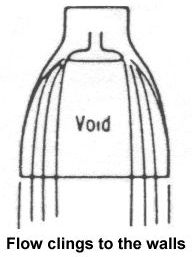
The sketch showing flow "clinging to the walls" is not quite right as it is drawn. There is a "cling to the walls" effect, but there is also a separated wake closure effect that is not at all depicted in the sketch.
This is because of Prandtlt-Meyer expansions and oblique shock compressions and changes of direction. It will over-expand around the obstruction, then where those flows collide on centerline, oblique shocks straighten the flow back out to axial. The more 3-D the obstruction shape, the more complicated the flow pattern.
If you can achieve obstruction wake closure before reaching the bell exit plane, your nozzle kinetic energy efficiency stays high, although not quite as high as a "clean" nozzle with no throat obstruction to create a wake. If you do not achieve closure before reaching the exit plane, your nozzle kinetic energy efficiency drops precipitously!
The low kinetic energy efficiency multiplies the Mach number squared term in the CF equation, which is where most of your thrust comes from. We verified this in flow visualizations, cold flow tests, and hot firing ramjet tests with Shelldyne-H fuel (also known as RJ-5) and heated air.
Injecting fuel near a ramjet throat has no chance of being successful! You might as well just dump it overboard, because it has no chance to burn. The combustor residence time of 2 to 3 msec is just barely enough to get around 95% of the fuel injected in the inlet burnt. From throat to exit plane the residence time is a tiny fraction of a msec.
Besides, the injected fuel streams will have no perceptible effect on the gas flow pattern through the throat, for two reasons: (1) the fuel mass flow is tiny compared to the air mass flow, even if you inject ALL of the fuel there, which you cannot, and (2) the volume of the fuel stream is exceedingly tiny compared to the volume of the air stream, precisely because the density of the liquid is much higher than the gas, and the mass flow of fuel is so small compared to the air.
GW
GW Johnson
McGregor, Texas
"There is nothing as expensive as a dead crew, especially one dead from a bad management decision"
Offline
Like button can go here
#44 2025-07-02 01:34:02
Re: SSTO Engine Technology
…
Injecting fuel near a ramjet throat has no chance of being successful! You might as well just dump it overboard, because it has no chance to burn. The combustor residence time of 2 to 3 msec is just barely enough to get around 95% of the fuel injected in the inlet burnt. From throat to exit plane the residence time is a tiny fraction of a msec.Besides, the injected fuel streams will have no perceptible effect on the gas flow pattern through the throat, for two reasons: (1) the fuel mass flow is tiny compared to the air mass flow, even if you inject ALL of the fuel there, which you cannot, and (2) the volume of the fuel stream is exceedingly tiny compared to the volume of the air stream, precisely because the density of the liquid is much higher than the gas, and the mass flow of fuel is so small compared to the air.
GW
About injection fuel or oxidizer or even inert gas like nitrogen horizontally from around the sides of the throat, I’m not intending this to burn. It is simply to constrict the size of the area the already combusted gases can pass though to the nozzle. It would be at comparable pressure or higher to how the propellant is injected into the combustion chamber from the feed lines.
Bob Clark
Old Space rule of acquisition (with a nod to Star Trek - the Next Generation):
“Anything worth doing is worth doing for a billion dollars.”
Offline
Like button can go here
#45 2025-07-02 08:33:53
- GW Johnson
- Member
- From: McGregor, Texas USA
- Registered: 2011-12-04
- Posts: 5,994
- Website
Re: SSTO Engine Technology
There were two variable throat area technologies that I worked on long ago.
One was the rotating "lollipop" for the ASALM variable geometry nozzle option that was not flown. It could have, but the prime did not choose to do that. That is the technology described in the posts just above. It was survivable at ramjet throat conditions, but would not be survivable at rocket throat conditions, where the higher pressure drop would drive larger shear forces that would strip the silica phenolic ablative right off the steel. This also shows up in the fact that monolithic silica phenolic nozzles work well in ramjets, but not in rockets, which needed a hard graphite throat insert instead.
The other was a side-inserted pintle into a throat tube, for the fuel-flow throttle valve of a gas generator-fed ramjet. The fuel-rich solid propellant's effluent stream was the fuel to be burned with air in the combustor. This was a successful technology, and while ours did not fly in a ramjet AMRAAM, something similar to it is flying today in the European "Meteor" missile, which is a very similar gas generator-fed ramjet. Ours did fly in the USN "Coyote" gunnery target drone, after our plant got closed.
It was the relatively cool and reducing environment of the fuel stream that allowed us to make the pintle and the throat tube out of TZM alloy, despite the high solids content and its gritty erosive nature. There was a sort of tower out the side of the throat tube that contained a stack of graphite heat sink rings, which pulled enough heat out of the pintle to allow a gas seal to survive at the cool end of it. This tower's shell was part of the pressure vessel. This thing worked on a transient only, with about a 2 minute capability, at 1700-2500 F gas temperatures, and upstream chamber pressures from 50 to 2200 psia. The cool end of the tower is where the motion servo and measuring gear were mounted. The TZM had a ~4000 F meltpoint, but would oxidize away rapidly if there was any oxygen present.
This was a fuel throttle for massflow control of the solid gas generator burn. It had nothing to do with producing thrust. The smaller the net throat area, the higher the equilibrium pressure, and the higher the flow rate. The flow about the pintle was wildly 3-D, with a wake zone and oblique shocks. The shock-impingement and associated amplified heating upon the throat tube were handled by the TZM, but there was silica phenolic ablative between it and the surrounding pressure shell. This thing led to a showerhead-type fuel injector, which had to be specifically designed for very high subsonic internal flow speeds, in order that the hole sizes would still help direct how much fuel effluent went where. I got the patent for that.
This sort of thing might be at least theoretically used to vary the throat area of a rocket, but the cooling requirements will be enormous. The gas temperatures are well above the meltpoint of TZM, and there will likely be oxygen present at low concentrations, ruling out the use of that alloy. The very high chamber pressures (3000-5000 psia) will stress the thing severely. And there is the wildly-3-D flow field downstream of the pintle. That will really mess up the expansion-for-thrust in the bell. And if the pintle wake does not close before the exit plane, you have the same massive thrust inefficiency problem that I already described for the ASALM lollipop.
The pintle throat was never developed or tested for rocket nozzle application, only the fuel effluent throttle for a fuel-rich solid propellant gas generator (which is a misnomer because of the high solids content in the effluent). The "lollipop" was tested, but only at ramjet conditions. It was developed to the point of readiness for experimental flight test. The pintle was also developed to the point of readiness for experimental flight test, but only at those gas generator conditions, and for a showerhead injector, not a thrust-producing expansion.
Both of these were "one shot" missile designs, not anything to be reusable. These technologies were very difficult development items, even though they were restricted to their less challenging applications.
GW
Last edited by GW Johnson (2025-07-02 09:06:34)
GW Johnson
McGregor, Texas
"There is nothing as expensive as a dead crew, especially one dead from a bad management decision"
Offline
Like button can go here
#46 2025-07-02 09:13:34
- GW Johnson
- Member
- From: McGregor, Texas USA
- Registered: 2011-12-04
- Posts: 5,994
- Website
Re: SSTO Engine Technology
You can make injection at the throat more feasible by injecting already-hot gas as your throat streams. At comparable densities, the volume blocking effect is maximized. You might get a few percent throat area modulation out of that, but I rather doubt the percentage would be large. Such a concept would need experimental verification in some sort of experimental test. You would also have to face the weight and volume penalties of a device capable of producing a variable hot gas stream on command, of significant mass flow relative to the overall engine massflow.
To the best of my knowledge, nothing like that has ever been attempted. The closest analog would have been injection into the supersonic bell for thrust vectoring effects. It sort-of works, but was not attractive enough for anybody to ever fly it. Gimballing was far more effective for the weight and volume.
GW
GW Johnson
McGregor, Texas
"There is nothing as expensive as a dead crew, especially one dead from a bad management decision"
Offline
Like button can go here
#47 2025-07-05 06:45:19
- tahanson43206
- Moderator
- Registered: 2018-04-27
- Posts: 21,771
Re: SSTO Engine Technology
For all...
GW's work posted in the exrocketman.blogspot.com site is now available by a single click.
https://exrocketman.blogspot.com/search?q=ssto
The paper is detailed, with plenty of graphs to illustrate the text.
I am guessing here, but it is possible that anyone offering an opinion without reading the paper is indeed likely to be missing something important.
(th)
Offline
Like button can go here