New Mars Forums
You are not logged in.
- Topics: Active | Unanswered
Announcement
#1 2025-05-26 04:21:35
- kbd512
- Administrator
- Registered: 2015-01-02
- Posts: 8,174
Long Duration LH2 Propellant Storage Challenge
During our Sunday meeting, tahanson43206 asserted that the Sun shield technology created for the James Webb Space Telescope (JWST) would enable passive long duration storage of hard cryogens such as LH2, apparently based upon the belief that the Sun shade was able to passively keep a scientific instrument cooled to 7K. This is not accurate, according to NASA, but he asked me to write a post to pose the question to The New Mars Forums readership to evaluate how closely a similar Sun shade system would enable us to come to passive LH2 storage.
Webb's Sunshield - NASA Science
My assertion or opinion is that trying to use JWST as a proxy or analog for the kind of cryogenic cooling systems (passive and active) required for long duration LH2 storage for a crewed Mars mission ignores the problems of location (LEO vs L2), scale (many tons of propellant vs mere kilos of LN2 and LHe2 for scientific instruments), and mass (because ALL rocket stages need to minimize structural mass and maximize propellant mass). I don't consider that last point to be debatable in any real sense due to "The Tyranny of the Rocket Equation".
However, I'm not content with merely illustrating that JWST does not actually keep the operating temperatures of shaded instruments at or below the 20K required by LH2, using passive means only. That's not an intellectual argument which demonstrates any fundamental underlying truth about the validity of the idea of long duration LH2 storage propulsion stages using some combination of passive and active cooling to provide a meaningful payload performance improvement for an in-space propulsion stage, relative to softer cryogens such as LOX/LCH4 or LOX/RP1. I consider a meaningful payload performance improvement to be 10% or greater. If we can achieve a 10% greater "throw weight" to the moon or Mars or other destination in the solar system, provided the solution is not absurdly expensive, complex, or delicate, I would chalk that up as a major "win" for LH2 or any other technology that does the same job. If the "throw weight" advantage is less than a 10% improvement, then we need scrupulous evaluation of cost. Is a 5% payload performance improvement worth the cost? The answer to that question is, as with most trade-offs, is, "it depends". Regardless, engineering over ideology, forever and always.
Use of effective lightweight thermal insulation and vacuum between layers is at least a partial solution, insofar as multi-layer Mylar insulation is very light and dramatically reduces the thermal load from direct solar radiation from the Sun or re-radiation from the Earth (rejection of solar radiation back into space), onto the cryogenic propellant storage tanks. Unfortunately, as we're about to discover, passive Mylar insulation alone is insufficient to achieve the 20K storage temperature LH2 requires to remain liquid. Achieving 20K temperatures in the inner solar system requires more layers of Mylar than JWST used and power-hungry cryocoolers, photovoltaic panels for electrical power to run the cryopumps, pump motors, heat exchangers, and cryoradiators (chemically milled or 3D printed monolithic Al-1350 alloy with 99.999% purity, which is what JWST used), all of which adds significant dry mass and cost to LH2 propulsion systems with so-called Zero Boil Off (ZBO) technology incorporated. If we can somehow justify the added mass and expense with a substantial payload performance advantage, then it might still be worth it.
ULA has proposed using 20-25 layers of Mylar for LH2 orbital propellant depots vs the 5 layers of Mylar used by the JWST, as well as cryocoolers to reject the rest of the the thermal load. This was for a minimal boil-off, rather than a true ZBO solution. The mass of Mylar insulation and the pneumatic deployment mechanism to move the insulation layers away from the LH2 tank was a significant fraction of a Centaur upper stage propellant tank's inert mass. Centaur upper stages use chemically milled stainless steel so thin that it collapses under its own weight here on Earth, and is kept inflated using internal pressurization. However, ye olde cube-square law would enable us to use tank geometry to minimize Mylar insulation mass vs tank mass. All that is to say that a Centaur upper stage is sub-optimal for an in-space ZBO propulsion stage using LH2 fueled RL-10 engines. However, Centaur is famous for its exceptional propellant mass fraction- some 95% of total stage mass. That means it's pretty difficult to design a substantially lighter upper stage or in-space stage.
Note:
I typically refer to these thin Aluminized polymers as "Mylar" (polyester), but in point of fact JWST uses Aluminized Kapton (polyimide) film. To my knowledge, both materials have been used as Multi-Layer Insulation (MLI) surrounding cryogenic storage equipment. Kapton is more thermally stable at higher temperatures. The specific Kapton that JWST used may or may not have had other dopants applied to modify its optical properties, such as Gold or Silicon, but truthfully I haven't read much about JWST due to lack of interest. I haven't even read all the info on the NASA Science article I linked to for that reason.
From the NASA Science Article:
Cooling to Operating Temperatures
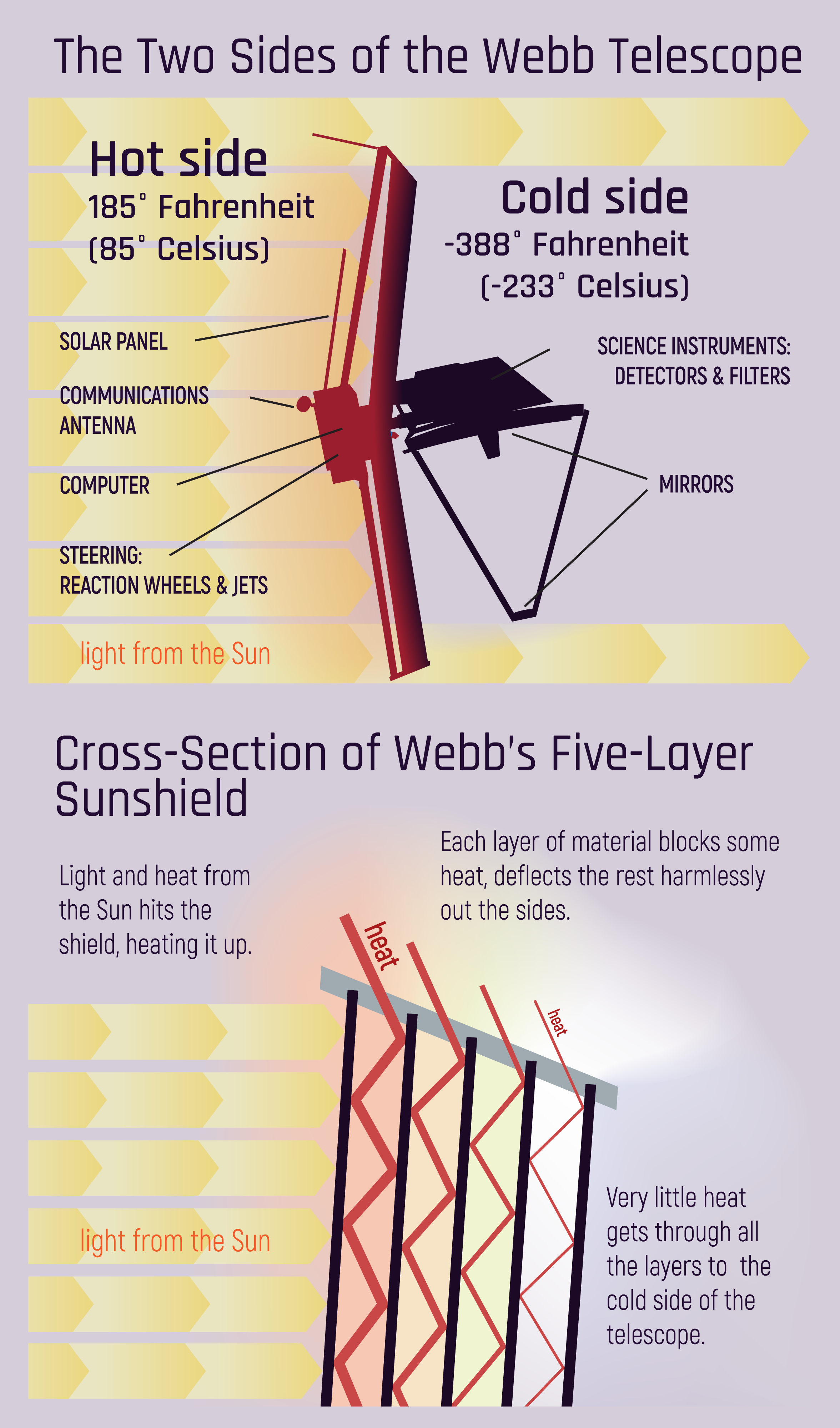
The sunshield separates the observatory into a warm, sun-facing side ( with maximum temperature modelled at the outermost layer of 383K or approximately 230 degrees F), and a cold side (with the coldest layer having a modeled minimum temp of 36K or around -394 degrees F). The telescope requires temperatures under 50K (~-370F) to operate.After launch and deployment, the sunshield allowed the telescope to cool down to required operating temperatures and remain stable below 50 Kelvin (-370°F, or -223°C) by passively radiating Webb's heat into space. The near-infrared instruments (NIRCam, NIRSpec, FGS/NIRISS) work at about 39 K (-389°F, -234°C) through a passive cooling system. The mid-infrared instrument (MIRI) requires colder temperatures that require reaching a temperature of 7 K (-447°F, -266°C), using a helium refrigerator, or cryocooler system.
This NTRS doc explains the finer points of the cryogenic systems aboard JWST:
James Webb Space Telescope Core 2 Test - Cryogenic Thermal Balance Test of the Observatory’s 'Core' Area Thermal Control Hardware
The James Webb Space Telescope (JWST), successor to the Hubble Space Telescope, will be the largest astronomical telescope ever sent into space. To observe the very first light of the early universe, JWST requires a large deployed 6.5-meter primary mirror cryogenically cooled to less than 50 Kelvin. Three scientific instruments are further cooled via a large radiator system to less than 40 Kelvin. A fourth scientific instrument is cooled to less than 7 Kelvin using a combination pulse-tube Joule-Thomson mechanical cooler. Passive cryogenic cooling enables the large scale of the telescope which must be highly folded for launch on an Ariane 5 launch vehicle and deployed once on orbit during its journey to the second Earth-Sun Lagrange point. Passive cooling of the observatory is enabled by the deployment of a large tennis court sized five layer Sunshield combined with the use of a network of high efficiency radiators. A high purity aluminum heat strap system connects the three instrument's detector systems to the radiator systems to dissipate less than a single watt of parasitic and instrument dissipated heat. JWST’s large scale features, while enabling passive cooling, also prevent the typical flight configuration fully-deployed thermal balance test that is the keystone of most space missions’ thermal verification plans. This paper describes the JWST Core 2 Test, which is a cryogenic thermal balance test of a full size, high fidelity engineering model of the Observatory’s ‘Core’ area thermal control hardware. The 'Core' area is the key mechanical and cryogenic interface area between all Observatory elements. The ‘Core’ area thermal control hardware allows for temperature transition of 300K to ~50 K by attenuating heat from the room temperature IEC (instrument electronics) and the Spacecraft Bus. Since the flight hardware is not available for test, the Core 2 test uses high fidelity and flight-like reproductions.
Long Duration Mission LH2 In-Space Propulsion Stage Grand Challenge
Can anyone here execute an engineering design exercise for a LOX/LH2 ZBO in-space propulsion stage, using existing engine tech, whereby they can demonstrate a 10% or greater payload performance improvement?
Ground Rules
1. Scale your proposed in-space LH2 fueled propulsion solution to deliver 100 metric tons of payload to the moon or Mars, since those are the most likely destinations for vehicles using this new propulsion technology. You may borrow as much tech design from existing concepts as you require. If ULA or NASA or ESA have already thought up roughly appropriate solutions, then there is no need to reinvent the wheel to prove the worth of your design concept, provided that the following design constraints are met:
2. You must use existing LH2 fueled engine designs already optimized for in-space propulsion. There will be no invocation of miraculous new engine technologies that have never flown in space. If and when such engines actually fly in space, then you may assert improved performance using the new engine design. Existing in-space engines include ESA's Vinci, Aerojet-Rocketdyne's RL-10 and J-2. If you require more thrust, then you must use additional engines. The SLS cryogenic propulsion stage uses 4X RL-10B-2 engines providing 465.5s of Isp and 110.1kN of thrust per engine, for example. The absolute highest Isp LH2 upper stage / in-space engine was the Russian RD-0146, with a claimed 470s Isp. It's unreasonable to assume any new engine will provide significantly more Isp than that one. Feel free to trade-off Isp, engine mass, and propellant mass in whatever way provides the greatest payload performance advantage for your proposed design. You are limited by maximum single burn duration because that correlates with engine nozzle life for the uncooled nozzle extension. If your design's thrust is too low, then you must add engines until the single firing design life limit of the engine is met. You are also limited by the maximum number of engine restarts if you intend to use a gravity assist to improve performance. IIRC, the RL-10 can be restarted a maximum of 15 times.
3. No invocation of miracle materials to reduce the mass of the propellant tanks, insulation, radiator, photovoltaics, cryocoolers, or related systems. There will be no atomically-thin Graphene radiators, 4-layer VentureStar CFRP propellant tanks that leaked like sieves, or similar silliness. You may add as many layers of MLI as you want, whether Mylar or Kapton or any other material already used for that purpose. Due to packaging constraints, the photovoltaics will be deployable arrays, Silicon wafer or CIGS thin films, whichever best serves to minimize the mass of the power generating equipment for your cryocoolers. If using more thin film photovoltaics and more powerful cryocoolers actually reduces stage mass vs attempting to adding more layers of insulation, then do what works best. Any existing Aluminum or stainless steel alloy suitable for cryogenic propellant storage may be used. For composite LH2 tanks, stick with IM7 fiber and Cycom 5320-1 resin. Using materials tech that NASA or launch services providers have exhaustively tested and actually flown in space during robotic or crewed missions makes your design choices and material selections look reasonable and realistic.
Next Generation Multilayer Insulation with Discrete Spacer Technology
4. The stage storage period is set at 6 months. During that period of time, if you had no insulation and no cryocoolers, then most or all of your LH2 would have boiled off. Your boil off rate goes down as you add MLI and cryocooler power to keep your LH2 frosty. ULA and NASA have excellent documentation on daily LH2 boil-off rates, which affect the RL-10 powered Centaur upper stages used for high Delta-V military and exploration missions.
Centaur Extensibility For Long Duration
THERMAL PERFORMANCE OF A MODULARIZED REPLACEABLE MULTILAYER INSULATION SYSTEM FOR A CRYOGENIC STAGE
5. Your competition will be subject to the same basic rules regarding the use of existing engines and materials, but will instead use LOX/LCH4 or LOX/RP1. If you can demonstrate a 10% or greater payload performance to the moon or Mars, then your LH2 design wins. If you cannot, then the Hydrocarbon solution wins. All designs are limited by existing launch vehicle designs and will start in LEO. For practical purposes, tank geometry is limited to 1.5X the diameter of the rocket stage it's attached to. Starship has a second stage diameter of 9m, so a 13.5m diameter LH2 tank is the practical limit of assistance that cube-square will assist with reducing propellant tank mass per unit of LH2 volume.
Starting from higher orbits requires more propellant, so there will be no "Well, I chose to start in GEO" silliness, either. You may assume that a Starship-like vehicle will be able to deliver 200t to LEO. If you go over the payload performance of this existing launch vehicle, then you require 2 launches. Since on-orbit cryogenic propellant transfer has yet to occur, we're limiting ourselves to complete stages launched to orbit. If your LH2 fueled design solution requires the same number of launches to deliver your in-space propulsion stages vs a Hydrocarbon solution, then we have a draw. Launches services tend to be the most expensive part of space travel, so anytime we need the exact same number of launches to deliver the same amount of "oomph" to our payload, the benefits of Solution A vs Solution B tend to revolve around total launch cost. It's improbable that a more technically advanced solution requiring the exact same number of launches as a lower-tech solution reduces total mission cost.
Tahanson43206 thinks that I'm eventually going to "come around" to this idea of using LH2 propulsion, but I've yet to read about a case where a LH2 solution provided a clearly definable technical advantage. I'd much rather steel-man his argument about the superiority of LH2 over lower-Isp hydrocarbon fuels, rather than dismiss the idea entirely. I'll give him and everyone else as much ammunition as I can to help them make their case, but then it's up to them to make the case convincingly.
F9 = Falcon 9
F9H = Falcon 9 Heavy
D4 = Delta IV
D4H = Delta IV Heavy
CBC = Delta IV Heavy Common Booster Core
F9 Booster (LOX/RP1; 9X Merlin-1D engines): 22,800kg to LEO (no reusability); 23,600kg booster dry mass (no landing gear)
F9 Upper Stage (LOX/RP1; 1X Merlin-1D Vacuum engine): 3,900kg stage dry mass
F9 Payload to Mars: 4,020kg
F9H Payload to Mars: 16,800kg
F9H Wet Mass: 1,420,788kg
F9H Dry Mass: 74,700kg
D4H Booster (LOX/LH2; 3X RS-68A engines): 28,790kg to LEO (no reusability); 78,400kg booster dry mass
D4/D4H DCSS Upper Stage (LOX/LH2; 1X RL-10B-2 engine): 3,480kg stage dry mass
D4H CBC Dry Mass: 26,000kg
D4H Core Dry Mass: 26,400kg
D4H Payload to Mars: 8,000kg
D4H Wet Mass: 733,000kg
D4H Dry Mass: 81,880kg
Propellant Tank Fabrication Material: Al-2195 (F9 / F9H and D4 / D4H)
Booster Engine Cycle: Gas Generator (F9 / F9H Merlin-1D and D4 / D4H RS-68A)
Booster Engine Isp (sl): 366s (RS-68A); 311s (Merlin-1D)
Upper Stage Engine Cycle: Gas Generator (F9 / F9H); Expander (D4 / D4H)
Upper Stage Engine Isp (vac): 465.5s (RL-10B-2 extendible nozzle); 348s (Merlin-1D Vacuum nozzle)
Some Notable Notes
1. F9 / F9H is purely LOX/RP1 powered. D4 / D4H is purely LOX/LH2 powered. Apart from the upper stages, they even use the same engine cycle. There can be no false attribution here about what part of the vehicle was providing what, nor argumentation over gas generator vs staged combustion. This D4H vs F9H comparison is not like Titan / Atlas V / STS / SLS, all of which mixed solid rocket motor power with LH2 power, and some of which used staged combustion vs gas generator engines. This is as close to like-for-like as we can reasonably get.
2. Engine Isp is substantially higher for all stages of D4 / D4H, at all altitudes from sea level to orbit, in comparison to F9 / F9H, yet somehow D4H payload to Mars is half that of F9H, despite the fact that D4H engine Isp is higher by 55s for its booster stage and higher by a whopping 117.5s higher for its RL-10B-2 upper stage. What gives here? I thought Isp was "everything" in the world of rocketry. Apparently not. Dry mass must count for something. On top of that observation, RP1 fueled engines deliver more than twice as much thrust per unit of engine mass, as compared to LH2 fueled engines. The reason this is so has everything to do with the size and therefore mass of a LH2 turbopump required to feed a much greater volume of lower density propellant. All pumps deliver flow in terms of volume per second, which requires a certain amount of input shaft power.
3X RS-68A engines weigh 20,220kg, and mass flow rate for all 3 engines is 2,621.169kg/s, at 366s Isp.
27X Merlin-1D engines weigh 12,690kg, and mass flow rate for all 27 engines is 6,372kg/s, at 311s Isp.
That means RP1 engines that weigh 62.76% as much as LH2 engines deliver 243% greater mass flow rate.
RP1 C* = 2,020m/s
LH2 C* = 2,435m/s
That 20% increase in exhaust velocity for LH2 over RP1 produces a 44% increase in kinetic energy, which still cannot make up for a 243% increase in mass flow rate achievable with RP1. To make engine power equal when feeding RP1 and LH2 fuels, you'd have to more than double the pumping power of the LH2 fueled engine beyond what it already is, as well as increase the exhaust nozzle volume to properly expand the exhaust product, which would make these higher thrust LH2 fueled engines about twice as heavy as they already are. The performance stats for the LH2 pumps on the RS-25 are already off-the-chart crazy, and those get refurbished after each flight to replace the chewed up blade tips on the pump impellers. There is quite literally no way for LH2 fueled engines to win at this mass flow rate game. Any material durability enhancement applied to LH2 pump impellers may also be applied to pumps designed to feed denser fuels.
3. D4 / D4H dry mass is 7,180kg higher than F9 / F9H, despite the fact that both vehicles propellant tank structures are made from the same Al-2195 Aluminum alloy, even though total wet mass is lower for D4 / D4H, when compared to F9 / F9H. Despite holding 2X the propellant mass, F9 / F9H booster cores are substantially lighter than D4 / D4H booster cores. As Jon Goff noted in his article at The Selenian Boondocks blog, tank mass scales almost linearly with propellant volume for a given core diameter. What was left unstated in his blog post is that increasing the propellant tank diameter is the best way to minimize the mass increase associated with lower density propellants. Past a certain point, even this becomes problematic since materials don't get any stronger as you scale-up the size of the vehicle.
4. Since the primary materials used are the same, D4 / D4H costs more to fabricate than F9 / F9H. Since LH2 costs about 3X more than RP1, total fuel cost is greater for D4H, despite the fact that total fuel burn is reduced. D4H cost $350M per launch. F9H cost $150M per launch. That is why ULA retired D4H. D4H could not compete on total cost per launch, nor payload performance, with F9H.
5. When dry mass is the same or merely similar, as it is for D4H and F9H, then Total Impulse delivered per unit of propellant volume becomes the performance figure of merit, as it pertains to payload performance. Total Impulse is the total amount of force generated when the oxidizer and fuel are fed into the engine(s). Since Isp for RP1 is so much lower than LH2, it should be obvious that F9H delivers significantly more Total Impulse using significantly less total propellant volume and propellant tank mass. Any kind of propellant must be enclosed by some kind of material that obviously has mass associated with it and doesn't become any stronger as you increase the dimensions of the tank and the internal pressurization load to force-feed propellants into the feed lines. Internal pressurization is always higher for LH2 when compared to any other fuel, because more pressure (force) is required to force-feed LH2, a propellant with 1/10th the density of RP1. We'd need almost exactly double the propellant volume, and therefore propellant tank mass, for LH2 to deliver equal payload performance. If acceleration rates are similar, as they must be for a practical rocket powered vehicle design, then the LH2 tanks are going to be heavier than RP1 tanks.
Offline
Like button can go here
#2 2025-05-26 06:22:36
- tahanson43206
- Moderator
- Registered: 2018-04-27
- Posts: 21,380
Re: Long Duration LH2 Propellant Storage Challenge
This post is reserved for an index to posts that may be contributed by NewMars members over time.
The opening post of this new topic includes a statement that my recollection of the low temperature achieved by the James Webb sun shade as 7 degrees Kelvin was not accurate. Since I was working from memory, I came pretty close. My guess is that the 7 degrees Kelvin I was remembering is the temperature achieved by the supplementary mechanical cooling that is needed to cool the most sensitive instrument.
In any case, 40 degrees Kelvin is below the boiling point of LOX, at 90.188 Kelvin (home.cs.colorado.edu)
The boiling point of liquid hydrogen is given as 20.15 Kelvin (www.vaia.com).
To clarify the point about the cooling level of 7 degrees Kelvin I remembered, that is the temperature achieved by the gaseous helium cryocooler. What this tells me is that shipping liquid hydrogen from Earth to Mars is possible, by using a combination of passive and active cooling. How practical that is will be discovered in coming decades.
Liquid methane boils at a balmy 111.7 Kelvin, per Wikipedia.
Per (westairgases.com) Helium boils at 4.2 degrees Kelvin.
In any case, if we have a member who is interested in this topic, and there is anything the topic has not already covered in the opening post, this topic is available for additional contributions.
AI Overview
Learn more
The James Webb Space Telescope (JWST) achieves a temperature of around 40 Kelvin on the cold side of its sunshield. This temperature is equivalent to -233 degrees Celsius or -388 degrees Fahrenheit. The sunshield acts like a parasol to passively cool the telescope's main mirror, optics, and instruments.
Index:
Post #3: Gemini (2.5) evaluation of the question of cryocooling
Post #5: Magnetic cooling
(th)
Offline
Like button can go here
#3 2025-05-26 07:07:11
- tahanson43206
- Moderator
- Registered: 2018-04-27
- Posts: 21,380
Re: Long Duration LH2 Propellant Storage Challenge
Here is Gemini (2.5) 's take on the issue. After a long review of the existing problems and solutions, it tossed out a hint about future cooling technology.
2025/05/26
Conversation with GeminiHi Gemini! Thank you for your assistance with numerous questions. Today I have a request that may be on the difficult side, but please see what you can do with it. The issue to be addressed is how to ship large quantities of liquid hydrogen in space. I have cited the James Webb telescope as a working example of a cooling system that achieves 40 degrees Kelvin under the sun shade, and 7 degrees Kelvin with a helium cryocooler. It appears that liquid hydrogen boils at 20.15 degrees Kelvin, so the James Webb sun shade cannot provide that temperature. My question for you is: ? why not ? The temperature of the Universe is reported to be 4 degrees Kelvin. If the James Webb sun shade cannot achieve a temperature below 40 degrees Kelvin, there must be radiation in the environment that prevents it. Please see if you can find the source of that energy. Is it possible the mass of the telescope itself prevents lower temperature?
***It's a fascinating and challenging question, indeed! Let's break down the thermal challenges of cooling the James Webb Space Telescope (JWST) and why its sun shield can't get colder than 40 Kelvin, even in the cold vacuum of space, and then consider its implications for shipping liquid hydrogen.
First, to clarify some of your points:
Boiling Point of Liquid Hydrogen: You are correct; liquid hydrogen boils at approximately 20.28 Kelvin (at standard atmospheric pressure).
Temperature of the Universe: The Cosmic Microwave Background (CMB) radiation, a relic from the Big Bang, has an average temperature of about 2.725 Kelvin. This is indeed the fundamental "background temperature" of the universe in terms of radiation.
JWST Temperatures: You're also spot on with the JWST's temperatures. The sun shield indeed brings the warm side down to around 40-50 Kelvin, and the cryocooler gets the instruments down to about 7 Kelvin.
Now, let's dive into the "why not" regarding the sun shield's temperature and the sources of energy preventing it from getting colder.
Why the JWST Sun Shield Can't Get Below $\approx$40 Kelvin
The primary reason the JWST sun shield cannot reach temperatures significantly lower than 40 Kelvin is radiation, but not necessarily from external, ambient sources in the way you might initially think. The dominant factors are:Thermal Radiation from the Sun (Residual Leakage): Even with five layers of highly reflective material, the sun shield is designed to block sunlight, not eliminate its effects entirely. There's always some minuscule amount of solar radiation that penetrates the layers or is absorbed and then re-radiated. The sheer intensity of the sun's energy, even at Lagrange Point 2 (L2), is immense. While the sun-facing side gets very hot, the successive layers progressively block and reflect this heat. The outermost layer is designed to radiate heat away to space. The inner layers primarily serve to prevent heat transfer via conduction and to reflect what little radiation gets through. However, perfect reflection and insulation are impossible.
Infrared Radiation from the Telescope Itself (Payload/Bus): This is a critical factor. The "warm side" of the telescope, which includes the spacecraft bus (electronics, communications, propulsion, solar panels), is designed to operate at much higher temperatures (around 300 Kelvin, or room temperature). This warm side continuously radiates infrared energy. While the sun shield acts as a barrier, some of this infrared radiation from the warm components inevitably leaks or "shines" onto the inner layers of the sun shield, heating them up. This is an internal heat load that the sun shield must contend with.
Heat Conduction through Structure: Although minimized with careful design, there is always some tiny amount of heat conduction from the warmer parts of the telescope structure (e.g., the struts connecting the sun shield to the instrument module) to the colder parts. While the sun shield is largely separate, there are still mechanical connections.
Emissivity and Absorptivity of the Sun Shield Material: No material is a perfect reflector or emitter. The sun shield layers are made of Kapton, coated with aluminum and doped silicon to optimize their properties for reflecting sunlight and emitting infrared radiation away from the telescope. However, they still have some finite emissivity (how well they radiate heat) and absorptivity (how well they absorb heat). If a material absorbs even a tiny fraction of incident radiation and can't perfectly re-radiate it, its temperature will rise until it reaches equilibrium.
Lack of a "Heat Sink" Colder Than Space: While space is very cold (2.7 Kelvin for the CMB), there's no physical medium for the sun shield to dump its heat into other than radiating it away. The sun shield reaches an equilibrium temperature where the heat absorbed (from the sun, from the warm bus) equals the heat radiated away into the vacuum of space. The efficiency of this radiative cooling process dictates the lowest achievable temperature. The sun shield is radiating heat to the 2.7 K background, but it's also absorbing heat from the sun and the warm side of the spacecraft.
The Mass of the Telescope and Temperature
You asked if the mass of the telescope itself prevents lower temperatures. In a direct sense, yes, the mass of the telescope's warm side is a significant factor because it's a source of heat. The greater the thermal mass and internal power dissipation on the "warm" side of the sun shield, the more heat the sun shield must intercept and re-radiate. If the entire telescope were uniformly cold, it would be easier to maintain a low temperature. However, the operational necessity of having a "warm" side for electronics, power, and communications creates a continuous heat load that the sun shield must isolate the instruments from.
The mass of the cold side of the telescope (the instruments) actually helps maintain stability once cooled, but it doesn't inherently prevent lower temperatures; rather, it requires more cooling power to bring down to temperature initially.
Source of the Energy Preventing Lower Temperatures
The primary sources of energy preventing the JWST sun shield from reaching temperatures closer to 2.7 Kelvin are:The Sun: Even at L2, the sun is an overwhelmingly powerful energy source.
The "Warm Side" of the JWST Spacecraft Bus: This is a continuous internal heat load from the operational electronics and systems required for the telescope to function.
The 2.7 Kelvin CMB is the background radiation temperature, and while the JWST is radiating heat to that cold background, it's simultaneously absorbing heat from the sun and its own warm components. The equilibrium temperature is reached when the outgoing radiation balances the incoming (or internally generated) heat.
Implications for Shipping Large Quantities of Liquid Hydrogen in Space
This understanding of JWST's thermal challenges directly applies to shipping liquid hydrogen in space. The key problem is boil-off, where the liquid hydrogen absorbs enough heat to turn into a gas.To ship large quantities of liquid hydrogen (LH2) in space, you would need an extremely sophisticated cryogenic system to combat the same heat sources:
Solar Radiation: Even if the LH2 tank is well-shielded, some solar radiation will inevitably be absorbed. A multi-layer sun shield, similar to JWST's, would be essential, possibly even more robustly designed for a longer mission duration or higher required temperature stability.
Infrared Radiation from the Spacecraft/Tank Structure: Any electronics, propulsion systems, or other components attached to or near the LH2 tank will generate heat and radiate it. This necessitates extreme thermal isolation between the LH2 tank and the rest of the spacecraft.
Conduction through Support Structures: The physical structures supporting the LH2 tank will conduct heat. These structures would need to be made of materials with extremely low thermal conductivity (e.g., composites with long thermal paths) and minimized cross-sectional areas.
Micrometeoroid Impacts/Radiation Damage: Over long durations, even small impacts or radiation exposure could degrade insulation performance.
The Cosmic Microwave Background (CMB): While the CMB is very cold, it still represents a floor. You cannot cool something below the temperature of its coldest surrounding environment (in terms of radiation) unless you actively pump heat out using a cryocooler.
Proposed Solutions/Technologies for In-Space Cryogenic Storage (beyond passive shielding):
To go beyond what the JWST sun shield achieves passively, and to truly minimize boil-off for LH2, you'd likely need:Active Cryocoolers: Just like JWST uses helium cryocoolers to get to 7K, a similar (or even more powerful, multi-stage) cryocooler would be essential to maintain LH2 at 20K or below. These coolers consume power and reject heat, adding to the spacecraft's thermal load.
Vapor-Cooled Shields (VCS): These are extremely efficient. Boil-off gas from the LH2 is routed through tubes that form "shields" around the main tank. As the cold gas passes through these tubes, it intercepts incoming heat loads, effectively "sacrificing" a small amount of LH2 to keep the bulk of the liquid colder.
Multi-Layer Insulation (MLI): This is the foundation of passive thermal control. Many layers of thin, reflective material in a vacuum can drastically reduce radiative heat transfer.
Propellant Dewars/Tanks with Optimized Geometry: Spherical tanks generally have the best surface area to volume ratio, minimizing the area available for heat transfer.Zero Boil-Off (ZBO) Technologies: This is the ultimate goal. ZBO systems would either:
Re-condense Boil-Off: Use cryocoolers to re-liquefy any hydrogen that boils off, returning it to the tank. This requires significant power.Cryogenic Shutters/Heat Switches: Allow the tank to radiate heat directly to space when not in sunlight, and insulate it when in sunlight.
Magnetic Refrigeration: A newer technology being researched for highly efficient cryogenic cooling.
In summary, the JWST sun shield cannot reach temperatures below 40 Kelvin because it's contending with significant heat input from the sun and, crucially, from the warm operational components of the telescope itself. While the universe's background radiation is cold, the sun shield's equilibrium temperature is determined by the balance between the heat it absorbs and the heat it can radiate away. Shipping liquid hydrogen in space faces these same fundamental challenges, requiring even more advanced and often active cryogenic systems to prevent boil-off.
***Thank you for your deep research and clear presentation! You've included a hint for further study as well. While I'm away, best wishes for similar success as you attempt to assist all your other customers!
***You're most welcome! I'm glad I could provide helpful and clear information. I appreciate your kind words and wish you the best in your further studies. I'll certainly do my best to assist all users with similar success!
(th)
Offline
Like button can go here
#4 2025-05-26 07:28:18
- tahanson43206
- Moderator
- Registered: 2018-04-27
- Posts: 21,380
Re: Long Duration LH2 Propellant Storage Challenge
See Post #5
Edited version of report on magnetic cooling.
(th)
Offline
Like button can go here
#5 2025-05-26 07:33:17
- tahanson43206
- Moderator
- Registered: 2018-04-27
- Posts: 21,380
Re: Long Duration LH2 Propellant Storage Challenge
This is a follow up regarding magnetic cooling:
magnetic cooling for cryogenic fluids
Magnetic cooling uses the "magnetocaloric effect" (MCE) to achieve refrigeration, offering potential for cryogenic applications. This involves heating or cooling a material when a magnetic field is changed, and is particularly promising for applications like hydrogen liquefaction and cryomagnetics. Magnetic cooling systems, like adiabatic demagnetization refrigerators (ADRs), use paramagnetic materials and magnetic fields to achieve low temperatures.
How Magnetic Cooling Works:
Magnetocaloric Effect (MCE):
.
When a magnetic field is applied to a magnetic material, its molecules align, and this process releases heat (magnetization) or absorbs heat (demagnetization).Adiabatic Demagnetization Refrigerators (ADRs):
.
These use a paramagnetic material (like a "pill" of paramagnetic material) inside a superconducting electromagnet. By changing the magnetic field, the ADR can achieve sub-Kelvin temperatures.Active Magnetic Regenerator (AMR):
.
AMRs use a series of magnetic refrigerant materials to achieve cooling over a wider temperature range, making them suitable for applications like hydrogen liquefaction.Applications of Magnetic Cooling in Cryogenics:
Liquefaction and Transportation of Gases:
.
Magnetic cooling can be used to liquefy gases like hydrogen and helium, as well as for their transportation at low temperatures.
Superconducting Magnet Cooling:
.
Magnetic cooling systems are used to cool superconducting magnets to their operating temperatures, such as in particle accelerators and MRI machines.Space Applications:
.
ADRs, with their reliability and lack of moving parts, are well-suited for space missions requiring sub-Kelvin temperatures for instruments and experiments.Hydrogen Cryomagnetics:
.
Magnetic cooling can help address the limitations of helium supply and explore alternative cryomagnetics like hydrogen.
Advantages of Magnetic Cooling:Energy Efficiency:
Magnetic cooling can be more energy-efficient than traditional methods, especially at low temperatures.Environmental Benefits:
Magnetic cooling avoids the environmental issues associated with certain traditional refrigerants.Scalability and Flexibility:
Magnetic refrigeration can be scaled and adapted to different applications.Challenges and Considerations:
Magnetic Shielding: Magnetic cooling systems require magnetic shielding to prevent interference with other equipment.
Cost of Magnetic Field Sources: Currently, strong magnetic field sources can be expensive, though advancements are reducing costs.Temperature Range: Some permanent magnet systems have a limited temperature range per cycle.
AC Loss in Superconducting Coils: In some systems, AC loss in superconducting coils can affect efficiency.How Magnetic Cooling Is Breaking All the Rules
Apr 15, 2025 — device using gatalinium. so let's map out exactly where and how it does its thing inside the middle of the heat pump's...YouTube ·
Undecided with Matt FerrellMagnetocaloric effect - Wikipedia
First, a strong magnetic field is applied to the refrigerant, forcing its various magnetic dipoles to align and putting these degr...Wikipedia
Brilliant cryogenic magnetic refrigerant with excellent ... - SciOpen
Nov 13, 2024 — Magnetic refrigeration technology based on the magnetocaloric effect (MCE) of magnetic materials is a promising approa...Scholarly articles for magnetic cooling for cryogenic fluids
… for a superconducting magnet using cryogenic OHP - Mito - Cited by 55Forced flow cryogenic cooling in fusion devices: A … - Vaghela - Cited by 17
… a cryogenic cooling system for superconducting … - Yazdani-Asrami - Cited by 36Superconducting Magnet Cooling
Stirling Cryogenics
https://stirlingcryogenics.com › products › superconducti...
Efficient superconducting magnet cooling systems delivering reliable cooling down to 20 K, without LN2 or excessive loss of LHe.People also ask
How does magnetic cooling work?
What is the cryogenic cooling method?
How efficient is magnetic cooling?
Why are superconducting magnets cooled to cryogenic temperatures?Feedback
Magnetocaloric effectWikipedia
https://en.wikipedia.org › wiki › Magnetocaloric_effect
Magnetocaloric refrigeration systems are composed of pumps, motors, secondary fluids, heat exchangers of different types, magnets and magnetic materials.History
Process
Applied technique
Working materials
Brilliant cryogenic magnetic refrigerant with excellent ...SciOpen
https://www.sciopen.com › article › JAC.2024.9220992
by ZJ Mo · 2024 · Cited by 1 — Here, a brilliant cryogenic magnetic refrigerant with a large low-field MCE and excellent refrigeration performance is presented.Advanced Magnetic Cooling for Sub-Kelvin Instruments
NASA Science (.gov)
https://science.nasa.gov › technology-highlights › adva...
Mar 18, 2020 — The ADR stage's cooling cycle begins by closing the heat switch and rapidly increasing the magnetic field to its maximum value.How Magnetic Cooling Is Breaking All the Rules
YouTube · Undecided with Matt Ferrell
1.8M+ views · 1 month ago
Magneettoorics or magnetic cooling have been an ongoing field of study for researchers interested in dumping refrigerants.15:13
Improving magnetic cooling efficiency and pulldown by ...
ScienceDirect.com
https://www.sciencedirect.com › science › article › pii
by M Masche · 2022 · Cited by 6 — Increasing the blow fraction enhanced the device's cooling capacity and efficiency. Low blow fractions can reduce temperature pulldown time by 60%.
Magnetic Refrigeration Technology - Kiutrakiutra.com
https://kiutra.com › technology
In a magnetic refrigerator, a heat switch is used to decouple the ADR cooling medium from its pre-cooling stage during the demagnetization cooling.Magnetic refrigeration material operating at a full ...
Nature
https://www.nature.com › ... › articles
by X Tang · 2022 · Cited by 151 — Magnetic refrigeration (MR) is a key technique for hydrogen liquefaction. Although the MR has ideally higher performance than the ...
Magnetic coolingMPI CPfS
https://www.cpfs.mpg.de › pqm › magnetic-cooli...
Standard techniques for cooling below room temperature involve the use of cryogenic fluids like nitrogen N2 or both isotopes of the noble gas helium,. 4He ...A Record-High Cryogenic Magnetocaloric Effect Discovered in ...
ACS Publications
https://pubs.acs.org › doi
by B Wang · 2024 · Cited by 3 — Adiabatic demagnetization refrigeration (ADR) based on the magnetocaloric effect (MCE) is a promising technique to achieve cryogenic ...
Sponsored
Dakewe 6250 Cryostat - New Cryostatrankinwarehouse.com
https://www.rankinwarehouse.com › dakewe-cryostat
New Cryostat for Under $20,000 with a 2-Year Warranty
Sponsored
Thermoelectrics from Ferrotec - Thermoelectric Cooler ModulesFerrotec
https://thermal.ferrotec.com
Ferrotec TECs — options from 2.3mm mini-modules to high power coolers with Imax to 36amps.
Sponsored
Manufactured in the USA - Evaporative & Hybrid Coolingthekuuleffect.com
https://www.thekuuleffect.com
Explore the leading evaporative cooling solutions for your data center.
People also search forSponsored ads:
Lake Shore Cryotronics
https://www.lakeshore.com
Everything Needed To Start Making Temperature-dependent, Low‑level Electrical...
Cryogenic Accessories · Helium Free Refrigeration · Optimized Full Signal Path · Get it FastMilitary Thermal Systems - Leader in Military Cooling
1-act.com
https://www.1-act.com › defense
Optimize performance in tough climates using our custom cooling technologies for defense. Defend against extreme temps with our military-grade cooling. Learn More Now. Milcom System Cooling. Satcom System Cooling.
Passive Thermal Solutions · Space Thermal Control · Lifecycle Management
(th)
Offline
Like button can go here