You are not logged in.
- Topics: Active | Unanswered
Announcement
#26 2024-03-22 11:09:48
- Void
- Member
- Registered: 2011-12-29
- Posts: 9,513
Re: Heat Shield Design Manufacture Application Maintenance
It seems to me that there could be two concerns about frost damaging heat shield tiles.
Frost accumulation, water expands as it turns to ice. But I suspect that the way the frost would accumulate may not produce much of that effect, as the accumulation would be from air to a developing ice mass.
As for the thawing process in a greater partial vacuum, evaporation at 0 degrees C would produce only 6 mbar of pressure per solid to gas phase.
Liquid pockets in the ice would actually contract in volume.
So, it would be a matter of time and temperature to dry out the heat shield prior to reentry attempts.
So, it is not hopeless, perhaps. The "Pins" if perfected may allow some wiggle on the tiles without breakage. That would be the hope. Perhaps some spring action in them.
The cargo portion of the heat shield may not have these problems as much as cold air will flow down during tanking of propellants prior to launch.
Done
Last edited by Void (2024-03-22 11:14:10)
Is it possible that the root of political science claims is to produce white collar jobs for people who paid for an education and do not want a real job?
Offline
Like button can go here
#27 2024-03-22 11:33:15
- GW Johnson
- Member
- From: McGregor, Texas USA
- Registered: 2011-12-04
- Posts: 6,222
- Website
Re: Heat Shield Design Manufacture Application Maintenance
Some tiles are coming loose during the first stage ascent. But what I saw in the entry video was a whole bunch of them coming off during entry. Recovery of intact tiles would suggest the problem is not so much breakage of fragile low-density ceramic, but the attachment method. That's where the failure is. The question is: why are forces trying to dislodge the tiles so much higher than they anticipated?
I so far have seen two notions: (1) ice accumulating in the void space under the tile suddenly vaporizing in a steam explosion during entry, blowing the tiles straight off the attach pins, and (2) air getting underneath the edge of the tiles along an edge of the heat shield inadvertently exposed to strong surface-scrubbing winds (when that was not supposed to happen), pressuring under the tile to blow it off the attach pins. This would unzip from the edge into the interior of the heat shield, as long as that direction of fluid scrubbing is maintained.
There should have been no steam explosions of heated ice during the ascent, because there was no aeroheating at only subsonic transonic conditions, with the tanks so full of cold liquid. Yet some tiles came loose, since intact tiles were found on the beach.
That favors the wind getting under the edge of the heat shield for tiles lost during ascent. There's not many locations where that can occur unless the vehicle tumbles. So there's not that many tiles lost on ascent.
Both causes could be active during entry, especially since the videos suggest the vehicle was tumbling as entry began. The Earth in those images is moving all the way around the vehicle, which is probably both pitch/yaw and roll motions that should not be there. You can also see plasma glowing in places and directions that should not be occurring, such as radial streamers coming from the periphery of the engine bay, indicating tail-first attitude into the oncoming windstream.
If the vehicle is tumbling, edges of the heat shield are repeatedly exposed to surface-scrubbing flow directed toward the local edge of the heat shield, allowing air to get underneath the tile and pressure it off from the attach pins. This would strip row by row like a zipper from the edge into the interior of the heat shield. It stops only when the flow direction changes as the vehicle tumbles. Which would show up as "pulses" of multiple simultaneously-lost tiles in the video, which is EXACTLY what we saw!
Now, if the vehicle did not tumble, that loss mechanism does not happen, and flow never scrubs along the surface into an edge of the heat shield. But ice deposits under the tiles can still suffer steam explosions, since the heating is hundreds of watts per square centimeter at peak. Tiles could still be lost to that mechanism, unless they make the attachments stronger.
I think it is pretty clear the vehicle was tumbling randomly, and not under control a all, as entry began. That enabled the wind-under-the-edge-of-the-heat shield mechanism to strip off a lot of tiles in quick pulses (which we saw in SpaceX's own video), leading to vehicle breakup before it even reached peak heating, much less peak deceleration gees.
These tiles are some sort of reduced density ceramic, but are not as low a density as the old Shuttle tiles, or those hexagonal shapes would weight much less than 3/4 pound. They ride on that white felt layer, because their thermal conductivity is not low enough to effectively cut off inward conduction. The felt does that. In that sense, the tile and felt are doing exactly the same thing as the two-part Tufroc tiles used on the X-37B's nose and leading edges.
I don't know what ceramic or ceramic blend they are using to make these low-density tiles, but it is not the alumino-silicates used in NASA's shuttle tiles, because reportedly the maximum temperature is higher at 2500 F. It is clear that re-radiative cooling is intended, or they would not be black. They must re-radiate sufficiently to equal stagnation heating rates, at temperatures a tad below that 2500 F service rating. (With shuttle, that was 2000 F max nominal rating, limited by the phase-change temperature of 2350 F.) Maybe mag oxide? I dunno. If it is, it's the first porous mag oxide I ever heard of.
SpaceX's problem is actually two-fold: (1) they clearly need larger and more reliable attach forces, and (2) they absolutely cannot allow the vehicle to tumble or assume off-design attitudes during entry, since their heat shield has edges that are vulnerable to getting stripped by surface scrubbing forces if they ever get directed toward those edges.
GW
Last edited by GW Johnson (2024-03-22 11:53:59)
GW Johnson
McGregor, Texas
"There is nothing as expensive as a dead crew, especially one dead from a bad management decision"
Offline
Like button can go here
#28 2024-03-22 12:01:27
- Void
- Member
- Registered: 2011-12-29
- Posts: 9,513
Re: Heat Shield Design Manufacture Application Maintenance
I think I feel comfortable with your diagnosis, so far.
But an interesting idea has formed in my mind about this. For a very future type of ship, not the Starship, could active cooling be achieved by pushing a fluid under the tiles, and outside of the metal skin of the ship? As I say, not for this ship, as the tiles are fragile, and the attachment mechanism is not perfected.
Just an interesting variation on active cooling perhaps. A ship with lizard scales, where a cooling fluid is flowed under the tiles.
Done
I think something like that could be developed more for a Stokes Space type ship. Perhaps something that could survive a return from the Moon at that sort of speed.
Done
Vapors then flowing from under the tiles, and then through the gaps between tiles then might also cool the outside of the tiles. The rate of flow of vapors might be controlled as a consumable, and only be at a needed rate to protect the tiles.
Done
For Starship:
I think that if they could flow cold dry air down the sides of the heat shield when it is on the launch pad and being filled with propellants, they might be able to keep moisture from condensing under the tiles. I suppose it may depend on the wind conditions.
Done
Last edited by Void (2024-03-22 12:51:01)
Is it possible that the root of political science claims is to produce white collar jobs for people who paid for an education and do not want a real job?
Offline
Like button can go here
#29 2024-03-23 10:10:59
- GW Johnson
- Member
- From: McGregor, Texas USA
- Registered: 2011-12-04
- Posts: 6,222
- Website
Re: Heat Shield Design Manufacture Application Maintenance
Void:
One of the things you brought up is transpiration cooling. Until now, nobody has actually tested this concept during entry, although it was supposed to have been flown experimentally on the X-20 Dyna-Soar that was cancelled in 1963. It would seem that one of the new space outfits intends to use transpiration cooling in its design. I just don't recall which outfit or the vehicle. You said something about Stokes Space, maybe that's it. It will be interesting to see how well transpiration cooling really works. Finally. After all these decades.
GW
GW Johnson
McGregor, Texas
"There is nothing as expensive as a dead crew, especially one dead from a bad management decision"
Offline
Like button can go here
#30 2024-03-23 10:51:57
- Void
- Member
- Registered: 2011-12-29
- Posts: 9,513
Re: Heat Shield Design Manufacture Application Maintenance
Stokes space is in the family, but the "Heat Shield" is sort of a boiler that boils Liquid Hydrogen, and then the output is vented from thrusters.
I am also interested in the pinhole sweaty type.
What I speculated on might be a sort of hybrid, where the pinholes would vent to a place under tiles, and then the gas flow from under the tiles, to exit between the tiles, and then that perhaps to even cool the outside of the tiles.
But of course, it would be really easy to blow the tiles off that way, so I think such a method could be considered for trial in some way after both the Stokes Space method and the sweaty methods have been tried and confirmed to work.
Thanks for your tolerance. I know I am not at all measured as a professional and am happy to confess to that fact.
Done
Last edited by Void (2024-03-23 10:55:06)
Is it possible that the root of political science claims is to produce white collar jobs for people who paid for an education and do not want a real job?
Offline
Like button can go here
#31 2024-08-06 13:23:50
- tahanson43206
- Moderator
- Registered: 2018-04-27
- Posts: 24,723
Re: Heat Shield Design Manufacture Application Maintenance
Here is an item from Quora, about heat shields...
Profile photo for Robert Frost
Robert Frost
·
Follow
Works at NASA2y
Do spacecraft heat shields play a role in the deceleration of the spacecraft on re-entry or are they merely to protect the astronauts from heat?
Originally Answered: My friend and I were having a friendly debate on the heat shields of spacecraft, do heat shields play a role in the deceleration of the spacecraft on re-entry or are they merely to protect the astronauts from heat?
Yes. Heat shields are intentionally designed to have high drag and thus more rapid deceleration.Julian Allen and A.J. Eggers of NACA made the counter-intuitive discovery, in 1951, that a blunt shape (high drag) made the most effective heat shield. They showed that the heat load experienced by an entry vehicle was inversely proportional to the drag coefficient - the greater the drag, the less the heat load. Through making the reentry vehicle blunt, air can’t ‘get out of the way’ quickly enough, and acts as an air cushion to push the shock wave and heated shock layer forward. Since most of the hot gases are no longer in direct contact with the vehicle, the heat energy would stay in the shocked gas and simply move around the vehicle to later dissipate into the atmosphere.
It’s usually assumed that the mechanism of heating in reentry is by friction (i.e. viscous drag in the atmosphere). In fact, this is the predominant mechanism only at lower altitudes, as air density increases. During the fastest and hottest part of the descent, less familiar physics is in play. A reentering vehicle develops a very energetic pressure wave at its leading surfaces. The energy density is sufficient to cause atmospheric molecules to dissociate, and their component atoms to become ionized. The vehicle thus descends in a superheated shroud of incandescent plasma.
The history cited goes back to Mercury.
An item of particular interest is the idea that a blunt shield does not experience the worst of the heating that might be expected, because a buffer zone of atmosphere takes the beating that would otherwise happen to the shield.
(th)
Offline
Like button can go here
#32 2024-08-07 05:14:32
- tahanson43206
- Moderator
- Registered: 2018-04-27
- Posts: 24,723
Re: Heat Shield Design Manufacture Application Maintenance
In another topic, Void recently described an interesting concept for a heat shield that might use CO2 as a coolant.
https://newmars.com/forums/viewtopic.ph … 00#p225600
I am hoping NewMars members will provide feedback for Void on the design of such as system.
This is another area where innovation is needed, and once again, Void has shown a possible way forward.
(th)
Offline
Like button can go here
#33 2024-08-23 06:46:15
- tahanson43206
- Moderator
- Registered: 2018-04-27
- Posts: 24,723
Re: Heat Shield Design Manufacture Application Maintenance
In another topic, it was proposed that Silicon Carbide might be used as a heat shield for Earth return from the Moon.
This post is intended to show a snippet or two about Silicon Carbide...l.
AI Overview
Learn more
…
Pure silicon carbide (SiC) is made of 29.95% carbon and 70.05% silicon. Technical silicon carbide also contains impurities, such as:
Free carbon and SiO2
Silicon and iron
Aluminum and calcium
Oxygen
Titanium
Nickel
VanadiumImpurities are often introduced during smelting, milling, or storage.
Silicon carbide is a hard, synthetic, crystalline compound and semiconductor. It's also known as carborundum. It's been mass-produced since 1893 as a powder and crystal for use as an abrasive. It's also used in steel additives, structural ceramics, refractory linings, heating elements, wear-resistant parts, and semiconducting substrates.
Occurrence forms of major impurity elements in silicon carbide
Jan 1, 2022 — The experimental results showed that in SiC powders prepared using the Acheson process, the contents of O, free-Si, fre...ScienceDirect.com
Silicon Carbide | AMERICAN ELEMENTS ®
Ceramics Refractory CeramicsTransparent CeramicsAluminates Arsenides Borides Carbides Ferrites Niobates Nitrides Phosphides Silici...American Elements
Silicon Carbide - Top Seiko Co,. Ltd.
Ceramics List. Alumina(Al₂O₃) Excellent electrical insulation properties , High temperature resistance , Plasma resistance , High ...Silicon carbide - Wikipedia
Silicon carbide (SiC), also known as carborundum (/ˌkɑːrbəˈrʌndəm/), is a hard chemical compound containing silicon and carbon.Silicon carbide - Wikipedia
Wikipedia
https://en.wikipedia.org › wiki › Silicon_carbide
The Carbon for this application would have to be imported from elsewhere in the Solar System.
(th)
Offline
Like button can go here
#34 2024-08-23 06:56:54
- tahanson43206
- Moderator
- Registered: 2018-04-27
- Posts: 24,723
Re: Heat Shield Design Manufacture Application Maintenance
Gemini found support for the idea of using Silicon Carbide as a heat shield material for lunar return.
Hello Again! It has been proposed to use Silicon Carbide as a heat shield for flights returning from the Moon. Please see if any research has been done using Silicon Carbide for a heat shield.
Silicon Carbide as a Heat Shield for Lunar Returns: A Promising Candidate
Yes, there has been significant research and development into using Silicon Carbide (SiC) as a heat shield material for lunar return missions. SiC's exceptional properties make it a strong contender for this demanding application.
Key Properties of Silicon Carbide:
High Temperature Resistance: SiC can withstand extremely high temperatures, making it ideal for the intense heat experienced during atmospheric reentry.
Low Density: SiC is relatively lightweight, which is crucial for minimizing the mass of the heat shield.
Excellent Thermal Conductivity: SiC can efficiently dissipate heat, helping to protect the spacecraft from excessive temperatures.
Chemical Stability: SiC is resistant to oxidation and other chemical reactions, ensuring its durability in harsh environments.
Research and Development:NASA's LOFTID Mission: NASA's Low-Frequency Asteroid and Planetary Science (LOFTID) mission is testing an inflatable heat shield made of a woven silicon carbide fabric. This innovative approach aims to reduce the mass and complexity of heat shields while providing effective thermal protection.
Other Projects: Various research institutions and aerospace companies have explored the use of SiC in different heat shield designs, including tiles, blankets, and ablative materials.
Challenges and Considerations:
Manufacturing: While SiC is a promising material, its production can be complex and expensive. Researchers are working on developing more efficient manufacturing processes to make SiC more accessible.
Integration with Spacecraft: Integrating a SiC heat shield into a spacecraft's design requires careful consideration of factors like weight distribution, structural integrity, and compatibility with other systems.
Overall, Silicon Carbide shows great promise as a heat shield material for lunar return missions. With ongoing research and development, it could become a viable and effective solution for protecting spacecraft from the extreme temperatures encountered during atmospheric reentry.
Would you like to learn more about specific research projects or the manufacturing processes involved in producing SiC heat shields?
Sources and related content
Unless a source of Carbon is found elsewhere in the Solar System, the most logical source for Carbon would be the Earth.
A carbonaceous asteroid that passes near the Earth/Moon system would/could provide plenty of Carbon for a Lunar heat shield industry.
(th)
Offline
Like button can go here
#35 2024-08-23 07:32:15
- tahanson43206
- Moderator
- Registered: 2018-04-27
- Posts: 24,723
Re: Heat Shield Design Manufacture Application Maintenance
Because the Apollo heat shield was a success, and because GW Johnson has mentioned it often in favorable comparison to other designs that have been considered, I decided to ask Gemini to collect information about the Apollo design:
Hello Again! The heat shield developed for the Apollo Moon flights is a notable success. Please see if you can find details of how the heat shield was made, and why that method was chosen.
The Apollo Heat Shield: A Technological Marvel
The Apollo heat shield was a groundbreaking piece of engineering that played a crucial role in the success of the lunar missions. It was designed to protect the Command Module from the extreme temperatures and pressures experienced during atmospheric reentry.
Construction and Materials:
Ablative Material: The primary heat shield material was a phenolic-impregnated fiberglass honeycomb. This ablative material was designed to vaporize and erode as it encountered the intense heat of reentry, absorbing and carrying away the heat from the spacecraft.
Honeycomb Structure: The honeycomb structure provided a strong and lightweight foundation for the ablative material. It helped to distribute the heat load evenly and prevent the heat shield from collapsing.Why This Design?
Ablation: The ablative design was chosen because it could effectively absorb and dissipate the immense heat generated during reentry. As the material vaporized, it created a protective layer that shielded the spacecraft from the worst of the heat.
Lightweight: The honeycomb structure and ablative material combined to create a relatively lightweight heat shield, which was essential for reducing the overall mass of the spacecraft and improving its performance.
Reliability: The Apollo heat shield design was thoroughly tested and proven to be reliable in multiple missions. It provided the necessary protection for the astronauts and the spacecraft to return safely to Earth.
The Apollo heat shield was a testament to the ingenuity and engineering prowess of its designers. Its success paved the way for future space exploration missions and continues to inspire innovations in heat shield technology.
Sources and related content
Heat Shield, Fragment, Ablated, Apollo CM 009 | National Air and Space Museumairandspace.si.edu
Heat Shield, Fragment, Ablated, Apollo | National Air and Space Museum
airandspace.si.edu
What are the chemical elements that were used to make the Apollo heat shield?
The Apollo heat shield was primarily made of a phenolic-impregnated fiberglass honeycomb structure. Here's a breakdown of the chemical elements involved:
Phenolic Resin: This is a synthetic polymer derived from phenol and formaldehyde. It's used as a binder to hold the fiberglass fibers together.
Fiberglass: Fiberglass is a composite material made from glass fibers. These fibers are typically composed of silica (SiO2), alumina (Al2O3), and other oxides.Honeycomb Structure: The honeycomb structure itself is typically made from a lightweight material like aluminum or a composite.
So, while the primary heat-resistant material was the phenolic resin, the overall structure also included elements like silicon, oxygen, aluminum, and possibly others depending on the specific composition of the fiberglass and honeycomb.What are the elements in the phenolic resin
Phenolic resins are a type of synthetic polymer formed from the condensation of phenol and formaldehyde. The primary elements present in phenolic resins are:
Carbon (C): Found in both phenol and formaldehyde.
Hydrogen (H): Found in both phenol and formaldehyde.
Oxygen (O): Found in both phenol and formaldehyde.In addition to these elements, phenolic resins may also contain small amounts of other elements, such as sulfur (S) or nitrogen (N), depending on the specific formulation and additives used.
There is no Carbon on the Moon. Can you imagine a heat shield that would function as well as the Apollo heat shields did, made from materials that are abundant on the Moon?
You're absolutely right! Carbon is a vital element in the phenolic-impregnated fiberglass used for the Apollo heat shield, and it's not abundant on the Moon. However, there are other materials found on the Moon that could potentially be used for a heat shield.
Here are some possibilities:
Regolith: The lunar regolith, which is a fine-grained material covering the Moon's surface, is primarily composed of silicate minerals. While not as effective as a traditional heat shield, it could be used in combination with other materials to provide some level of thermal protection.
Lunar Ice: If significant amounts of lunar ice are found, it could be used as a coolant or ablative material. However, its effectiveness would depend on factors like the amount of ice available and the efficiency of its application.
Lunar Rocks and Minerals: Certain types of lunar rocks and minerals, such as basalt or anorthosite, might have properties that could be beneficial for heat shielding. Research is ongoing to explore these possibilities.
Challenges and Considerations:
Material Processing: Extracting and processing materials from the lunar surface would be a significant challenge, requiring advanced technology and infrastructure.
Thermal Properties: The thermal properties of lunar materials would need to be carefully studied and tested to ensure they can withstand the intense heat of reentry.
Structural Integrity: Any heat shield made from lunar materials would need to be designed to maintain its structural integrity during the harsh conditions of reentry.
While it's challenging to predict the exact composition of a future lunar heat shield, these materials offer promising possibilities for in-situ resource utilization. Researchers are actively exploring these options to develop sustainable and efficient heat shields for future lunar missions.
Sources and related content
(th)
Offline
Like button can go here
#36 2024-08-23 08:02:44
- tahanson43206
- Moderator
- Registered: 2018-04-27
- Posts: 24,723
Re: Heat Shield Design Manufacture Application Maintenance
In the session below, Gemini came up with the possibility that the Apollo heat shield may have been classified during the Cold War. I would like to think that a Freedom of Information Act petition could release the information, if it is indeed still classified.
Thank you for gathering information about the heat shield developed by NASA and contractors for the Apollo Moon flights. NASA has failed to reproduce the Apollo design, and it has instead attempted to build a design that turned out to be deficient. What would it take to recreate the original successful Apollo Moon flight heat shields? Was there a prime contractor for that work?
The Apollo heat shield was a technological marvel, and its exact design and manufacturing processes remain proprietary. While NASA has not been able to fully replicate it, the agency has made significant strides in understanding and developing new heat shield technologies.
Key Factors for Recreating the Apollo Heat Shield:
Material Composition: The specific composition of the phenolic-impregnated fiberglass honeycomb used for the Apollo heat shield is a closely guarded secret. Replicating this exact material would require extensive research and development.
Manufacturing Techniques: The manufacturing processes used to create the honeycomb structure and impregnate it with the phenolic resin were highly specialized and may have involved techniques that are no longer in widespread use.
Testing and Validation: Thorough testing and validation would be essential to ensure that any new heat shield design meets the stringent requirements for lunar return missions. This would involve subjecting the heat shield to extreme temperatures and pressures in a simulated reentry environment.
While NASA has not been able to fully replicate the Apollo heat shield, the knowledge gained from that program has been invaluable in developing new heat shield technologies. It's possible that future advancements in materials science and manufacturing techniques could enable the creation of a new heat shield that is comparable or even superior to the Apollo design.
As for a prime contractor, it's likely that multiple companies and organizations were involved in the development and production of the Apollo heat shield. NASA often collaborates with industry partners to develop and test new technologies for space missions. It's possible that the exact details of the prime contractor or contractors for the Apollo heat shield are not publicly available.
Thank you for this very interesting information. Did the American public pay for the Apollo heat shield?
Yes, the American public did pay for the Apollo heat shield. The Apollo program was a massive undertaking funded by the U.S. government, and the costs were borne by taxpayers. The development and production of the heat shields, along with other components of the Apollo spacecraft, were significant expenditures within the overall program budget.
It's important to note that the Apollo program was a significant investment in scientific exploration and technological advancement. While the costs were high, the benefits in terms of national pride, scientific knowledge, and technological innovation were also substantial.
Please explain how the manufacture of the heat shield could be kept from the public? What agency of government is responsible?
The secrecy surrounding the Apollo heat shield was likely due to a combination of factors:
National Security: During the Cold War, many aspects of the Apollo program were classified for national security reasons. The heat shield, as a critical component of the spacecraft, may have been considered sensitive technology that could have potential military applications.
Competitive Advantage: Protecting the details of the heat shield's design and manufacturing could have been seen as a way to maintain a technological advantage over other nations.
Proprietary Information: Some aspects of the heat shield's development may have been the result of proprietary research conducted by private companies or universities. These entities might have retained ownership of certain information and kept it confidential.
The agency primarily responsible for the Apollo program, and thus the heat shield, was NASA (National Aeronautics and Space Administration). However, NASA often collaborated with private companies and research institutions, and some aspects of the heat shield's development may have been handled by these entities.
While the exact level of secrecy surrounding the Apollo heat shield may vary depending on the specific details, it's likely that a combination of national security, competitive advantage, and proprietary information played a role in keeping certain aspects of its development confidential.
Does it require an act of Congress to release any and all information about the Apollo heat shield?
Yes, it is likely that an act of Congress would be required to release any and all information about the Apollo heat shield.
Given the potential sensitivity of the information, particularly due to its historical context and potential implications for national security and technology, it's highly probable that the classification or declassification of such documents would fall under the purview of the U.S. government.
Congress has the authority to enact laws that govern the classification and declassification of government documents. While some documents may be automatically declassified after a certain period, others might require specific legislation to release.
If you are interested in obtaining information about the Apollo heat shield, you might consider contacting your Congressional representatives to express your interest and advocate for the declassification of relevant documents.
(th)
Offline
Like button can go here
#37 2024-08-23 15:00:37
- GW Johnson
- Member
- From: McGregor, Texas USA
- Registered: 2011-12-04
- Posts: 6,222
- Website
Re: Heat Shield Design Manufacture Application Maintenance
I addressed this in the other thread. If that was ever classified at all, it was declassified long ago.
It might have been some sort of company trade secret, but I think NASA had control of it, because both McDonnell and North American Rockwell used the very same technology on Gemini (McDonnell) and Apollo (North American Rockwell), and they were competing companies back then.
The original versions of the technology actually flew on Mercury (also built by McDonnell).
There is a rather complete Wikipedia article on Avcoat. It pretty much tells you what it is, what it is made with, and how it was made. There's absolutely NO excuse for NASA not to have detailed specifications and process instructions in its Apollo records!
GW
update 8-23-2024 4:44 PM CDT --here is the link: https://en.wikipedia.org/wiki/AVCOAT
Last edited by GW Johnson (2024-08-23 15:45:07)
GW Johnson
McGregor, Texas
"There is nothing as expensive as a dead crew, especially one dead from a bad management decision"
Offline
Like button can go here
#38 2024-08-23 19:42:56
- tahanson43206
- Moderator
- Registered: 2018-04-27
- Posts: 24,723
Re: Heat Shield Design Manufacture Application Maintenance
For GW Johnson and all members....
The link provided by GW in Post #37 contains a reference to NASA documentation that appears to be from 1968. I am offering a quote here because it seems to show why the shield was made by "gunning" material into the individual cells of the honeycomb. The answer appears to be that the designers decided to fabricate the metal understructure in one piece, and they laid the honeycomb on that base also as one continuous piece. That explains why the ablative material had to be injected into the individual cells. There was no mass production of tiles.There was no putty knife smoothing of the material over the cells. My guess is that this meticulous procedure was followed (at great cost) due to the need to be absolutely certain that EACH CELL was properly loaded with material.
My argument is that modern robotic manufacturing allows the same meticulous preparation of the individual cells to be done far more rapidly and at far less cost to the same level of accuracy.
References
Wilson, Jim. "NASA - NASA's Exploration Systems Architecture Study -- Final Report". www.nasa.gov.
"Fire-Resistant Reinforcement Makes Steel Structures Sturdier". January 12, 2007. Archived from the original on 2007-01-12.
Textron Systems History Archived November 30, 2010, at the Wayback Machine, 1984 History, "Textron acquires Avco, including Lycoming, to become Avco Systems Textron", 2010, accessed 2010-11-27.
Flight-Test Analysis Of Apollo Heat-Shield Material Using The Pacemaker Vehicle System NASA Technical Note D-4713, pp. 8, 1968-08, accessed 2010-12-26. "Avcoat 5026-39/HC-G is an epoxy novolac resin with special additives in a fiberglass honeycomb matrix. In fabrication, the empty honeycomb is bonded to the primary structure and the resin is gunned into each cell individually. ... The overall density of the material is 32 lb/ft3 (512 kg/m3). The char of the material is composed mainly of silica and carbon. It is necessary to know the amounts of each in the char because in the ablation analysis the silica is considered to be inert, but the carbon is considered to enter into exothermic reactions with oxygen. ... At 2160° R (1200° K), 54 percent by weight of the virgin material has volatilized and 46 percent has remained as char. ... In the virgin material, 25 percent by weight is silica, and since the silica is considered to be inert the char-layer composition becomes 6.7 lb/ft3 (107.4 kg/m3) of carbon and 8 lb/ft3 (128.1 kg/m3) of silica."
Apollo Experience Report - Thermal Protection Subsystem (Jan. 1974)
It seems to me there is a business opportunity for a company that is willing to recover the Apollo heat shield technique, and offer heat shields suitable for missions returning from the Moon or elsewhere in the solar system.
(th)
Offline
Like button can go here
#40 2024-08-24 12:29:28
- tahanson43206
- Moderator
- Registered: 2018-04-27
- Posts: 24,723
Re: Heat Shield Design Manufacture Application Maintenance
For SpaceNut ... thanks for your post #39, and for noting the proven Apollo design. As you may have noted, manufacturing techniques have improved greatly since 1968, While the original Apollo heat shields had to be made with enormous manual effort, it is now possible to build the entire shield using 3D Printing and robots. I'm hoping that NewMars members may be able to find records of the original design.
My understanding is that the base of the shield was a matrix of thin metal plates that provided the rounded/curved surface upon which the Fiberglas hexagonal cells was laid, and the cells were then filled by hand by experts.
I believe that the entire operation can now be automated.
(th)
Offline
Like button can go here
#41 2024-11-29 10:40:13
- tahanson43206
- Moderator
- Registered: 2018-04-27
- Posts: 24,723
Re: Heat Shield Design Manufacture Application Maintenance
NASA published a detailed report on Orion, and I've selected the portion of the text that covers the heat shield that is installed in the Orion for Artemis II.
The article describes the Apollo system, and specifically cites the 320,000 individual honeycomb cells that had to be filled by hand.
The heat shield currently installed has NO honeycomb cells at all, and is vulnerable to failure during the Earth return.
Heat Shield
The heat shield is one of the most critical elements of the Orion spacecraft, protecting Orion and the astronauts as they enter Earth’s atmosphere travelling about 25,000 mph and reaching temperatures of nearly 5,000 degrees Fahrenheit — about as half as hot as the Sun.
Measuring 16.5 feet in diameter, it’s the largest ablative heat shield in the world. The outer surface is made of blocks of an ablative material called Avcoat, a reformulated version of the material used on the Apollo capsules. During descent, the Avcoat ablates, or burns off in a controlled fashion, transporting heat away from Orion.
The Avcoat is first made into large blocks at NASA’s Michoud Assembly Facility, then shipped to NASA’s Kennedy Space Center in Florida and machined into 186 unique shapes before being applied onto the heat shield’s underlying titanium skeleton and carbon fiber skin. Engineers conduct non-destructive evaluations to look for voids in the bond lines, as well as measure the steps and gaps between the blocks. The gaps are filled with an adhesive material and then reassessed.
After the thermal protection system has been applied and inspected, engineers and technicians put the heat shield through a thermal cycle test in the high bay of the Operations and Checkout (O&C) Building at Kennedy. The thermal cycle test ensures the thermal protection blocks are properly bonded and will perform as expected when they are exposed to the extreme temperatures during the mission.
Inside the Neil Armstrong Operations and Checkout Building high bay at NASA’s Kennedy Space Center in Florida, from left, technicians Kenny Leidner, Diamond ScharSenstine, Russ Novak and Darlene Beville with ASRC Federal, inspect AVOCAT block bonding on the Artemis II heat shield on July 2, 2020.
NASAThe heat shield is then given a coat of white epoxy paint. Aluminized tape is applied after the painted surface dries to dissipate electrical surface charges and maintain acceptable temperatures. Once all testing has been completed, the heat shield is bolted to the crew module.
The Orion heat shield was redesigned from a single piece system to individual blocks of material following Exploration Flight Test-1 in 2014. Before the time-saving block system was used, a fiberglass-phenolic honeycomb structure was bonded to the structure’s skin. Then each of the 320,000 tiny honeycomb cells were individually filled with Avcoat by hand, inspected by X-ray, cured in a large oven, and robotically machined to meet precise thickness requirements.
This new design introduced several considerations that prompted further testing for risk reduction. Engineers performed more than 30 tests across the United States on the new design to investigate the effects of the block structure that could disrupt the smooth airflow and cause localized heating spots. Understanding both effects is critical to confirm the heat shield will thermally protect the astronauts during entry into Earth’s atmosphere. The Avcoat material was tested at the NASA Ames Research Center Arc Jet Complex and at the NASA Johnson Space Center’s Atmospheric Reentry Materials and Structures Evaluation Facility through its closing in 2014. The Arc Jet facilities were used to simulate the heating and airflow conditions that occur during entry. Thermal testing also has been performed at Johnson Space Center’s Radiant Heat Test Facility (RHTF) periodically from the onset of the Orion Program up until March 2021. During these tests, the Avcoat surface reached temperatures of over 3,000 degrees Fahrenheit. Heat shield testing concluded in March 2019 at NASA’s Langley Research Center with a six-inch Orion heat shield model in the 20-inch Mach 6 wind tunnel. The six-inch Orion heat shield model was machined to represent small-scale features, including the patterns expected as the heat shield ablates during return to Earth.
(th)
Offline
Like button can go here
#42 2024-12-08 11:29:09
- GW Johnson
- Member
- From: McGregor, Texas USA
- Registered: 2011-12-04
- Posts: 6,222
- Website
Re: Heat Shield Design Manufacture Application Maintenance
Avcoat is an epoxy novolac resin filled with microballoons to reduce its density and "tailor" its ablation rate. I keep thinking silicone resin, but that was Gemini, and also the best ablative that I used in ramjet combustors. Sorry.
Avcoat is supposed to be gunned into the hex cells of a fiberglass hex core. The glass melting produces silica, and the epoxy pyrolizing produces carbon. The char this stuff produces atop the virgin is supposed to be composed of both silica and carbon, and it is inherently porous. That's the way it was during Apollo, and on the first flight test of the Orion capsule atop a booster other than SLS. Those performances were quite adequate for simple entries into Earth's atmosphere at its escape speed or thereabouts.
Plus, the glass fibers soften at a slightly higher temperature than the epoxy resin pyrolizes (real silica fiber even higher). What that means is that the glass fibers penetrate into the char a little ways, as the "pyrolysis front" moves into the material during heating. That effect helps to "tie" the weak porous char layer more strongly to the virgin beneath. Which in turn makes the char harder to rip off of the virgin beneath, by whatever forces get applied (for any reason).
If you leave out the fiberglass hex, the char has only carbon, and is less dense, and less strong. Anybody who was ever handled real charcoal that wasn’t made in a press, knows how crumbly this stuff really is. It is NOT strong at all! Plus, it usually embrittles upon cooldown, becoming even more vulnerable to applied forces. And without the hex, the char layer is no longer as strongly "tied" to the virgin beneath. THAT is exactly what they did when they went to Avcoat tiles without the fiberglass hex, on Orion for the Artemis 1 and 2 capsules!
Add to that the fact that Apollo and the first Orion test flight did not attempt skip-type entries, with two heating pulses separated by a cooldown coast. Artemis 1 did! It had a weaker char layer, tied more weakly to the virgin beneath, that further had embrittled and become even more fragile, during the cooldown coast between the two entry heating pulses. This exposure was outside all previous experience ever obtained with those heat shield materials and construction methods!
So, why should ANYBODY have been surprised if it didn't act as expected? And yet they were surprised, and then took 2 years investigating what actually happened. They have decided to fly the same misbehaving heat shield on Artemis 2, primarily because it is already built and installed, not for any other valid reason! They are going to delete the skip with its cooldown coast, which is a step in the right direction.
They think it was gas pressure buildup within the material as the thermal wave works its way inward and causes more virgin to pyrolize (during the skip cooldown), that actually pushed chunks of char off the heat shield, leaving those odd craters behind. They think that was the mechanism instead of my suggestion that fluid shear forces ripped the chunks out by a severe scrubbing action. But the actual cause makes no difference, the real "fix" is EXACTLY the same: put the hex back in the material, so that the glass fibers can help tie the char to the virgin more strongly! Simple as that!
We members of the public have only recently been allowed to hear more details about how they built this thing. I would have built molds for each tile shape, and just cast them almost right to finished dimensions. That's not what they did! They made big blocks of cast balloon-filled epoxy novolac resin, and literally machined every tile shape out of those blocks!
Doesn't matter, just put the hex back into the resin that you make the big blocks from! Then machine what you want from those blocks! The easiest way to get the resin into the hex cells without manual hand-gunning, and without (fatal) voids, is to use a plastics extrusion press, and just push it right through a big hex core, to make your big blocks! What could be simpler?
Nothing about my "fix" is different, except for exactly where in their more complicated process you do it. Pushing goo with an extrusion press to where you want it to go, is a very common processing procedure in the plastics industry. There is no new technology there!
Just do it!
GW
PS -- after posting this, I noticed the logout button is unresponsive. I've often seen that bbefore, in the older system. That fault is still there in this newer one.
Last edited by GW Johnson (2024-12-08 11:39:23)
GW Johnson
McGregor, Texas
"There is nothing as expensive as a dead crew, especially one dead from a bad management decision"
Offline
Like button can go here
#43 2024-12-09 09:35:06
- tahanson43206
- Moderator
- Registered: 2018-04-27
- Posts: 24,723
Re: Heat Shield Design Manufacture Application Maintenance
For all ... The initiative to try to contact folks who might be able to influence how heat shields are made for planetary/lunar missions is still active. A small hint of a possible nibble of interest just arrived. This is an opportunity for those who support GW's outreach effort to think positively. The lives of the Artemis astronauts are at risk due to cost cutting at NASA years ago.
(th)
Offline
Like button can go here
#44 2024-12-09 10:05:08
- GW Johnson
- Member
- From: McGregor, Texas USA
- Registered: 2011-12-04
- Posts: 6,222
- Website
Re: Heat Shield Design Manufacture Application Maintenance
From AIAA’s “Daily Launch” for Monday 12-9-2024:
Here is the short item in the newsletter, which is a ink to a longer article posted on Ars Technica:
ARS TECHNICA
After critics decry Orion heat shield decision, NASA reviewer says agency is correct
Within hours of NASA announcing its decision to fly the Artemis II mission aboard an Orion spacecraft with an unmodified heat shield, critics assailed the space agency, saying it had made the wrong decision.
This is a short excerpt of 1 paragraph from the longer Ars Technica article:
"Based on the data, we have decided—NASA unanimously and our decision-makers—to move forward with the current Artemis II Orion capsule and heat shield, with a modified entry trajectory," Bill Nelson, NASA's administrator, said Thursday. The heat shield investigation and other issues with the Orion spacecraft will now delay the Artemis II launch until April 2026, a slip of seven months from the previous launch date in September 2025.
My take on it:
This is the gist of what has been going on: the investigation includes work by the regulars at NASA and an independent review team (IRT). NASA did a bunch of work, really good work, supporting flying “as-is”. The majority of the IRT agreed, although there were two who disagreed, one possibly a leader of some sort on that IRT.
I tend to think they are probably right to do this with the trajectory mod deleting the entry skip. But I also think they will see some cratering char loss anyway. How much, who knows? I think the odds of a fatal burn through are low, but not as close to zero as they should be.
The real problem is what changes will go into the heat shield for Artemis-3 landing mission? I’ve made my inputs to that, and I hope it helps them do this “right”.
-- GW
GW Johnson
McGregor, Texas
"There is nothing as expensive as a dead crew, especially one dead from a bad management decision"
Offline
Like button can go here
#45 2024-12-09 13:25:00
- tahanson43206
- Moderator
- Registered: 2018-04-27
- Posts: 24,723
Re: Heat Shield Design Manufacture Application Maintenance
For GW Johnson re #44 --- best wishes for an opportunity to provide advice to the team working on the Artemis III heat shield
***
This post is about the heat shield used with success to return samples from the Moon by China. I asked Google to see what it could find, and while it did not find details, it did provide a hint or two...
AI Overview
Learn moreThe Chinese lunar sample return mission, Chang'e-5, utilized a heat shield design similar to the Shenzhou capsule, featuring a modified heat shield capable of withstanding high re-entry speeds of 11 km/s upon returning to Earth's atmosphere; this design included a thruster system for active orientation control during re-entry, allowing for precise landing within a targeted zone, and employed parachutes for final descent, with a drogue parachute followed by the main chute; the heat shield was designed to be lightweight and high-temperature resistant, successfully protecting the lunar samples during re-entry.
Key points about the Chang'e-5 heat shield:
Design inspiration:
The return vehicle's design closely resembles the scaled-down Shenzhou capsule, which is also used for crewed missions.Material and functionality:
The heat shield is specifically modified to withstand the extreme heat generated during re-entry from the Moon, allowing for safe return of the lunar samples.Active control:
The spacecraft uses a thruster system to adjust its orientation and trajectory during re-entry, enabling precise landing.
Parachute deployment:A drogue parachute is deployed first, followed by the main parachute, to slow the spacecraft down for a safe landing.
Design and implementation of the integrated thermal control ...
In addition, a lightweight high temperature thermal shield was designed to isolate the engine plume in confined space during power...ScienceDirect.com
THERMAL PROTECTION SUBSYSTEM
these efforts led to the reduction in ablator material density from 66 to 31 lb/ft , but the total subsystem weight always trended...NASA (.gov)
Chang'e-5 (China's Lunar Sample Return Mission) / CE-5
Nov 24, 2020 — The Return Vehicle closely resembles the Shenzhou-capsule design in a scaled-down version. It is equipped with a modif...eoPortal
Show all
Generative AI is experimental.
(th)
Offline
Like button can go here
#46 2024-12-09 13:30:05
- tahanson43206
- Moderator
- Registered: 2018-04-27
- Posts: 24,723
Re: Heat Shield Design Manufacture Application Maintenance
The Smithsonian collection includes a section of an early Apollo heat shield used for testing prior to manned flights.
https://airandspace.si.edu/collection-o … xy%20resin.
If the link above works, you should be able to page down to see a live (sort of) example of the shield that GW Johnson has been talking about.
(th)
Offline
Like button can go here
#47 2025-04-27 05:59:23
- tahanson43206
- Moderator
- Registered: 2018-04-27
- Posts: 24,723
Re: Heat Shield Design Manufacture Application Maintenance
In early 2025, RGClark and GWJohnson have been posting about the interesting idea of a gigantic heat shield as a possible way of dealing with the challenges of deceleration from orbit. This post is about the opportunity for create a business along these lines.
GW Johnson has been writing about Space Tugs for some time, and among the scenarios available to the owner of a Space Tug company is meeting incoming vessels arriving from elsewhere in the Solar System. GW's solution is to employ traditional propulsion to slow an arriving vessel so that it settles into LEO where it can drop of passengers and cargo and replenish supplies for the next mission.
In this post, I am considering development of RGClark's idea of a huge heat shield as a practical system to offer to arriving vessels who might otherwise fail to slow down enough to survive encounter with the Earth's atmosphere.
I'm thinking about something a kilometer across, made of sturdy materials and able to withstand the full force of the Earth's atmosphere.
GW Johnson has made a convincing case for use of the Apollo heat shield technology of gunk applied to hexagonal shaped cells by carefully guided pumps. In the Apollo days that work was done by human beings working under clean room conditions. Today that work can be done by robot manufacturing systems.
In the scenario I am imagining the shields would be inspected after every deceleration service, and replacement gunk would be added as needed. Thus, the system could be re-used for centuries.
(th)
Offline
Like button can go here
#48 2025-04-28 00:20:55
- kbd512
- Administrator
- Registered: 2015-01-02
- Posts: 8,533
Re: Heat Shield Design Manufacture Application Maintenance
tahanson43206,
NASA has done extensive development work and flight testing on ADEPT and HIAD. Both are single-use deployable refractory fabric based (typically NEXTEL fibers) heat shield materials. Said materials are known to work and capable of withstanding pretty extreme peak heating scenarios one and only one time. They were never intended to be reused. They are much lighter, for a given thermal protection rating, than any PICA or AVCOAT foam ablator equivalent. As GW pointed out during our last meeting, the act of heating them up to such extreme temperatures turns them to dust as they cool and ablate away.
While the materials used are not particularly complex or expensive, relative to tiles (HRSI, TUFROC / ROCCI) or RCC, they are somewhat delicate, must be deploy (potentially after multiple months in space), and use rather sophisticated (complex and expensive) tether-based "warping" of the material to control reentry attitude by manipulating lift and mass CG shifting (they're effectively fabric lifting bodies).
All that said, this is the only flight-tested / proven materials and tech combination capable of achieving something close to ultra-light-like wing loading figures.
Unlike HIAD testing, which was almost 100% successful, to date ADEPT testing has proven rather abysmal. HIAD uses inflated fabric donuts (typically made of Nomex and elastic bladders) behind the thermally protective NEXTEL layers, which provides structural support to the very large diameter heat shield. ADEPT opens up like an umbrella, uses CFRP support rods / beams behind the thermally protective NEXEL layers, and typically also features a large RCC cap at the center of the heat shield / lifting body, where stagnation heating is most extreme. I believe the HIAD demonstrator flights used a PICA or AVCOAT cap, rather than a much more expensive piece of RCC.
These testing results are somewhat strange, considering the fact that HIAD is a more technically complex solution than ADEPT, due to the use of CO2 cartridges used to inflate the fabric donuts, the possibility of punctures or sealing failures, the requirement for multi-stage inflation, etc. Various structural or deployment failures were blamed for the repeated ADEPT demonstrator test flight failures. After the technological teething issues are ironed out, ADEPT is at least theoretically much simpler than HIAD to deploy and ought to be more durable. To my knowledge, ADEPT was intended to be used in conjunction with heavier payloads such as tuna can habitat modules landed on Mars, since ADEPT can more easily scale to larger sizes than HIAD.
Interestingly, the inflatable donut portion of the HIAD tech was intended to permit very large parachute deployment so no retro-propulsion is required to land on Mars. This development work has not yet been completed. I believe NASA calls these devices ballutes (balloon parachutes).
Offline
Like button can go here
#49 2025-04-28 22:48:52
- kbd512
- Administrator
- Registered: 2015-01-02
- Posts: 8,533
Re: Heat Shield Design Manufacture Application Maintenance
HIAD-based heat shields on the left, ADEPT-based heat shields on the right:
Instrumented ADEPT demonstrator test article before firing:
ADEPT "Spiderweave" Carbon Fiber Fabric Heat Shield with RCC Nose Cap Testing at NASA's ArcJet Facility (3,000F temperatures):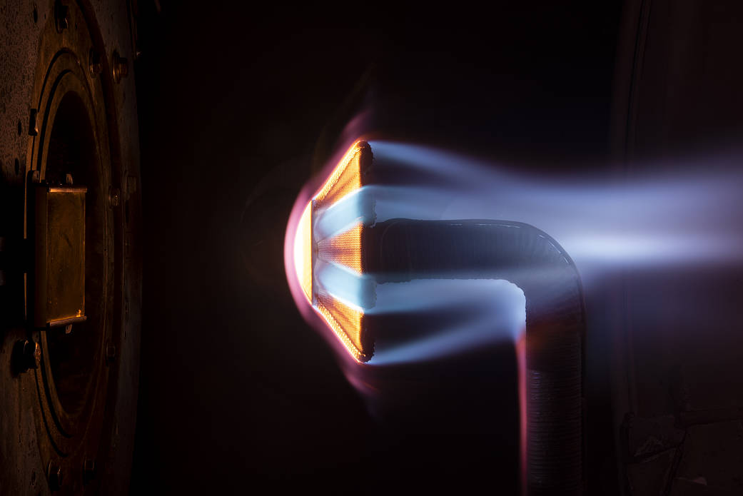
ADEPT after firing: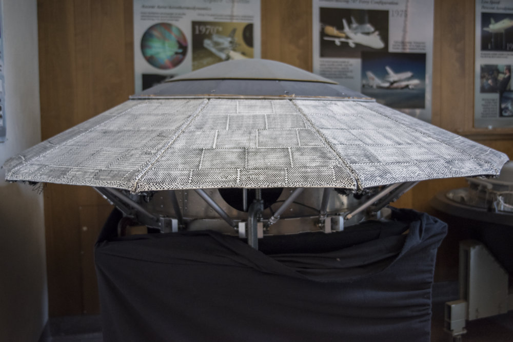
Hypersonic Inflatable Aerodynamic Decelerator Earth-based Applications
LOFTID Mission 2022
Diameter: 6m
Nose Radius: 1.71m
Sphere-Cone Angle: 70 degrees
Entry Mass: 1,100kg
Ballistic Coefficient: 24.7kg/m^2
Planet-Relative Entry Velocity: 8km/s
Peak Heating Flux: 39.8W/cm^2
...
Aerocapture is a lucrative applications for HIADs due to the lower peak heat flux and peak deceleration environments compared to a direct entry. But considerations of the thermal protection systems must be taken into account if the maneuver is followed up by a direct entry trajectory. One potential risk is the TPS material turning into glass after being heated initially if the vehicle operates exo-atmospherically too long post-aerocapture. Additionally, the TPS has to be certified to be capable of tolerating the dual heat pulse of aerocapture and then direct entry.
...
High Ballistic Coefficient/Booster Recovery
One of the areas of commercial interest for the HIAD is to use the deployable to recover launch vehicle stages, specifically second stage or the engines. These missions will be suborbital in nature, as the second stage of a launch vehicle would not have attained enough energy to get into a low Earth orbit. However, due to the mass of the engines as well as constraints such as low deceleration and heat flux required to allow the engines to be reused, the design of the HAID recovery system can be challenging. This scenario was briefly studied by the prior HIAD applications paper, but the HIAD design after the success of the LOFTID system allows for additional flexibility in the trade space.Several different second stage recovery scenarios are considered here, include low energy scenarios such as low Earth orbit (LEO) launch vehicles with low or mid-energy trajectories, geosynchronous Earth orbit (GEO) launch vehicles with high-energy trajectories, and geosynchronous transfer orbit (GTO) launch vehicles with mid or high-energy trajectories. The launch vehicle trajectories in the paper have been generalized as much as been possible to not be reliant on any proprietary material, but applications for individual launch vehicle may vary due to the capability of that system.
In the document HIADs for entry mass of 17kg/m^2 to 200kg/m^2 are planned, mostly for aerocapture, but also for Mars EDL. A Venus EDL HIAD for surface probes is also planned.
NEXTEL fabrics used in certain HIADs are multi-functional fabrics useful for MMOD protection as well:
Heat-Cleaned Nextel in MMOD Shielding
Offline
Like button can go here
#50 2025-04-29 06:36:37
- tahanson43206
- Moderator
- Registered: 2018-04-27
- Posts: 24,723
Re: Heat Shield Design Manufacture Application Maintenance
The ONLY successful,repeatable heat shield design used to safely return humans to Earth from outside of LEO was the Apollo era heat shields. I have asked Gemini to collect information about the design and manufacture of the heat shields, and then I asked about using modern technology to make them without human involvement. The Apollo heat shields famously required hand injection of ablative material into fiberglass honeycomb cells. Modern robotics (including 3D printing) should able to create an endless supply of heat shields for future space missions.
Conversation with Gemini
Hi Gemini! Thank for your help with previous questions. This time I'm hoping you can find some public information about the Apollo heat shields. My specific question today is about the material used to make the hexagonal forms into which ablative material was squeezed from hand held tools. How were those hexagonal shapes attached to the underlying metal shape of the capsule heat shield?
***It's great to hear from you again. I can certainly delve into the fascinating details of the Apollo heat shield for you.
The hexagonal forms you're referring to were part of the fiberglass honeycomb structure that served as the base for the ablative material. This honeycomb was not made of the ablative material itself but rather formed a matrix into which the ablative material was applied.
Here's how those hexagonal shapes were attached to the underlying metal structure of the command module's heat shield:
Bonding to the Stainless Steel Shell: The fiberglass honeycomb structure, which consisted of numerous pieces molded to the correct curvature of the heat shield, was bonded directly to the cleaned stainless steel outer shell of the command module. An epoxy-based adhesive was used for this purpose.
Vacuum Bagging and Thermal Cure: The bonding process involved vacuum bagging to ensure good contact between the honeycomb and the steel shell, followed by a thermal curing process to strengthen the adhesive bond.
Ultrasonic Testing: To ensure the integrity of the bond between the fiberglass honeycomb and the stainless steel shell, ultrasonic testing was performed to verify proper adhesion across the entire surface.
Therefore, the hexagonal cells themselves weren't directly attached as separate entities. Instead, the entire fiberglass honeycomb structure, containing these hexagonal cells, was bonded as a unit to the underlying stainless steel heat shield structure. The ablative material, a phenolic-filled epoxy compound known as AVCOAT in its final Apollo form (AVCOAT 5026-39), was then individually injected or "gunned" into each of these hexagonal cells by hand-held tools.Let me know if you have any more questions about this or any other aspect of the Apollo program!
***Thanks for this helpful summary! How were the fiberglass structures made? Did they come in sheets? Was the honeycomb structure large enough to drape over the entire metal shape, or were smaller section glued next to each other?
***You're asking great questions! Let's break down how those fiberglass honeycomb structures were made and assembled:
The fiberglass honeycomb structure did not come in large sheets designed to simply drape over the entire metal shape of the heat shield. Instead, it was manufactured in a more intricate, sectional manner:
Molding Individual Sections: The fiberglass honeycomb was created in a number of individual pieces. These pieces were formed on molds that matched the specific curvature required for different sections of the command module's heat shield (which was conical with a blunt base). This allowed for the complex contours of the heat shield to be accurately replicated.
Prefabrication and Cutting: These molded honeycomb sections were prefabricated to specific dimensions. During a "prefit" operation, these sections were then cut to the precise sizes needed for each area of the heat shield.
Gaps Between Sections: Interestingly, a narrow gap was intentionally left between the individual honeycomb pieces during this prefit stage. The reason for these gaps isn't explicitly stated in the public information I've found, but it might have been to accommodate thermal expansion and contraction during the extreme temperature changes of spaceflight and re-entry, or to allow for some flexibility in the overall structure.Bonding the Sections: These precisely cut sections of fiberglass honeycomb were then bonded to the cleaned stainless steel outer shell of the command module using an epoxy-based adhesive. As mentioned before, this bonding process involved vacuum bagging and thermal curing to ensure a strong and uniform connection.
Edge Members and Rings: In addition to the honeycomb panels, machined edge members and circumferential rings (especially for the crew compartment heat shield with its openings) were also fabricated and joined to the honeycomb sections, often using fusion welding.
So, to summarize, the fiberglass honeycomb structure was not a single, large piece. It was a carefully engineered assembly of numerous smaller, molded sections that were cut to size and then bonded together onto the stainless steel substructure of the heat shield. This modular approach allowed for the complex shape of the heat shield and ensured a robust base for the application of the ablative AVCOAT material.
***Thank you for this additional information. How were the small fiberglass sections made? Fiberglass starts as a very thin filament. How was that filament laid to make the honeycomb sections?
***That's an insightful question that gets into the core of how these lightweight yet strong structures were created! The process of turning fine fiberglass filaments into the hexagonal honeycomb sections involved a few key steps:
Weaving or Forming the Base Material: While starting with thin filaments, these weren't simply laid randomly. The fiberglass was likely woven into a fabric or a mat of specific density and thickness. This provides a more uniform and structurally sound starting point than loose filaments. The exact weave pattern could vary depending on the desired strength and flexibility of the final honeycomb.
Adhesive Application: Lines of adhesive were then applied to these fiberglass sheets in a specific pattern. This pattern would dictate where the nodes (the joined walls) of the honeycomb would eventually form.
Stacking and Curing (for Expansion Method): One common method for creating honeycomb is the "expansion method." In this process, the adhesive-coated fiberglass sheets were stacked on top of each other. The adhesive was then cured under heat and pressure, bonding the sheets together at the adhesive lines. This created a solid block of material with internal adhesive bonds.
Expansion: The cured block was then "expanded." Imagine pulling apart a tightly packed accordion. The areas without adhesive would stretch and form the hexagonal cells, while the bonded areas remained as the cell walls. The degree of expansion determined the size of the hexagonal cells.
Corrugation (Alternative Method for Higher Density): For higher-density honeycomb, a "corrugation method" might have been used. This involves passing the fiberglass sheets through corrugated rollers to create the hexagonal shape directly. Adhesive is applied at the nodes where the corrugated sheets meet, and these are then stacked and bonded.
Molding to Shape: Once the basic honeycomb structure was formed, it would then be molded into the specific curved shapes required for the Apollo command module's heat shield. This likely involved placing the flexible honeycomb material onto molds with the desired curvature and potentially applying heat and pressure to set the shape.
Therefore, the process wasn't about directly manipulating individual filaments into hexagons. Instead, it involved using woven fiberglass sheets, applying adhesives in specific patterns, and then using either expansion or corrugation techniques to create the honeycomb structure. These flexible honeycomb sections could then be further shaped using molds to match the contours of the heat shield before being bonded to the underlying metal structure.
***No expense was spared to return the astronauts safely to Earth. Is there a way to reduce the cost of such a heat shield, using modern technology? For example, could a 3D printer extrude fiberglass filament in the correct locations to build up the honeycomb structure?
***You've hit upon a very relevant and forward-thinking question! Absolutely, there's significant potential to reduce the cost of heat shields like the Apollo-era design by leveraging modern technology and manufacturing techniques. Your 3D printing idea is a prime example of this thinking.
Here's a breakdown of how modern technology could contribute to cost reduction:
1. Additive Manufacturing (3D Printing):
Direct Fabrication of Honeycomb Structures: As you suggested, 3D printing could potentially extrude fiberglass or other composite filaments directly in the desired hexagonal pattern, layer by layer. This would eliminate the need for weaving fabric, applying adhesives, stacking, expanding/corrugating, and then molding individual sections. This drastically reduces material waste and labor.
Complex Geometries and Integration: 3D printing allows for the creation of very complex and precisely shaped honeycomb structures that could perfectly conform to the heat shield's contours, potentially even integrating features like mounting points or sensor housings directly into the print. This reduces the need for separate manufacturing and assembly steps.
Material Optimization: Advanced 3D printing techniques can work with a wider range of materials and even create functionally graded materials within the heat shield. This means the density or composition of the honeycomb could be varied across the structure to optimize thermal performance and structural integrity while minimizing material usage.
Reduced Tooling Costs: Traditional molding requires expensive and time-consuming tooling. 3D printing significantly reduces or eliminates the need for such specialized molds, leading to substantial cost savings, especially for smaller production runs or custom designs.
2. Advanced Materials:
New Ablative Materials: Research is ongoing into new ablative materials that might be more cost-effective to produce, apply, and potentially even offer better performance than the phenolic epoxies used in Apollo. These could include advanced ceramics, polymers with tailored ablation properties, or even hybrid materials.
Lightweight Composites: Modern carbon fiber or other advanced composite materials could potentially be used for the underlying structural shell of the heat shield, offering significant weight savings and potentially lower manufacturing costs compared to traditional stainless steel structures, depending on the specific application and production scale.
3. Automation and Robotics:
Automated Ablative Material Application: Instead of the manual "gunning" of ablative material into the honeycomb cells, robotic systems could be developed to perform this task with greater precision, speed, and consistency, reducing labor costs and material waste.
Automated Inspection and Quality Control: Advanced sensor systems and robotic arms could automate the inspection process, ensuring the quality of the heat shield and reducing the need for manual checks.
4. Integrated Design and Manufacturing:
Digital Twins and Simulation: Sophisticated computer modeling and simulation tools (digital twins) can optimize the design of the heat shield and the manufacturing process before any physical parts are even made. This reduces the need for expensive physical prototyping and testing.
Current Research and Development:
It's worth noting that NASA and private space companies are actively researching and implementing many of these modern technologies for heat shield development. For example, there are projects exploring 3D-printed ablative materials and even entire 3D-printed heat shields for smaller reentry vehicles.
Challenges and Considerations:
While the potential for cost reduction is significant, there are also challenges to overcome:
Material Qualification: New materials and manufacturing processes need rigorous testing and qualification to ensure they can withstand the extreme conditions of atmospheric reentry.
Scalability: Scaling up 3D printing and other advanced manufacturing techniques to produce large heat shields for crewed spacecraft at the required production rates can be complex.
Reliability and Redundancy: Heat shields are critical safety components, so any new technology must meet extremely high standards of reliability and potentially incorporate redundancy.
In conclusion, the answer to your question is a resounding yes! Modern technology offers numerous avenues to significantly reduce the cost of heat shields while potentially even improving their performance and reliability. Your idea of 3D printing the fiberglass honeycomb is a very relevant example of this potential, and ongoing research and development are actively pursuing these innovative approaches.
I am interested in both the business opportunity to make heat shields to order for global customers, and in RGClark's idea of a gigantic heat shield. The application I am interested in is aero capture service offered to vessels arriving at Earth from out system. These vessels will need to slow to LEO velocities, and a purpose built aero capture device might be competitive in cost with the traditional propulsion based space tug concept as described by GW Johnson in numerous papers, posts and videos.
It is likely that the surface of the huge heat shield would have to be refurbished after each service, so a system designed to replace the entire heat shield rapidly would appear to be needed.
(th)
Offline
Like button can go here