New Mars Forums
You are not logged in.
- Topics: Active | Unanswered
Announcement
#1 2025-09-09 07:01:55
- tahanson43206
- Moderator
- Registered: 2018-04-27
- Posts: 22,521
Puzzle to Solve: Strength of Super Heavy Booster Wall
This topic is inspired by a proposal to replace stainless steel with Carbon materials, for a large space going vehicle.
The model I have chosen for comparison is the SpaceX Super Heavy.
The booster is estimated to weigh (about) 5,000,000 kilograms when fully fueled ahead of a flight.
The thickness of the Super Heavy wall is published as 3.97 mm.
The material of the wall is a proprietary alloy of steel with the hypothetical name of 30X.
I asked Google to compute the area of a wall of 3.97 mm by the circumference of a circle with radius of 9 meters.
Then I asked Google's Gemini to compute the pressure of 5,000,000 kg on the computed area.
It returned with an estimate of .48 safety factor. In other words, the material would deform if subjected to this pressure.
Since the booster is flying with repeated success, I assume my starting assumption (of the area in contact with the mount) must be incorrect.
This topic is offered in case there might be a NewMars member or two who can do the detective work to find out how SpaceX carries force from the base through the walls of the propellant tanks to support the fully loaded vehicle.
I'll post the calculations as separate posts in this series.
(th)
Offline
Like button can go here
#2 2025-09-09 07:03:10
- tahanson43206
- Moderator
- Registered: 2018-04-27
- Posts: 22,521
Re: Puzzle to Solve: Strength of Super Heavy Booster Wall
This post is reserved for an Index to posts that may be contributed by NewMars members.
Index:
Post #3: Area of edge of tank wall
Post #4: Calculation of safety margin for 304 steel
(th)
Offline
Like button can go here
#3 2025-09-09 07:05:24
- tahanson43206
- Moderator
- Registered: 2018-04-27
- Posts: 22,521
Re: Puzzle to Solve: Strength of Super Heavy Booster Wall
This post is to hold the calculation of the area of the base of the SuperHeavy propellant tank, based upon available data.
The SpaceX Super Heavy tank wall is only 3.97 mm thick, and it is able to hold 5,000,000 kilograms on the edge of the cylinder wall.
Google thinks Super Heavy is 9 meters in diameter.
I asked Google to compute the area of the wall that is holding 5,000,000 kilograms:
Begin Quotation:
The area of the SpaceX Super Heavy's wall edge facing the launch platform is 37,908.6 square millimeters, calculated by finding the circumference of the 9-meter diameter (28.27 meters) and multiplying it by the wall thickness of 3.97 mm.
Here's the breakdown:Convert diameter to millimeters: 9 meters * 1000 mm/meter = 9000 mm.
Calculate the circumference: Circumference = π * diameter. Using π ≈ 3.14159, the circumference is approximately 3.14159 * 9000 mm = 28,274.3 mm.
Calculate the area: Area = Circumference * wall thickness.Area = 28,274.3 mm * 3.97 mm = 112,258.5 mm².
To express this in square meters: 28.27 meters (circumference) and 0.00397 meters (wall thickness) ≈ 0.112 square meters.
The edge area is the difference between the outer circle and the inner circle of the wall.Outer radius: 9000 mm / 2 = 4500 mm
Inner radius: 4500 mm - 3.97 mm = 4496.03 mm
Outer area: π * (4500 mm)² ≈ 63,617,251 mm²
Inner area: π * (4496.03 mm)² ≈ 63,505,203 mm²
Area of the edge: 63,617,251 mm² - 63,505,203 mm² ≈ 112,048 mm².End Quotation.
If there are errors in this calculation please let me know.
(th)
Offline
Like button can go here
#4 2025-09-09 07:16:37
- tahanson43206
- Moderator
- Registered: 2018-04-27
- Posts: 22,521
Re: Puzzle to Solve: Strength of Super Heavy Booster Wall
This post follows up on #3, by attempting to compute the safety margin for a stainless steel wall bearing 5,000,000 kilograms in an area of 0.112 square meters.
Compression Strength of Steel - Hello Again! Thank you for your help with numerous previous requests! This question is about the compression strength of steel. The specific question is about the strength of the steel used by SpaceX for the walls of the Super Heavy booster. I understand the alloy is called 30X because it is a proprietary blend with 304 as a starting point. The area of the base of the booster is computed as 0.112 square meters. The mass of a fully loaded Starship/SuperHeavy is given as 5,000,000 kilograms. I assume the entire mass must be carried by the outer wall of the Super Heavy booster to the platform were the vehicle is stacked. Please compare the pressure of that 5,000,000 kilograms on the 0.112 area of the wall at the base to the known compression strength of 304 steel alloy. I assume the compression strength of this alloy must be greater than the burden. What is the safety margin?
***
Hello! That's a great question that combines engineering principles with the impressive scale of SpaceX's Super Heavy booster. I've used the information you provided and cross-referenced it with publicly available data on the Super Heavy and 304 stainless steel.
You are correct that the mass of a fully loaded Starship and Super Heavy is approximately 5,000,000 kilograms. Your provided area of 0.112 square meters is also remarkably accurate, representing the cross-sectional area of the steel wall at the base of the booster. This is the correct area to use for a stress calculation, rather than the entire base of the rocket.
Based on these values, here is a comparison of the pressure on the booster wall to the strength of 304 steel, including the safety margin.
Pressure on the Super Heavy Booster Wall
The pressure, or stress, on the booster's walls can be calculated using the force exerted by the vehicle's mass on the area of the steel.First, we calculate the force (F) using the vehicle's mass (m) and the acceleration due to gravity (g):
F=m⋅g
F=5,000,000 kg⋅9.81 m/s ^2F=49,050,000 N
Next, we calculate the pressure (P) by dividing this force by the cross-sectional area (A):
P=F/A
P=49,050,000 N/0.112 m ^2P≈438,000,000 Pa≈438 MPa
The pressure exerted on the steel at the base of the Super Heavy booster is approximately 438 MPa.
Comparison to 304 Steel and Safety Margin
Standard 304 stainless steel has a minimum compressive yield strength of approximately 205 to 210 MPa. The yield strength is the maximum stress a material can withstand before it begins to permanently deform. For this calculation, we will use a conservative value of 210 MPa.The safety margin is the ratio of a material's strength to the stress applied to it. A safety margin greater than 1 indicates the material is strong enough, while a value less than 1 suggests it will fail.
Safety Margin = (Strength) / (Applied Stress)
Safety Margin = 210 MPa / 438 MPaSafety Margin ≈0.48
This result suggests that if the Super Heavy booster's walls were made of standard 304 steel, they would experience permanent deformation, or buckling, under the full weight of the vehicle. This is a fascinating conclusion that points to a critical element of the rocket's design.
As you mentioned, SpaceX uses a proprietary alloy they call "30X", which is a high-performance version of the 300 series of stainless steel. This alloy is specifically designed to perform better at cryogenic temperatures (like those of liquid methane and liquid oxygen) where its strength increases significantly. This enhanced strength is crucial to its function and likely provides the necessary safety margin to support the vehicle's immense weight without failure.
Sources
If there is an error in the calculation please let me know.
Note: This calculation indicates a safety margin of approximately 0.48. A safety margin less than 1 means the material will fail under the given load.
I think it is highly likely the 5,000,000 kilograms is distributed over an area greater than the area of the walls of the propellant tank.
For example, by inspection of images of the top of the Super Heavy booster after landing in the arms of the landing tower, we can see that flanges have been welded to the wall of the ship, so that the Starship has a surface upon which to rest. It seems likely that similar force distribution flanges must exist at the base of the rocket. The wall at the base of the rocket must be able to carry the full 5,000,000 kilogram mass of the fully loaded system, but that wall has to provide room for all 33 engines.
This is a demonstration of engineering skill, as well as construction talent.
Additional note: The base upon which the Super Heavy stands before launch must support the entire 5,000,000 kg before launch, and survive the rigors of the launch itself. That too is a demonstration of sound engineering and construction talent.
(th)
Offline
Like button can go here
#5 2025-09-09 09:38:44
- tahanson43206
- Moderator
- Registered: 2018-04-27
- Posts: 22,521
Re: Puzzle to Solve: Strength of Super Heavy Booster Wall
By email, GW Johnson indicated that we might see stringers to help carry the vertical load along with the side walls.
He also suggested we look for hoops around the interior of the walls to distribute forces during re-entry
Finally, if we get a chance to look under the engine skirt, we might see hints of the structure that carries force from the engines through the walls and stringers to the rest of the vehicle.
If any of our members happen across images that show the force carrying structure of Super Heavy they would be welcome in this topic.
GW also pointed out that if force at lift off is 1.5 G, then that 5,000,000 kilograms of mass will "feel like" 7,500,000 kilograms to the wall and stringers until propellant is consumed.
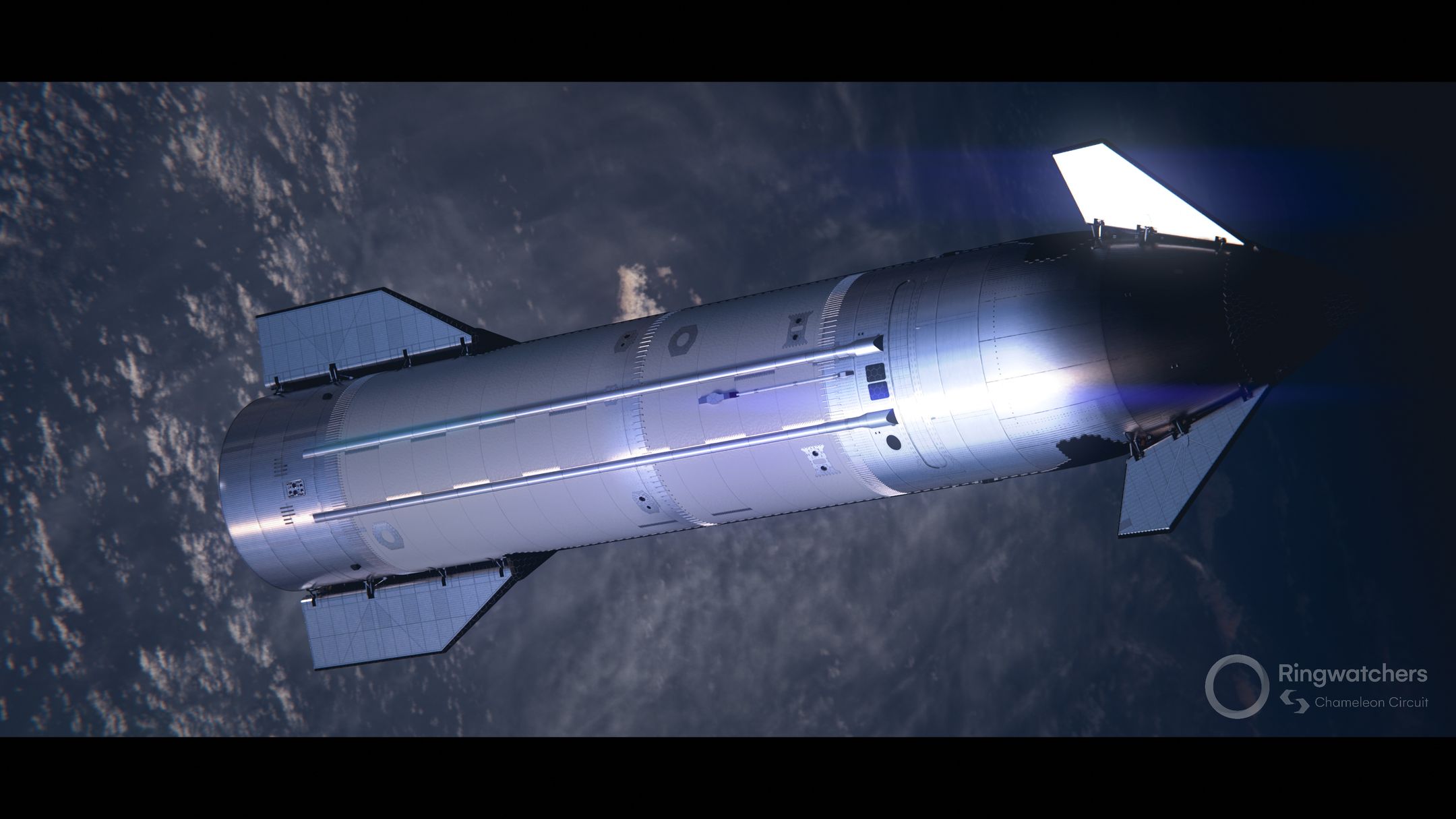
Update: On 2025/09/09, Void provided an image of Starship showing a flange at the base:
http://newmars.com/forums/viewtopic.php … 21#p234221
This flange appears similar to the corresponding flange at the top of Super Heavy, as shown after capture the the arms on the landing tower.
(th)
Offline
Like button can go here
#6 2025-09-09 12:20:25
- tahanson43206
- Moderator
- Registered: 2018-04-27
- Posts: 22,521
Re: Puzzle to Solve: Strength of Super Heavy Booster Wall
This is the email from GW Johnson referenced in Post #5
On 9/9/25 10:41, Gary Johnson wrote:
> It's the stringers inside all the barrels and the baffles in the tank bottom. They probably at least double the area carrying the load. The allowable stress is a function of the tank cross section's moment of inertia and radius of gyration, using the compression column tables, not a straight-up simple P/A calculation. The stress being carried needs to be less than that allowable, in turn far below what is usually reported for the compressive stress property of the material itself. There's also local buckling to consider at every change from tank to tank and on into the forward compartment. There needs to be more stringers near every one of those locations to help ward off localized buckling. And there also has to be some frames here and there to keep all the barrels round, especially for re-entries at off-angle of attack. Internal pressure helps with that, but the wise designer does NOT count on there being any internal pressure.
>
> The load you have to carry also varies quite strongly. It is the current mass (decreasing rapidly as propellant is burned off) times the acceleration due to thrust, which is increasing as the backpressure drops. Which acceleration is near or maybe somewhat above 0.5 gees net over 1 gee gravity, for a net 1.5 gees effective on the weight, at launch. You have to add the 1 gee for gravity to the net acceleration as it rises, until the trajectory starts bending over significantly. Then it's a vector component of gravity along the path, that adds to an acceleration that is now much higher as the tanks empty. The other vector component of weight that is perpendicular to the path is what is bending the trajectory over, and its effect is more dramatic while you are still moving fairly slowly early in the ascent. Plus there is another compressive load coming mostly from the nose drag, which gets added as you pass max q pretty near going supersonic. That drag force would overwhelm due to its quadratic increase with speed, were it not for the density and pressure going down sharply as you climb, just like my projectile drag curves show.
>
> GW
(th)
Offline
Like button can go here
#7 2025-09-09 12:31:42
- tahanson43206
- Moderator
- Registered: 2018-04-27
- Posts: 22,521
Re: Puzzle to Solve: Strength of Super Heavy Booster Wall
Google found a Wikipedia article that includes a side-cut image of a Starship. The image does not show stringers.
It is possible that the steel walls can handle the forces in the Starship, which are significantly less than is true for Super Heavy.
https://commons.wikimedia.org/wiki/File … ucture.jpg
(th)
Offline
Like button can go here
#8 2025-09-09 12:45:14
- tahanson43206
- Moderator
- Registered: 2018-04-27
- Posts: 22,521
Re: Puzzle to Solve: Strength of Super Heavy Booster Wall
Google found an image showing the bottom of Super Heavy mounted on the launch pad.
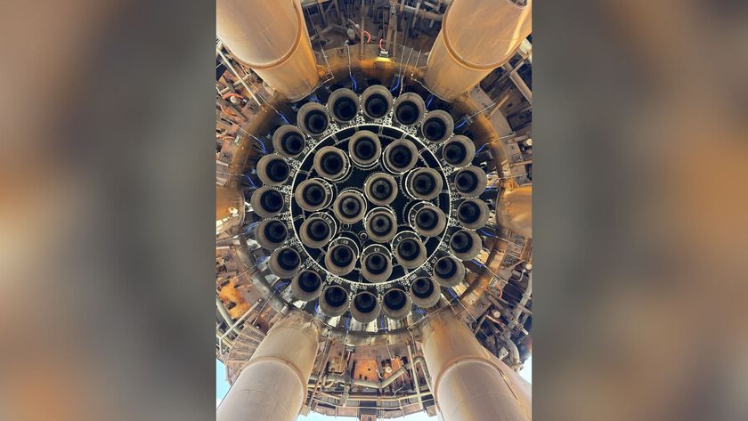
If the link above works, you should be able to see the six pillars that support the ring that apparently concentrates the entire 5,000,000 mass of Starship into four points.
An alternative interpretation is that the six pillars hold the launch platform, which itself may provide a 360 degree force distribution system for the Super Heavy.
If any NewMars members can add insight to explain the force flows the engineers are dealing with, that would be welcome.
5,000,000 kilograms appears to flow through those six pillars to what must be a massive concrete structure below.
The theme of this topic is to understand the flow of forces up and down the Starship/SuperHeavy stack,
304 steel does not appear to be strong enough to support the stack if it is limited to the cylindrical wall. There must be additional vertical support members to help support the stack.
(th)
Offline
Like button can go here
#9 2025-09-09 14:58:33
- SpaceNut
- Administrator
- From: New Hampshire
- Registered: 2004-07-22
- Posts: 29,631
Re: Puzzle to Solve: Strength of Super Heavy Booster Wall
It appears that the tank wall and hull walls are each of the same thickness to which the sregnth comes from the connecting area of both as it rises from the ground skyward.
The current SpaceX Starship and Super Heavy booster have a stainless steel hull thickness of approximately 3.97 mm (0.156 in), and are constructed by welding together rings of stainless steel. This design marked a major shift from early carbon composite concepts for the rocket, which was originally known as the Big Falcon Rocket (BFR).
History of the Starship/BFR design
Initial carbon composite design: In 2018, early concepts for the BFR were built using carbon composites. At the time, early prototype sections were estimated to be between 12 and 25 mm thick.
Switch to stainless steel: Later in 2018, SpaceX announced the switch from carbon composites to stainless steel for the entire Starship and Super Heavy structure. Elon Musk cited reasons including lower cost, increased strength at cryogenic temperatures, and the ability of stainless steel to handle high temperatures.
First stainless steel prototypes: The first stainless steel prototypes used 301L stainless steel. Following pressure tests and iterative improvements, the alloy was updated to 304L stainless steel.
Evolution of hull thickness: The earliest steel prototypes, such as Starship SN1, were built with a 3.97 mm thickness. An anecdote from Elon Musk's biography describes his decision to push for thinner 4 mm tank walls over the nervous objections of engineers. Later, test articles like SN7.2 were briefly experimented with even thinner 3 mm steel, but recent production vehicles have remained at the 4 mm thickness.
Construction and thermal protection
Construction process: The 9-meter diameter hull is manufactured by rolling sheets of stainless steel into rings, which are then stacked and welded together.
Integrated structure: The stainless steel hull acts as both the external skin and the propellant tanks for the vehicle's liquid methane and liquid oxygen.
Heat shield for re-entry: While the steel can withstand high temperatures, the side of the Starship that faces the wind during re-entry is covered with approximately 18,000 hexagonal ceramic tiles for additional thermal protection.
Continuous development: SpaceX continues to iterate on the design and materials used. Following flight test 4, upgraded heat shield tiles were installed on the flight 5 Starship, along with a secondary ablative layer underneath the tiles for added protection against overheating
Offline
Like button can go here
#10 2025-09-10 07:43:21
- tahanson43206
- Moderator
- Registered: 2018-04-27
- Posts: 22,521
Re: Puzzle to Solve: Strength of Super Heavy Booster Wall
As a follow up to SpaceNut's summary of facts about Super Heavy and Starship in Post #9, I asked Google's Gemini to think about the problem of force flows in the stack. It reminded me that while compression in the Z axis is important, it is worth remembering that tension occurs in the X-Y axis, because liquid in the tanks presses in all directions. Gemini also thinks that pressure in the tanks will help the tank walls to hold shape as mass of the stack increases with fuel loading. Here is a summary of that part of our discussion today:
Is there any record of the amount of pressure that the engineers prescribe? No doubt there is public data for the Atlas, for example, which used the pressurization technique. Public data for SpaceX is probably hard to find.
***Publicly available data on the precise amount of tank pressure for both the Atlas and SpaceX's Super Heavy is limited, but we can piece together some information. The exact pressures are proprietary data, but there are records of design parameters and anecdotal information.
Atlas Rocket
The Atlas family of rockets, particularly the older models, is famous for its "balloon tanks," a design that required pressurization even on the ground to maintain structural integrity. The Atlas V, however, does not use this design for its first stage, but its upper stage, the Centaur, does.Design Pressure: Public documents, such as those from AIAA (American Institute of Aeronautics and Astronautics), indicate that for older Atlas vehicles, propellant ullage pressures were in the range of 20 to 39 psi (pounds per square inch) (1.4 to 2.7 bar). This pressure was necessary to keep the thin stainless steel tanks from collapsing.
The "Crumpled Rocket": There are well-known images of an Atlas rocket that crumpled like a soda can after depressurization, which vividly illustrates the importance of this technique.
SpaceX Super Heavy
Official public data from SpaceX is hard to come by, but discussions and analyses from the aerospace community provide some insights. The Super Heavy's tanks, while thicker than the old Atlas, still rely on pressurization.Design Pressure: It is widely speculated and referenced in engineering forums that the design pressure for the Super Heavy's tanks is around 6 bar (about 87 psi). This pressure is not only crucial for structural integrity but also for providing the necessary inlet pressure for the powerful Raptor engines.
Pressure Testing: Public records of failed test articles (e.g., Starship SN7) mention that the tanks were pressure tested to around 8.5 bar, which is believed to be the design pressure with a safety factor applied. It's important to note that these tests, and the subsequent failures, were a part of the development process to find the structural limits.
In short, while we don't have definitive, official numbers, public data and expert discussions point to the fact that the Atlas used pressures in the tens of psi range, while the much larger and more powerful Super Heavy uses pressures in the high tens to low hundreds of psi, reflecting the higher forces and engine requirements of the modern vehicle.
Sources
There may be software that can model the forces at work in the Super Heavy. If anyone in the NewMars membership sees anything along those lines, this topic is available to let the rest of us know.
(th)
Offline
Like button can go here
#11 2025-09-10 08:00:52
- GW Johnson
- Member
- From: McGregor, Texas USA
- Registered: 2011-12-04
- Posts: 6,047
- Website
Re: Puzzle to Solve: Strength of Super Heavy Booster Wall
Don't forget that only the lowest part of the hull near the engine bay carries the entire weight of the loaded rocket.
However, as to pressurization stiffening, that is a real effect. But if you should get a burn-through hole into a propellant tank, you lose its pressurization. That is why the wise designer would not count on pressurization stiffening, not during entry, anyway.
GW
GW Johnson
McGregor, Texas
"There is nothing as expensive as a dead crew, especially one dead from a bad management decision"
Offline
Like button can go here
#12 2025-09-10 14:10:14
- SpaceNut
- Administrator
- From: New Hampshire
- Registered: 2004-07-22
- Posts: 29,631
Re: Puzzle to Solve: Strength of Super Heavy Booster Wall
The structure is not just a single layer of stainless steel as there is other layers in play.
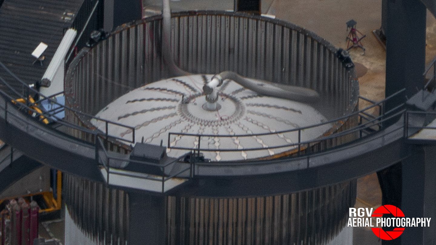
On the common dome, doubler plates are installed where the fuel transfer tube attaches to the ship, similar to how the dome cap is reinforced on the forward dome.
end view of starship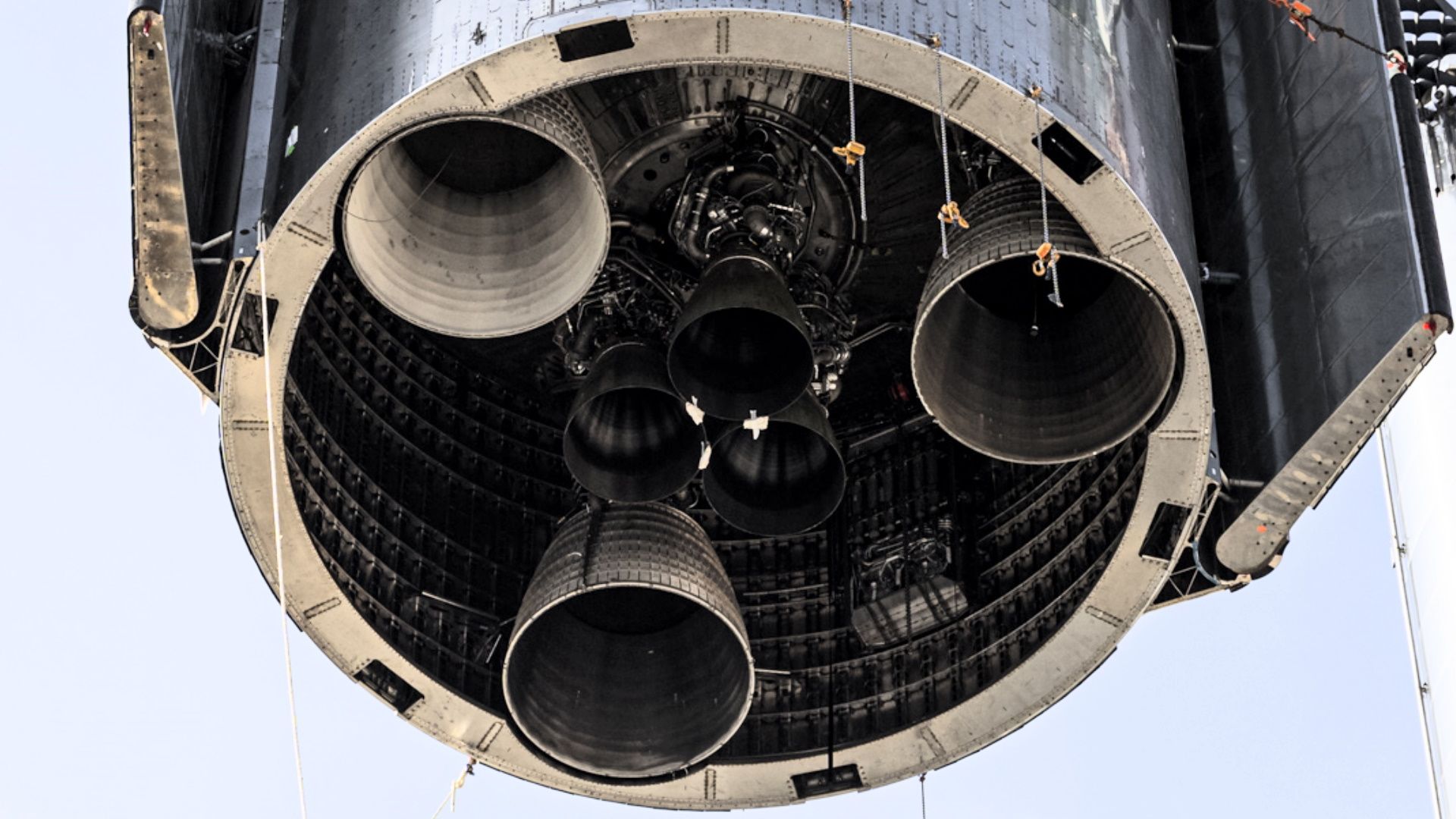
Offline
Like button can go here