New Mars Forums
You are not logged in.
- Topics: Active | Unanswered
Announcement
#2051 2025-04-13 11:05:24
- GW Johnson
- Member
- From: McGregor, Texas USA
- Registered: 2011-12-04
- Posts: 6,072
- Website
Re: Starship is Go...
RE: post 2049 just above.
The image number labels are at the tops of the images. They are out of order in the posting.
The one labeled “image 8” was intended to be the first one, showing exactly what and how I was trying to do in the study. What I varied, how I varied it, and more importantly, what did not vary. I kept the heat shield nose radius ratioed to its diameter constant, as that nose radius is a major influence on the heating. Larger is lower heating. Had it not increased, the heating results would have been very much higher.
There were 4 images that were entry trajectory analysis results illustrations, to show where the numbers came from. The one labeled “image 5” was the first, with heat shield diameter 4 m equal to the 4 m base diameter of the protected object. This corresponds to a ballistic coefficient of 300 kg/sq.m, comparable to the Apollo command module’s 313.
The one labeled “image 3” was intended to be next, showing an 8 m dia heat shield on that same 4 m dia object, for a ballistic coefficient of 75 kg/sq.m.
I doubled the heat shield dia again to 16 m, for that same 4 m dia object, in the image labeled “image 6”. That produced a ballistic coefficient of 18.75 kg/sq.m.
I doubled the heat shield diameter yet again to 32 m for the same 4 m dia object, for a ballistic coefficient of only 4.68+ kg/sq.m. That one is labeled as “image 1”.
These 4 analyses produced peak convective heating rates at stagnation, and peak plasma radiation heating rates at stagnation, that were relatively trivial. I summed these to a total heating rate at stagnation, and computed the stagnation point surface temperatures for which thermal re-radiation equaled the combined convective-radiation input, without ablation, without conduction into the interior, and without any other cooling at all. Those results are summarized in plot form in the image labeled “image 2”. The temperatures decrease but stay rather high until the ballistic coefficient falls below about 50 kg./sq.m.
I also used the peak deceleration gees to estimate the peak average pressure exerted across the heat shield. Those results are also plotted in “image 2”. I was surprised to see the peak deceleration gee being the same for all cases. I expected higher gee with more heat shield area. But the thinner air higher up apparently just offsets that effect.
I went back and updated these results by estimating temperatures away from the stagnation point with the results plotted in “image 4”. The stagnation point plot is there, plus a plot representing attached flow on the windward side of the heat shield near its rim, and another plot representing any of the leeward heat shield surfaces, or the lateral surfaces of the protected object. All of these are surfaces within the separated wake zone.
Looking at those results in “image 4”, at ballistic coefficient near 50 kg/sq.m, the stagnation point temperature is at least 1000 C. Higher if reflective. Near the rim of the heat shield, that is still at least 800 C, higher if reflective. Only for the separated wake zone surfaces is it 500 C, yet higher if reflective. There are lower temperatures shown in the plots at lower ballistic coefficients, but the structures may well be getting too fragile to fly, despite the lower average pressure below the 4 KPa at 50 kg/sq.m.
I put together a little table of max service temperatures for several materials, which got posted as “image 7”. It’s not in any way comprehensive. With a rim temperature of 800 C or higher, there is simply no way in hell that any sort of silicone elastomer on any sort of fabric material, is going to be in reusable shape after a single entry from low Earth orbit! That is the real takeaway here!
There is a very good reason that practical spacecraft heat shields have all been ablatives up to now, the only exceptions being the refractory ceramics on the Space Shuttle and the X-37B. I think I just showed you exactly why that has been true. By doing the same kind of things H. Julian Allen and A. J. Eggers were doing for warhead entry scenarios, back in the early 1950’s. The physics has not changed. Some of the materials have.
GW
Last edited by GW Johnson (2025-04-13 11:08:51)
GW Johnson
McGregor, Texas
"There is nothing as expensive as a dead crew, especially one dead from a bad management decision"
Offline
Like button can go here
#2052 2025-04-14 11:29:56
Re: Starship is Go...
Thanks for that, GW. Your updated version of Fig 6. is closer to the Dr. Akin result of approx. stagnation temperature 800°C for a ballistic coefficient of ca. 20 kg/sq.m:

Your updated Fig 6:

This is in the range of the max. service temperature for some steel alloys:

Bob Clark
Last edited by RGClark (2025-04-14 11:32:35)
Old Space rule of acquisition (with a nod to Star Trek - the Next Generation):
“Anything worth doing is worth doing for a billion dollars.”
Offline
Like button can go here
#2053 2025-04-14 12:19:20
- kbd512
- Administrator
- Registered: 2015-01-02
- Posts: 8,306
Re: Starship is Go...
I'd like to point out how ridiculously low 18.75kg/m^2 (3.84lbs/ft^2) truly is. That is the wing loading equivalent of the average ultra-light aircraft, none of which are made from materials that will withstand 800C. For a 150,000kg dry mass vehicle, the heat shield surface area is 8,000m^2. A regulation American football field is 57,600ft^2, or 5,351m^2, which means the heat shield would need to be 1.5X the size of a football field. For all practical purposes, we don't build any flying vehicles of that size.
The Nextel fabric that ADEPT was made from costs around $20/ft^2. It would survive 850C without issue. However, the fabric for this heat shield would cost more than all 6 Raptor engines (now less than $200K per copy), and I'm guessing that this deployable fabric heat shield would need to be jettisoned to allow Starship to land. How do we do that?
This seems like a highly impractical solution without some kind of radical redesign of Starship. Starship might be able to deploy such an enormous heat shield, and it should protect Starship from reentry heating without any real issue, but how does one then land a vehicle ensconced in this giant fabric "lifting body surf board"?
Starship on a football field:
Where the heck are we stowing a heat shield that large and how are we either getting rid of it to land vertically, or somehow using the heat shield to soft land on the ocean?
Offline
Like button can go here
#2054 2025-04-14 14:22:10
- GW Johnson
- Member
- From: McGregor, Texas USA
- Registered: 2011-12-04
- Posts: 6,072
- Website
Re: Starship is Go...
Bob:
The final results are excruciatingly-sensitive to the speed and angle at entry interface, something I did not vary in this study. Just a tad faster or steeper raises gees and peak heating. Just a tad slower or shallower lowers peak gees and peak heating.
Dig out the entry spreadsheet posted in the "interplanetary transportation" topic, "orbit mechanics class traditional" thread., and run it for yourself. It has a user's manual. Just be sure to use realistic inputs. It's a "garbage-in, garbage-out" thing.
Kbd512:
Nextel now makes several ceramic cloths, all pretty much intended for aircraft engine nacelle fire curtain application. I am very familiar with the oldest one, an AF-19 fabric made from Nextel-312 fibers, which are aluminosilicate minerals. All these have a solid phase change at about 2300 F, leading to ~3% volume shrinkage, and catastrophic embrittlement. Which upon cooldown renders them extremely fragile, crumbling away to dust at the touch of the slightest breath of air. Those minerals melt at about 3300 F, but you cannot reuse those cloths (or anything else you make from them) if you exceed about 2200-2300 F.
GW
GW Johnson
McGregor, Texas
"There is nothing as expensive as a dead crew, especially one dead from a bad management decision"
Offline
Like button can go here
#2055 2025-04-14 14:45:55
- kbd512
- Administrator
- Registered: 2015-01-02
- Posts: 8,306
Re: Starship is Go...
GW,
My underlying point is that SpaceX requires RCC to make their fully exposed body fins and hinge lines survive reentry heating. We're not going to achieve ultra-light-like wing loading for a super heavy lift launch vehicle because it's not practical. We have our "go-to" materials for surviving reentry heating and they happen to work.
Offline
Like button can go here
#2056 2025-04-14 16:49:16
- GW Johnson
- Member
- From: McGregor, Texas USA
- Registered: 2011-12-04
- Posts: 6,072
- Website
Re: Starship is Go...
Actually, I quite agree with you.
GW
GW Johnson
McGregor, Texas
"There is nothing as expensive as a dead crew, especially one dead from a bad management decision"
Offline
Like button can go here
#2057 2025-04-14 17:22:14
- tahanson43206
- Moderator
- Registered: 2018-04-27
- Posts: 22,881
Re: Starship is Go...
For RGClark...
Here is an image GW asked me to post for you:

(th)
Offline
Like button can go here
#2058 2025-04-15 08:03:21
Re: Starship is Go...
I'd like to point out how ridiculously low 18.75kg/m^2 (3.84lbs/ft^2) truly is. That is the wing loading equivalent of the average ultra-light aircraft, none of which are made from materials that will withstand 800C. For a 150,000kg dry mass vehicle, the heat shield surface area is 8,000m^2. A regulation American football field is 57,600ft^2, or 5,351m^2, which means the heat shield would need to be 1.5X the size of a football field. For all practical purposes, we don't build any flying vehicles of that size.
…
I discussed before I think SpaceX is not taking the best approach to developing the Superheavy/Starship. They were spectacularly successful with the Falcon 9 by first getting the expendable version, then proceeding to reusability. If they had taken that approach with the SH/SS they would already be flying the expendable version and perhaps even also the partially reusable one, i.e., reusing the booster only, a la the Falcon 9.
Note then for the expendable version the dry mass of the Starship might have been as low as 40 tons:
Elon Musk @ElonMusk
Probably no fairing either & just 3 Raptor Vacuum engines. Mass ratio of ~30 (1200 tons full, 40 tons empty) with Isp of 380. Then drop a few dozen modified Starlink satellites from empty engine bays with ~1600 Isp, MR 2. Spread out, see what’s there. Not impossible.
https://x.com/elonmusk/status/1111798912141017089?s=61
Then with the ca. 20 ton fairing, the needed ‘wing’ area need to be added might be ca. 1,800 sq.m. But this wouldn’t be as heavy as regular wings with their thickness to generate aerodynamic lift. It would only have the character of a thin plate since it is meant only to be a drag decelerator.
Bob Clark
Last edited by RGClark (2025-04-15 08:53:00)
Old Space rule of acquisition (with a nod to Star Trek - the Next Generation):
“Anything worth doing is worth doing for a billion dollars.”
Offline
Like button can go here
#2059 2025-04-15 09:40:41
Re: Starship is Go...
I discussed in the blog post the inflatable conical shield being investigated to allow the Cygnus cargo capsule to be reusable had the same ballistic coefficient as the Starship of ca. 60 kg/sq.m IF you take the dry mass of the Starship at the expendable 40 tons.
The problem is this conical shield was sized for a returning craft of mass of ca. 5 tons and it’s not certain how the conical shield would scale to higher mass, such as the Starship.
But there might be an example that would give us a reusable thermal shield for a vehicle the size of Starship. I’m thinking of the X-33/Venturestar.
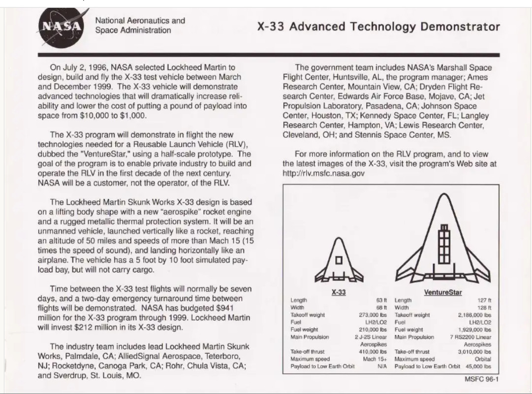
The length in meters was 38.7m and width 39m. For the dry mass, the total gross weight was 2,186,000 lbs, propellant weight 1,929,000 lbs, and payload weight 45,000 lbs; giving a dry weight of 212,000 lbs, or 96,400 kg.
Using a hypersonic drag coefficient of 2, and considering the triangular planform requires multiplying by 1/2 the length*width to get the area, the ballistic coefficient calculates out to be 96,400/(2*1/2*38.7*39) = 64 kg/sq.m.
Remarkably close to the ballistic coefficient of the Starship at the 60,000 kg mass of the expendable’s dry mass + fairing mass.
But the added weight of the metallic shingle TPS of the X-33/Venturestar can’t be too high to allow the ballistic coefficient to remain close to this value.
The areal density of the metallic shingle TPS was about 10 kg/sq.m:
REUSABLE METALLIC THERMAL PROTECTION SYSTEMS DEVELOPMENT
Max L. Blosser*, Carl J. Martin*, Kamran Daryabeigi*, Carl C. Poteet **
*NASA Langley Research Center, Hampton, VA, USA
** JIAFS, The George Washington University, Hampton, VA, USA
https://ntrs.nasa.gov/api/citations/200 … 095922.pdf
The metallic tiles had better resistance to impact and rain than the ceramics at about the same weight.

Fig.3 Layered metallic sheeting separated by insulation.

Fig.21 Metallic TPS at same weight of ceramic tiles, ~10kg/sq.m.
At a 10 kg/sq.m. areal density, the added weight covering just the lower half of the Starship would be (1/2)*Pi*9*50*(10 kg/sq.m.) = 7,060 kg, proportionally small enough that the ballistic coefficient would still be ca. 60 kg/sq.m.
This would be advantageous in that you don’t need added wings and you don’t need an additional conical shield.
BUT for this to work SpaceX would have to go back to the smaller, expendable mass of the Starship. SpaceX had tested the X-33 metallic shingles and concluded they were inadequate. But that was with temperatures developed with the higher 150+ ton Starship. With a lighter dry mass, much reduced temperatures result.
Bob Clark
Last edited by RGClark (2025-04-15 09:46:40)
Old Space rule of acquisition (with a nod to Star Trek - the Next Generation):
“Anything worth doing is worth doing for a billion dollars.”
Offline
Like button can go here
#2060 2025-04-16 09:44:37
Re: Starship is Go...
Thanks for that, GW. I wanted to ask in regards to the “hot metal” TPS, the heat would rapidly propagate to the upper side of the vehicle. This means the radiative surface area would double, thus doubling the heat emission.
Shouldn’t this improve the survivability?
Bob Clark
Old Space rule of acquisition (with a nod to Star Trek - the Next Generation):
“Anything worth doing is worth doing for a billion dollars.”
Offline
Like button can go here
#2061 2025-04-20 09:53:27
- GW Johnson
- Member
- From: McGregor, Texas USA
- Registered: 2011-12-04
- Posts: 6,072
- Website
Re: Starship is Go...
That link in the quote in post 2060 just above does not take me to anything I ever sketched. It takes me to the imgur webpage, not to any particular image.
Meanwhile, just to let everybody know, SpaceX has been testing a lot of Raptor engines lately, quite a few up on the tower stand where they are quite loud. There's about a 10-Hertz inaudible pressure wave from these tests that really rattles the windows and doors and chandelier-type light fixtures. I feel it with Raptors, but not Merlins. I suspect the soot cloud in the flame with kerosene has an oscillation damping effect that is missing with the methane.
That too-low-to-hear but significant amplitude signal suggests a nontrivial thrust oscillation with a fairly-well-defined 10 Hertz frequency in the Raptor that the Merlins just do not have. If there are any vehicle or plumbing modes near that 10-Hertz frequency, resonance could easily cause POGO problems.
Those tests have been running pretty close to 6-7 minutes each, essentially a full duration ascent burn for either stage. I cannot tell a vacuum Raptor from a sea level Raptor, they all sound about the same, from 6 miles away. I suspect the vacuum tests are running with something approximating a normal shock, essentially just barely aft of the exit plane. They would have to be at near full pressure, and would be separated between ignition at some reduced pressure, and throttle-up to test conditions. I usually don't hear the "explosions" that were full-power starts. Von Braun found reduced-throttle ignition to be far more survivable, about 80 years ago.
As for Bob's question, the object in the wake zone behind an extended heat shield sees an exposure to exactly the same gas/plasma effective temperature as exists at the stagnation point, of value in degrees K numerically equal to flight speed in m/s, to about 10% accuracy. At 8 km/s you are looking at about 8000 K effective plasma temperature. At 4 km/s, 4000 K. Etc.
This high effective temperature persists well into the flow alongside the wake zone. The gas in the wake zone is still at that same temperature, just not moving very fast at all relative to the surface. The convective heating rates in the wake are much lower than stagnation, because there is less or almost no fluid scrubbing effects, and the pressure (density) is nil. A crude estimate is stagnation convection/10. The plasma radiation heating rates are also lower, because the radiating plasma shock layer is more distant from the surfaces at risk, yet it still "shines" on everything. A crude estimate in the separated wake zone would stagnation radiation heating/2.
On the windward side of your extended heat shield, there is attached flow at significant pressure (density) all the way out to the rim, and the radiating shocked plasma layer is very close to all of the windward surface. Crude estimates near the rim might be stagnation convection/3, and the same radiation heating rate as the stagnation radiation heating rate, just all over the heat shield, right out to the rim.
The "nose radius" of the heat shield affects the stagnation heating values, but in opposite ways for convection and radiation. Sharper nose radius rapidly increases convective stagnation heating. Flatter nose radii greatly increase stagnation plasma radiation heating. Exactly how those balance out is both atmosphere model-dependent, and entry trajectory details-dependent.
The net result is quite different at Mars than Earth. Earth heat shields do better as more-or-less spherical segments with large "nose" radii. Mars heat shields do better as conical shapes with slightly-blunted tips. It's not one-size-fits-all, not by a long shot! Every situation is different!
GW
Last edited by GW Johnson (2025-04-20 10:24:46)
GW Johnson
McGregor, Texas
"There is nothing as expensive as a dead crew, especially one dead from a bad management decision"
Offline
Like button can go here
#2062 2025-04-20 12:15:00
- tahanson43206
- Moderator
- Registered: 2018-04-27
- Posts: 22,881
Re: Starship is Go...
For GW Johnson re link to image...
The failure that you experienced is due to the fact that it is not possible to copy a post from one place to another, and expect the links to be transferred correctly.
There is a correct way to do that. and I will write an explanation for RGClark.
However, for all who might read this...
If you want to copy a post that includes a link, you CANNOT just copy using your browser mouse copy feature.
You MUST use the Quote feature of FluxBB. After FluxBB has displayed the original text, THEN you can use the browser mouse copy.
I understand that this may seem overly complicated, but if you want to avoid creating frustration for readers, please use the Quote method.
(th)
Offline
Like button can go here
#2063 2025-04-28 19:32:58
Re: Starship is Go...
That link in the quote in post 2060 just above does not take me to anything I ever sketched. It takes me to the imgur webpage, not to any particular image.
Meanwhile, just to let everybody know, SpaceX has been testing a lot of Raptor engines lately, quite a few up on the tower stand where they are quite loud. There's about a 10-Hertz inaudible pressure wave from these tests that really rattles the windows and doors and chandelier-type light fixtures. I feel it with Raptors, but not Merlins. I suspect the soot cloud in the flame with kerosene has an oscillation damping effect that is missing with the methane.
That too-low-to-hear but significant amplitude signal suggests a nontrivial thrust oscillation with a fairly-well-defined 10 Hertz frequency in the Raptor that the Merlins just do not have. If there are any vehicle or plumbing modes near that 10-Hertz frequency, resonance could easily cause POGO problems.
Those tests have been running pretty close to 6-7 minutes each, essentially a full duration ascent burn for either stage. I cannot tell a vacuum Raptor from a sea level Raptor, they all sound about the same, from 6 miles away. I suspect the vacuum tests are running with something approximating a normal shock, essentially just barely aft of the exit plane. They would have to be at near full pressure, and would be separated between ignition at some reduced pressure, and throttle-up to test conditions. I usually don't hear the "explosions" that were full-power starts. Von Braun found reduced-throttle ignition to be far more survivable, about 80 years ago.
…
GW
Thanks for that. The image I referred to was from post #2057. For some reason it wasn’t copied correctly when I quoted it.
The prevailing speculation is the flight 7 and 8 explosions were due to interactions with the rocket structure. In that case these tests just on test stand of a single engine won’t solve the issue. If POGO, then static tests using the full rocket stage itself won’t resolve it either. Is it possible for a stage on a test stand to emulate the vibrations that occur during POGO?
Bob Clark
Old Space rule of acquisition (with a nod to Star Trek - the Next Generation):
“Anything worth doing is worth doing for a billion dollars.”
Offline
Like button can go here
#2064 2025-04-29 14:36:51
- GW Johnson
- Member
- From: McGregor, Texas USA
- Registered: 2011-12-04
- Posts: 6,072
- Website
Re: Starship is Go...
"Is it possible for a stage on a test stand to emulate the vibrations that occur during POGO?"
Short answer: NO.
Longer answer: being tied to a thrust stand is what locks out many of the structural vibration modes that thrust oscillations might excite otherwise. The Saturn 1st and 2nd stages, and the Titan-II stages, all suffered POGO. It was NEVER detected on the ground.
Note: I think I feel (I cannot hear) thrust oscillations in Raptor static firings in McGregor, but not in Merlin static firings. The frequency is in the 10 Hz vicinity, below the 20-30 Hz lower limit to human hearing. I feel it, and I see it in the vibrations of my windows, doors, and my chandelier-type dining room light fixture. If there are any (any at all!!!) near-10-Hz structural vibration modes in the vehicle, or near-10-Hz organ pipe modes in any of the propellant transfer piping, those could easily be excited by the thrust oscillations. The vehicle near-10-hz vibration modes will be functions of how much propellant has burned off, the organ pipe modes in plumbing will not be.
There may also be (and have been) a sort of in-tank propellant lateral or radial slosh mode, which might uncover the propellant suction points intermittently, when propellant levels in the tanks are very low. This might be "fixed" with the right anti-slosh baffle designs located on aft tank heads to one extent or another, but if the level is too low, there is no fix. The vortex going into the feed pipe will cavitate. We see it in bathtub and sink drains all the time.
GW
GW Johnson
McGregor, Texas
"There is nothing as expensive as a dead crew, especially one dead from a bad management decision"
Offline
Like button can go here
#2065 2025-04-29 14:39:31
- GW Johnson
- Member
- From: McGregor, Texas USA
- Registered: 2011-12-04
- Posts: 6,072
- Website
Re: Starship is Go...
By the way, has anybody heard anything about when the next orbital test flight might be? I have seen nothing so far.
GW
GW Johnson
McGregor, Texas
"There is nothing as expensive as a dead crew, especially one dead from a bad management decision"
Offline
Like button can go here
#2066 2025-05-02 23:16:12
Re: Starship is Go...
By the way, has anybody heard anything about when the next orbital test flight might be? I have seen nothing so far.
GW
Bad news on the latest Starship static fire test:
@Blobifi
Starship gazer has released a video of the static fire on Facebook showing what looks to be an Rvac destabilizing before the the other engiens shut down.
https://x.com/blobifie/status/191824849 … QWCAYS9AQw
Some reports are a vacuum Raptor actually experienced a RUD.
Bob Clark
Old Space rule of acquisition (with a nod to Star Trek - the Next Generation):
“Anything worth doing is worth doing for a billion dollars.”
Offline
Like button can go here
#2067 2025-05-04 13:08:15
- GW Johnson
- Member
- From: McGregor, Texas USA
- Registered: 2011-12-04
- Posts: 6,072
- Website
Re: Starship is Go...
Well, they clearly have some sort of problem going on that they don't yet understand.
The fact that something bad happened in a static test tied down to a thrust stand, suggests a possible resonance in a feed plumbing line, not a vehicle structural mode, which would be strongly damped by the fixity of the thrust stand. Such would explain a lot of the fires and engine outs we have been seeing all along. But it takes a thrust or chamber pressure oscillation to do that, one occurring at one of the organ pipe oscillation modes in that feed line.
I really seriously doubt they have any sort of data acquisition that is not digital. You cannot see an organized oscillation hidden in the noise "hash" with digitally-acquired data: the inherent pixellation completely obscures it. You need a high-speed FM tape recording using a recorder of about 1 MHz capability. You play this back at various speeds and magnifications, either as a paper printout or on a scope display, until you find what you are looking for: a definite periodicity with a nontrivial amplitude. It will be a signal hidden among a nonperiodic "hash" of all sorts of amplitudes and frequencies, so it may not initially "leap off the display" at you. You do this with both thrust and pressure data recordings.
The reason I suspect they have a thrust/pressure oscillation going on is because of the 10-Hz shaking of my doors, windows, and hanging light fixtures when they test Raptors, but NOT Merlins, at the McGregor test facility. You cannot hear this signal, but you can feel and observe its effects. 10 Hz is below the lowest frequency humans can hear (but an elephant could).
This is the sort of problem where the basic approach of "build it, break it, build another" will let you down. This is the sort of thing where you have to stop and investigate carefully just to figure out what went wrong. SpaceX is not used to doing that. SpaceX has no one on their payroll old enough to know about how to investigate anything like that. And they have a bad "not invented here" culture that prevents them from learning from the mistakes of others, especially mistakes made long ago.
They faced a problem like this once before with fatal staging problems on Falcon-1, and lucked-out enough to solve it before it could bankrupt them. This thrust oscillation thing is way more subtle than the supersonic drafting thing that caused their Falcon-1 first stages to get sucked into, and collide with, their Falcon-1 second stages.
SpaceX isn't the only New Space participant having serious problems. Just a couple of days ago, another one dropped a Lockheed satellite into the ocean, for lack of enough second stage thrust to reach orbit. The exit expansion cone broke off their rocket engine. Thrust with only a choked throat, is way lower. This is likely an inadequate heat protection design. But apparently the nozzle loss did not impact any regenerative cooling issues (although I do not know for a fact this was a liquid).
GW
Last edited by GW Johnson (2025-05-04 13:14:40)
GW Johnson
McGregor, Texas
"There is nothing as expensive as a dead crew, especially one dead from a bad management decision"
Offline
Like button can go here
#2068 2025-05-04 14:46:48
- RobertDyck
- Moderator
- From: Winnipeg, Canada
- Registered: 2002-08-20
- Posts: 8,240
- Website
Re: Starship is Go...
SpaceX uses digital to transmit telemetry. You can detect harmonics with digital, but sample frequency must be at least 4 times the signal. If you have a signal 1MHz or less, then sample at 4MHz. If signal is a perfect harmonic of the sample, you will capture amplitude of the peak, neutral, trough, neutral, repeat. Ideal is 10 times the signal. If the sample is not a perfect harmonic, then sample points will drift along the wave phase.
There's software to analyze digital signals for repeating patterns. For one, there's the software SETI uses. But I doubt anything that fancy is even necessary. A Fourier analysis should do it. There are lots of software packages to do it. There should be engineering software to look for harmonic signals in a digital sample.
Offline
Like button can go here
#2069 2025-05-04 17:32:41
- GW Johnson
- Member
- From: McGregor, Texas USA
- Registered: 2011-12-04
- Posts: 6,072
- Website
Re: Starship is Go...
Analog works best and easiest, as I already described. 1 MHz FM tape recorder response is plenty good enough to capture even those instabilities at multiple 10's of thousands of Hz.
I know a lot about this, because I used to do it for a living (among many things) at the solid rocket shop decades ago. Back then, we would never let a design with a noticeable thrust oscillation out the door as a product. THAT was the lesson of the POGO difficulties with Saturn and Titan stages in the 1960's! And many others before that.
I'm sorry to say that those ethics and that kind of capability are long gone now.
GW
GW Johnson
McGregor, Texas
"There is nothing as expensive as a dead crew, especially one dead from a bad management decision"
Offline
Like button can go here
#2070 2025-05-04 18:19:20
- RobertDyck
- Moderator
- From: Winnipeg, Canada
- Registered: 2002-08-20
- Posts: 8,240
- Website
Re: Starship is Go...
I'm sure, but it doesn't help when your tape recorder is on a rocket falling in pieces over Caribbean after range safety hit the self destruct. If it exploded on its own, same thing.
As for not letting an engine with POGO out the door: that's one reason why SpaceX needs you.
Offline
Like button can go here
#2071 2025-05-05 06:09:12
Re: Starship is Go...
Well, they clearly have some sort of problem going on that they don't yet understand.
The fact that something bad happened in a static test tied down to a thrust stand, suggests a possible resonance in a feed plumbing line, not a vehicle structural mode, which would be strongly damped by the fixity of the thrust stand. Such would explain a lot of the fires and engine outs we have been seeing all along. But it takes a thrust or chamber pressure oscillation to do that, one occurring at one of the organ pipe oscillation modes in that feed line.
I really seriously doubt they have any sort of data acquisition that is not digital. You cannot see an organized oscillation hidden in the noise "hash" with digitally-acquired data: the inherent pixellation completely obscures it. You need a high-speed FM tape recording using a recorder of about 1 MHz capability. You play this back at various speeds and magnifications, either as a paper printout or on a scope display, until you find what you are looking for: a definite periodicity with a nontrivial amplitude. It will be a signal hidden among a nonperiodic "hash" of all sorts of amplitudes and frequencies, so it may not initially "leap off the display" at you. You do this with both thrust and pressure data recordings.
The reason I suspect they have a thrust/pressure oscillation going on is because of the 10-Hz shaking of my doors, windows, and hanging light fixtures when they test Raptors, but NOT Merlins, at the McGregor test facility. You cannot hear this signal, but you can feel and observe its effects. 10 Hz is below the lowest frequency humans can hear (but an elephant could).
This is the sort of problem where the basic approach of "build it, break it, build another" will let you down. This is the sort of thing where you have to stop and investigate carefully just to figure out what went wrong. SpaceX is not used to doing that. SpaceX has no one on their payroll old enough to know about how to investigate anything like that. And they have a bad "not invented here" culture that prevents them from learning from the mistakes of others, especially mistakes made long ago.
…
GW
SpaceX has a serious “not invented here problem”. Perhaps you can write this up and post it on your blog. You could then link to the posting on the various groups on LinkedIn read by those in the industry. Hopefully someone at SpaceX would pick up on it.
Edit: I looked up the average age of the engineers at SpaceX. This was the Grok response:
Query: What is the average age of the engineers at SpaceX?
Response: The average age of engineers at SpaceX is approximately 28 to 30 years old, based on various reports. A 2019 post on X cited the median employee age at SpaceX as 29, while other sources, including Reddit discussions and news articles, suggest the average age of engineers is around 30, with many being recent graduates or in their 20s to early 30s.[](https://www.reddit.com/r/spacex/comment … ing_there/)[](https://www.businessinsider.com/how-to- … cex-2013-2)
Norbert Elekes @NorbertElekes
Median employee age at tech companies
SpaceX: 29
Google: 30
Amazon: 30
Apple: 31
Microsoft: 33
IBM: 36
HP: 38
Xerox: 41
Kodak: 50
https://x.com/norbertelekes/status/1102 … 55617?s=61
SpaceX is youngest. Note the others near the top are primarily software companies. For them, the engineering hardware is not as major an issue. But for hardware, engineering is as much an art as it is a science. You need that knowledge and instincts of the old time engineers that would not be written down in books. Not being an engineer, Elon would not be aware of that
Bob Clark
Last edited by RGClark (2025-05-05 06:27:54)
Old Space rule of acquisition (with a nod to Star Trek - the Next Generation):
“Anything worth doing is worth doing for a billion dollars.”
Offline
Like button can go here
#2072 2025-05-06 10:09:53
- GW Johnson
- Member
- From: McGregor, Texas USA
- Registered: 2011-12-04
- Posts: 6,072
- Website
Re: Starship is Go...
Those average ages of SpaceX engineers matches up with what I found out several years ago when I contacted them looking to see if they needed somebody well-versed and experienced. They did not want anything to do with me. I was told they hired no one over about age 40 to 45, because folks that old or older could not withstand the chronic, year-round 70-80 hour weeks they demanded.
As near as I can tell, that practice and policy continues to this day. Well-paid for overtime or not, that's actually employee abuse when it is chronic for all 52 weeks of the year. I see a lot of SpaceX employees at lunch time in McGregor. I have never seen a one who looked to be much over 30. And that high workload is exactly why.
I'm about to turn 75. There is zero chance they would ever hire me, even as a part-time or occasional consultant. The ageism is simply too strongly built into their corporate culture. Musk did that, and forces Shotwell to continue it.
Without any experienced types, and with the strong "not invented here" culture that they have, there is no one on the staff able to help them not repeat the mistakes of others, past or present. That is exactly why they (1) seem to be running into problems others have already addressed, and (2) must use the "build it, break it, build another" shotgun approach to development. As long as the troubles they run into are easy to spot and understand, that approach works, as we have seen. But it fails when you run into something subtle. And I think that's where they are with Raptor.
They still do not recognize and understand what's wrong. I just yesterday heard/endured what I believe was a Raptor-3 test on the tower stand where it is really loud, and the pressure waves created by thrust oscillations can reach bystanders less attenuated. It gets magnified a bit more under a cloud deck, which reflects rising wavefronts back toward the surface at remoter distances. This was a 6 minute burn, featuring what sounded like the "explosion" of a near full power start, and several throttle-downs and throttle-ups.
It shook the ever-loving shit out of my house, stronger than any tests seen before, with about a 10 hertz pressure wave oscillation, probably induced by a 10 hertz thrust oscillation whose amplitude is still barely hidden within a general "hash" noise amplitude of about 3-5% of pressure and thrust levels. You simply won't find this problem with digital data acquisition, because of the digital pixellation effect wiping out the signal. You see it with analog equipment of 1 MHz response. Been there and done that. For many years.
And being a young outfit, I'd bet real money they have no such analog equipment, and nobody on their staff who would have a clue how to use it, especially when searching down in the noise for a hidden signal. Everything is digital-only with the young.
Until they stumble on this answer, or see it posted here or somewhere else (and believe it!), they will continue to have engine-outs, fires, and explosions with Raptor. It may require a change to the geometry of the propellant injection devices in the final combustion chamber. That's what mitigated the initially-fatal thrust oscillations in the Saturn-5 F-1 engines, down to a level that could be dealt with most of the time.
GW
Last edited by GW Johnson (2025-05-06 10:14:48)
GW Johnson
McGregor, Texas
"There is nothing as expensive as a dead crew, especially one dead from a bad management decision"
Offline
Like button can go here
#2073 2025-05-23 06:08:20
- tahanson43206
- Moderator
- Registered: 2018-04-27
- Posts: 22,881
Re: Starship is Go...
There was a hint in the Internet feed yesterday, that SpaceX received approval for the next test flight. If anyone in the active membership has a moment to find out more, it would be interesting to see what the SpaceX observers can report.
(th)
Offline
Like button can go here
#2074 2025-05-23 10:24:08
- RobertDyck
- Moderator
- From: Winnipeg, Canada
- Registered: 2002-08-20
- Posts: 8,240
- Website
Re: Starship is Go...
SpaceNews: FAA provides final approval for next Starship launch
WASHINGTON — The Federal Aviation Administration has given final approval to SpaceX for the next Starship launch, now scheduled for no earlier than next week.
The FAA announced May 22 that it approved the return to flight for Starship. The FAA updated the launch license for Starship May 15 that included changes such as an increased launch rate from its Starbase facility in South Texas, but said then it would withhold approval for the next launch until it either closed the mishap investigation into the previous launch in March or made a “return to flight” determination.
The FAA said it took the latter route in providing its final approval. “The FAA conducted a comprehensive safety review of the SpaceX Starship Flight 8 mishap and determined that the company has satisfactorily addressed the causes of the mishap, and therefore, the Starship vehicle can return to flight,” the FAA stated. It did not identify the causes of the mishap or actions SpaceX has taken to address them.
...
SpaceX has not announced an official launch date for Flight 9. However, temporary flight restrictions published by the FAA shortly after it announced it provided approval for the launch indicate SpaceX is working towards a launch as soon as May 27.
Offline
Like button can go here
#2075 2025-05-23 10:33:10
- GW Johnson
- Member
- From: McGregor, Texas USA
- Registered: 2011-12-04
- Posts: 6,072
- Website
Re: Starship is Go...
They have the approval, even though the flight 8 inquiry is still open. The warning area is about twice the size that was in place for flight 8. This one is a 3rd test of the enlarged Starship upper stage, with a larger propellant load capability.
In the static tests leading up to this at the McGregor site, I heard no changes to the pressure waves coming from Raptor 2 tests, that were a periodic noise signal at about 10 Hertz, hidden in the random combustion noise. I thought I heard a Raptor 3 test just the other day, but it had the same thrust oscillations hidden in its noise, at about the same 10 Hertz.
It would be almost impossible to find and diagnose thrust oscillations in digitally-acquired data traces. Unless they acquire (and learn how to use) some analog recording devices of about 1 MHz response, they're not likely to figure this out.
But, we'll soon see if this one has engine-out troubles like the last two. I haven't seen troubles like these since the Saturn-V. Which was before everything went digital.
GW
GW Johnson
McGregor, Texas
"There is nothing as expensive as a dead crew, especially one dead from a bad management decision"
Offline
Like button can go here