New Mars Forums
You are not logged in.
- Topics: Active | Unanswered
Announcement
#26 2025-03-11 17:39:15
- tahanson43206
- Moderator
- Registered: 2018-04-27
- Posts: 21,824
Re: Focused Solar Power Propulsion
Among the vendors suggested by Gemini was Edmund. I am among the thousands if not millions of folks who bought products from Edmund Scientific. The Wikipedia page on that company sure brought back memories. The company still exists in a sense, because while it has changed names a bit and changed owners along the line, the services it provided from the beginning still appear to be it's focus.
Here is a copy of an email I sent to their Tech Support contact address:
Hello!
Gemini (Google's enhanced search engine) came up with your name when I asked for help finding a vendor.
I'm a (Junor) moderator for the NewMars.com/forums, which is a subsidiary of the Mars Society, James Burk Executive Director.
The forum has been operating for over 20 years, and it has over 1000 registered members, although only a few are active on a daily or weekly basis.
In my role I seek to provide support for our members when they offer interesting ideas.
In this case, we have a member who is interested in thinking through how to enlist sunlight to propel a space vehicle more effectively than is possible today using photocells that propel ions.
Our member's idea is to use thermal energy in a way that is similar to the NERVA nuclear rocket.
The difference is that while the NERVA system used fission to produce thermal energy to accelerate liquid hydrogen, our member's design would use solar energy to do the same thing.
In contacting you via this contact email, I am inviting your support to help us think through the optics. We have others in the membership with expertise in propulsion. I am attempting to help our member to find a set of products that exist today that could be assembled on orbit to produce 40 megawatts of thermal energy.
The specific need is for a TIR lens that can collect photons from a surface of 10 square centimeters and deliver them efficiently to a standard optical fiber used for communications. We understand that a standard communications fiber can handle a watt of energy without overheating, so the TIR lense is sized to collect a watt from the Sun if flown at a distance where insolation is 1000 watts per square meter. A lens that would have that area would have a diameter of 36 mm, and I see a number of lens offerings in the marketplace of that size.
The dilemma I am facing is the delivery to that optical fiber.
By any chance, are you aware of a TIR device that can perform the required function?
The gent who is leading this inquiry would like to collect 40 MW for his heat engine, and an array to perform that service would be 460 meters on a side. The individual one watt collectors would be 36 mm in diameter, and we would need 40,000,000 of them.
A propulsion system developed along these lines should last for centuries, since there are no parts to wear out. Radiation will be beating on the system incessantly, so it may degrade, but the rate of deterioration is outside the scope of our ability to estimate.
Just FYI... this question and all correspondence you may decide to provide will be published without editing on the NewMars.com/Forums site, in a Category called Interplanetary Transportation and a Topic called Focused Solar Power Propulsion.
Thanks very much for your time!
tahanson43206 (Junior moderator)
(th)
(th)
Offline
Like button can go here
#27 2025-03-11 18:04:46
- tahanson43206
- Moderator
- Registered: 2018-04-27
- Posts: 21,824
Re: Focused Solar Power Propulsion
I am please to report that a member of the staff of Edmund Optics replied to my inquiry.
Hello Tom,
Thank you for contacting Edmund Optics product and application support. I am personally reviewing your inquiry and will be responding as soon as possible. If your inquiry requires immediate response, come chat with us at www.edmundoptics.com or call us at 800-363-1992. Alternatively, we do offer a vast amount of technical content in our Knowledge Center which may be of assistance in the meantime. I look forward to speaking with you!
Best regards,
–————————————————
Simon Field | Product Support EngineerEdmund Optics® Tucson
THEFUTUREDEPENDS ON OPTICS™
I'll report any further correspondence as it may arrive.
Members are welcome to add questions they may have, or to offer suggestions for finding vendors for this specific application.
(th)
Offline
Like button can go here
#28 2025-03-12 07:04:40
- tahanson43206
- Moderator
- Registered: 2018-04-27
- Posts: 21,824
Re: Focused Solar Power Propulsion
This is a follow up to Post #27...
At the Edmund Optics site I clicked on the Optics button and got this:
Optical Lenses
Optical Lenses are optical components designed to focus or diverge light.Optical Lenses, which may consist of a single or multiple elements, are used in a wide variety of applications from microscopy to laser processing.
Many industries utilize Optical Lenses, including life sciences, imaging, industrial, or defense.
As light passes through a lens, it is affected by the lens’ profile or substrate. A Plano-Convex (PCX) or Double-Convex (DCX) lens causes light to focus to a point, while a Plano-Concave (PCV) or Double-Concave (DCV) lens causes the light traveling through the lens to diverge.
Achromatic Lenses are ideal for applications requiring color correction, while Aspheric Lenses are designed to correct spherical aberration.
Germanium (Ge), Silicon (Si), or Zinc Selenide (ZnSe) lenses are ideal for transmitting the Infrared (IR) spectrum, while Fused Silica is well suited for the Ultraviolet (UV).
Edmund Optics offers the world’s largest inventory of off-the-shelf optical components, which includes an extensive selection of stock optical lenses such as Achromatic Lenses or Aspheric Lenses. Many of Edmund Optics’ lenses are offered with a variety of coating options for the Ultraviolet (UV), visible, or Infrared (IR) spectrums.
There a number of images of various optical devices below the text.
(th)
Offline
Like button can go here
#29 2025-03-20 08:26:24
- tahanson43206
- Moderator
- Registered: 2018-04-27
- Posts: 21,824
Re: Focused Solar Power Propulsion
Our inquiry of Edmund Optics was initiated March 12th.
We have not heard back, but a reply is certainly possible. It is my impression Edmund is a distributor and not a manufacturer, so they might have had to contact a manufacturer to see if our request is possible.
In the mean time, I asked Google to look for manufacturers of TIR devices:
If you're looking for manufacturers of Total Internal Reflection (TIR) optical devices, consider Shanghai Optics, Dialight, and Thorlabs, known for their TIR lenses, optics, and prisms.
Here's a more detailed breakdown of some TIR optical device manufacturers:
Key Manufacturers:Shanghai Optics:
Specializes in custom optical engineering solutions, including TIR lenses, and offers a wide range of optical components and systems.
They offer custom lens design and assembly, as well as manufacturing services.
They also produce precision optical components for medical device development and optical systems for medical and life sciences applications.Dialight:
Known for their TIR optics designed for optical efficiency with various high-power LEDs.
They offer a variety of industry-leading optics for LED lighting applications.Thorlabs:
Provides a range of TIR retroreflector prisms, including uncoated and AR-coated versions.
They offer retroreflectors that rely on total internal reflection, as well as backside-coated retroreflectors.Other notable manufacturers:
Fusion Optix: Offers linear TIR optics.
Young Optics: Provides total internal reflection (TIR) prisms.
PFG Optics: An optical prism manufacturer in the USA, offering right-angle prisms, spectra precision prisms, and more.
Brightlx Optical Ltd: Specializes in providing tailored LED optical solutions, including TIR lenses.
Lumenflow: Offers optical silicone injection molding for TIR lenses.
WTS Photonics: An optical lenses factory and supplier of optical windows, lenses, and prisms.
PreciSe Hyper iMage Optics (Suzhou) Co., Ltd (PHYO): Specializes in optical components, including TIR prisms for DLP projection.TIR Lens - Shanghai Optics
Shanghai Optics produces high quality TIR lenses suitable for a wide variety of different purposes.Shanghai Optics
TIR Optics - Dialight Signals & Components
Optics - TIR Optics - Dialight Signals & Components.dialightsignalsandcomponents.com
Medical Device OpticsAt Shanghai Optics, we manufacture precision optical components for medical device development as well as a wide range of optical...
Shanghai Optics
https://www.shanghai-optics.com › components › tir-lens
TIR lenses collimates light using total internal reflection. Shanghai Optics manufactures high-quality TIR lenses for various applications.
Dialight Total Internal Reflection (TIR) OpticsMouser Electronics
https://www.mouser.com › new › dialight-tir-optics
Feb 23, 2024 — Dialight Total Internal Reflection (TIR) Optics are designed for optical efficiency with a variety of today's standard high-power LEDs.
As a reminder, we are working an idea of kbd512, to collect photons from the Sun in a plane, instead of using mirrors. A plane is much easier to build and to maintain than a complex mirror would be, and most importantly, a plane can endure forces that a space vessel will experience.
The key concept that kbd512 brought to the vision is use of TIR devices to collect photons and feed them into optical fiber. This technology is in use in architecture today, to bring solar illumination into interior spaces, when windows are impractical.
However, it is possible that TIR devices in existence today are not a perfect match for the space vessel application.
In case a NewMars member (or one of our readers) is interested in helping to find a supplier, the specifications are:
Circular diameter 36 mm (to provide a total area > 10 square centimeters) and output to a single optical fiber (communications grade).
It is our understanding that a standard communications grade optical fiber can accept 1 watt of photon flow without overheating, so the TIR device is sized to deliver 1 watt given solar insolation of 1000 watts per square meter.
The application in study would require 40,000,000 of these devices, to collect and deliver 40 MW to the propulsion subsystem.
(th)
Offline
Like button can go here
#30 2025-03-20 11:12:04
- tahanson43206
- Moderator
- Registered: 2018-04-27
- Posts: 21,824
Re: Focused Solar Power Propulsion
This post is about maintenance....
The Optical Plane Deep Space vessel in discussion in March of 2025 will need maintenance.
The optical collection system itself should last for many years, but the heat transfer system is going to be operating at temperatures and pressures that are at the upper limits of what known materials can handle.
This post is intended to open discussion for maintenance of the heating system.
The current design includes two "wings" of 240 meters by 120 meters on either side of the propulsion subsystem.
The propulsion subsystem is 240 meters long, and it includes ports for admission of photons from the wings.
The core of the heating system is a structure designed to absorb photons and to heat hydrogen gas via direct contact (conduction) and convection within the gas stream.
If the vessel is designed so that the wings can be separated from the heat pipe subsystem, that would facilitate replacement of quartz ports if that becomes necessary.
Those quartz ports are going to be facing hot gas far above the melting point of quartz, so the current thinking is to cool them with hydrogen as it flows from storage tanks to the intake ports of the heating system.
In addition, the heat fins on the central core may deteriorate due to the temperature and pressure, and the active nature of hydrogen.
(th)
Offline
Like button can go here
#31 2025-03-20 11:37:39
- tahanson43206
- Moderator
- Registered: 2018-04-27
- Posts: 21,824
Re: Focused Solar Power Propulsion
This post is reserved for a set of drawings prepared by GW Johnson in support of the Optical Plane Deep Space vessel discussion.
Image 1 
Image 2
Image 3
(th)
Offline
Like button can go here
#32 2025-03-21 11:52:10
- tahanson43206
- Moderator
- Registered: 2018-04-27
- Posts: 21,824
Re: Focused Solar Power Propulsion
This post includes a drawing prepared by GW Johnson to study a segmented heating chamber for the Optical Plane Deep Space vessel as it is being imagined in early 2025.
The issues/challenges to be addressed include:
How to build the heating chamber on Earth so it can be assembled and used in space.
There are a number of tradeoffs in play, in this situation. The amount of LH2 suggested is only 2 Kg per second. That seems low compared to the size of the heating tube of 240 meters.
The reason for the 240 meter length was to keep fiber feed lines short. There may be a shorter length for the heat engine that works better to balance the supply of energy, the supply of LH2, and the capabilities of the materials.
How to assemble the structure, which is currently envisioned as 240 meters long.
This challenge would be less severe if the heating tube is shorter.
How to operate the system so that the Quartz windows do not melt as the system operates.
LH2 cooling seems the best solution in March of 2025, but perhaps additional/alternative cooling is possible.
How to maintain the system as components reach retirement age.
Segments would appear to be a way to facilitate both construction and maintenance, but then how to deal with joints is a concern. The operating temperatures and pressures of this system are at the upper limits of human capability.

(th)
Offline
Like button can go here
#33 2025-03-24 13:26:50
- tahanson43206
- Moderator
- Registered: 2018-04-27
- Posts: 21,824
Re: Focused Solar Power Propulsion
One of the outcomes of the Google Meeting on Sunday March 23, 2025, was use of the terms for heat transfer.
It turns out all three are involved in this project. Google offers this summary:
Search Labs | AI Overview
Learn more
Heat Transfer Vocabulary | Word Wall & Quiz | Conduction Convection Radiation
Yes, "conduction" and "convection" are indeed terms used to describe the transfer of thermal energy, along with radiation, which are the three main ways heat can move.
Here's a more detailed explanation:Conduction:
This refers to the transfer of heat through direct contact, where heat energy moves from one object to another (or within a substance) when they are in contact.Example: Touching a hot stove burner and feeling the heat.
Mechanism: Heat energy is transferred through collisions between molecules.
Convection:
This involves the transfer of heat by the movement of fluids (liquids or gases).Example: Boiling water, where hot water rises and cooler water sinks, creating a convection current.
Mechanism: As fluids heat up, they become less dense and rise, while cooler, denser fluids sink, creating a circular motion that transfers heat.
Radiation:
This is the transfer of heat energy through electromagnetic waves, which can travel through a vacuum (empty space).Example: The heat you feel from the sun or a campfire.
Mechanism: Electromagnetic waves carry energy that can be absorbed by objects, causing them to heat up.
Radiation is how energy is transferred from outside the heating chamber to a surface on or in the chamber.
Conduction is the process by which energy is transferred from a hot solid to gas molecules.
Convection is the process by which energy is transferred from one gas molecule to another.
Thus, in the proposed solar powered propulsion system, all three are involved in exactly equal measure, since the same energy has to be applied in all three modes, to achieve the desired result, which is hot gas exiting the heating chamber.
(th)
Offline
Like button can go here
#34 2025-03-24 17:23:41
- tahanson43206
- Moderator
- Registered: 2018-04-27
- Posts: 21,824
Re: Focused Solar Power Propulsion
This post is reserved for new drawings created by GW Johnson in support of an initiative by kbd512.

Study of two alternative heating core designs.
Please note that these studies do NOT include analysis of force flow through the body of the engine to the frame of the vessel.
Coupling of the engine to the vessel will happen at some point. At this point we are evaluating options for delivery of solar energy to the engine.
(th)
Offline
Like button can go here
#35 2025-03-26 07:23:13
- tahanson43206
- Moderator
- Registered: 2018-04-27
- Posts: 21,824
Re: Focused Solar Power Propulsion
Sketch of Engine cross section following Google meeting Sunday 2025/03/23

This sketch attempts to capture the state of play as tradeoffs war with each other to arrive at an optimum solution.
The problem to be solved is simple enough: Propel a space vessel using solar power...
The technology required is at the limits of human capability in 2025.
The materials must withstand temperatures on the order of 3000 Kelvin, pressures sufficient to deliver 5000 Newtons ( 1/2 force ton) of thrust, and have the strength to deliver that force to cold frame of the space vessel.
(th)
Offline
Like button can go here
#36 2025-03-26 18:38:27
- tahanson43206
- Moderator
- Registered: 2018-04-27
- Posts: 21,824
Re: Focused Solar Power Propulsion
This post is about delivery of photons to a heat engine if there are 40,000,000 feeds of 1 watt each.
If we assume the photon delivery surface is a cylinder of radius 1 meter, then the height of that cylinder would be a little over 5 meters.
Right cylinder
Solve for height
h≈5.37m
h=5.3662m
Surface area of cylinder is 40 square meters.
Radius of cylinder is 1 meter
The area of 40 square meters derives from the number of feeds, and assuming one square millimeter per feed.
A cylinder feeding photons into a heat engine would be 5.37 meters high, so the hot portion of the engine would be at least 5.37 meters long.
The engine would include a nozzle assembly at the stern, and a cap designed to deliver thrust to the spacecraft from the top of the heat engine.
(th)
Offline
Like button can go here
#37 2025-03-27 09:22:25
- tahanson43206
- Moderator
- Registered: 2018-04-27
- Posts: 21,824
Re: Focused Solar Power Propulsion
The sketch below shows the evolving vision for the Optical Plane Space Vessel as guidance arrives from team participants.

The drawing is of a conceptual nature. The wings can be any shape that contains the area of a square 240 meters on a side.
(th)
Offline
Like button can go here
#38 2025-03-27 17:05:18
- kbd512
- Administrator
- Registered: 2015-01-02
- Posts: 8,243
Re: Focused Solar Power Propulsion
I was looking for an image that aptly illustrates what I meant during our last meeting about using fiber optic rods / bundles with a small "stand-off", pointing their optical power at the rocket engine core. I think I've found something that illustrates what I'm talking about:
.jpg)

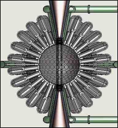
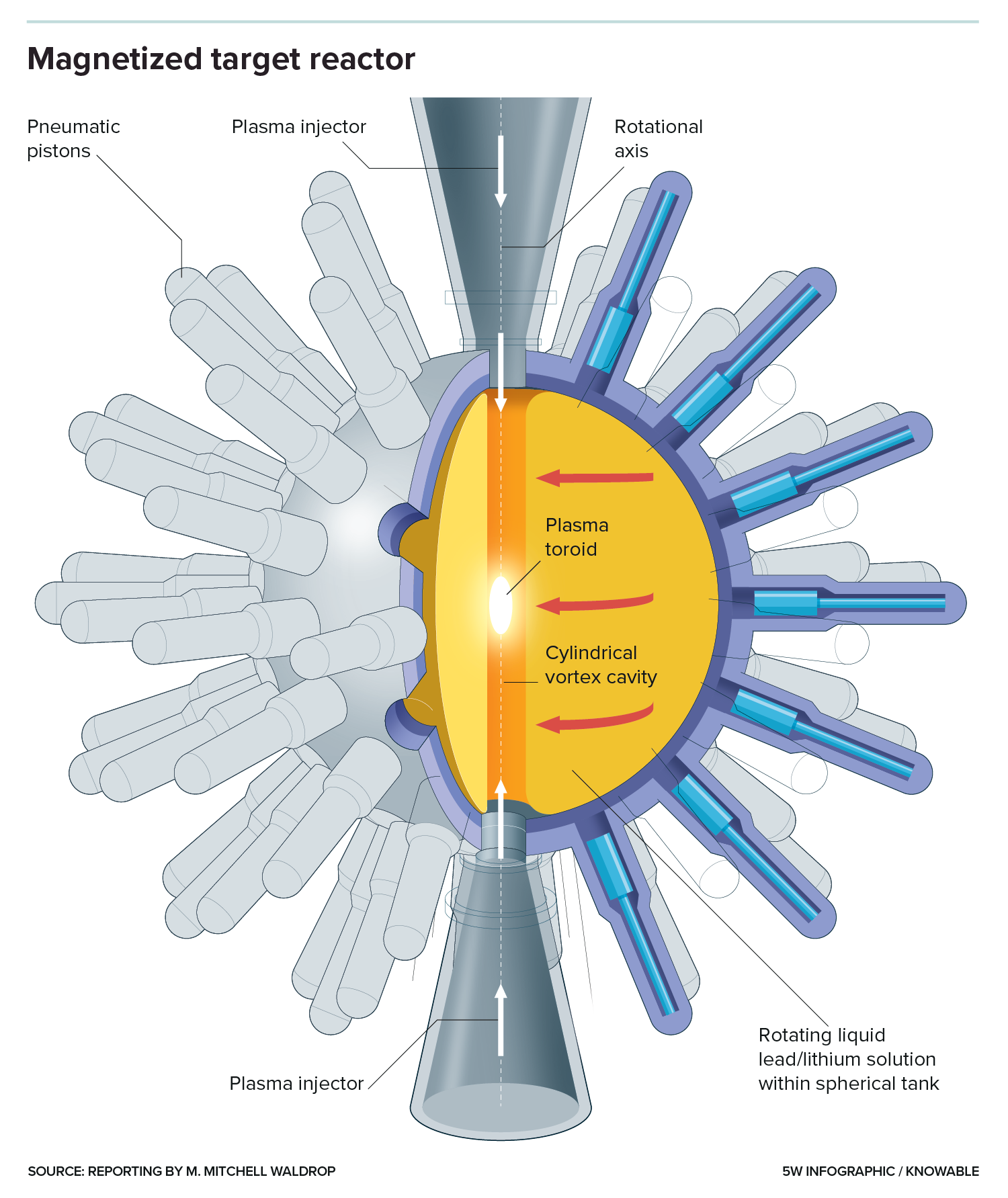
Imagine for a moment that all those rods you see pointed at the core of that fusion reactor were instead fiber optic cables, and that there's a short / small "stand-off" between where the fiber optic cable terminates and where the outer wall of the core begins. Further imagine that the core is some kind of pure Carbon, because Carbon is one of the few materials capable of withstanding the megawatts of power being directed at it.
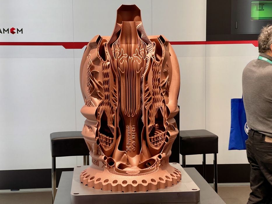
Examples of Carbon or Carbon Fiber / Ceramic Matrix Rocket Engines and Nozzles:


This one was printed in Copper, but the implications of AI-designed rocket engines for efficient thermal power transfer are pretty clear:
Offline
Like button can go here
#39 2025-03-27 17:17:22
- kbd512
- Administrator
- Registered: 2015-01-02
- Posts: 8,243
Re: Focused Solar Power Propulsion
I believe I've posted something like this before, but here's another paper from NASA on advanced Carbon / Carbon-Ceramic rocket engine main combustion chamber and nozzle design work going on at NASA:
Extreme-Temperature Carbon- and Ceramic-Matrix Composite Nozzle Extensions for Liquid Rocket Engines
Materials under development by MSFC and its industry partners have the potential to operate at temperatures up to (or above) 4250°F (2343°C).
2,343C is equal to 2,616.15K, so not quite where we need to be, but much closer than most metals. To be clear, UHTCs (Ultra-High Temperature Ceramics) are required to make this work at 3,200K, our target chamber temperature for 1,000s of Isp using pure LH2 propellant.
They tested these nozzles with LOX/RP1, LOX/LCH4, and LOX/LH2 propellants. The entire point behind development of this tech is that the major parts of the engine are much lighter than Copper-Nickel alloys, Carbon is easier to come by than Copper and Nickel, they're not regeneratively-cooled, they're 3D printed so they cost less, and they're reusable.
Edit:
For comparison purposes, the 3,200K / 2,926.85C chamber temperature required to achieve 1,000s of Isp is most similar to the flame temperature created when MAPP gas is combusted with pure O2. Pure O2/H2 flame temperature is around 2,660C, and pure O2/CH4 flame temperature is around 2,810C.
Last edited by kbd512 (2025-03-27 17:33:35)
Offline
Like button can go here
#40 2025-03-27 20:58:49
- tahanson43206
- Moderator
- Registered: 2018-04-27
- Posts: 21,824
Re: Focused Solar Power Propulsion
For kbd512 re #38 and #39
Thank you for these interesting and helpful examples, and for links to NASA research.
To assist any readers who may be trying to follow this discussion, GW Johnson recommends that the power take-off for this system is the nozzle assembly including the expansion bell. This subsystem can be made of material different from the chamber where heating is to take place. The nozzle and expansion bell are in need of cooling, because the nozzle assembly is going to bear the full load of thrust to be transferred to the vessel.
We have yet to decide how hydrogen is going to be admitted to the heating chamber.
We have yet to decide if any thrust is to be communicated to the vessel via the walls of the heating chamber. GW Johnson suggests that the entire thrust load can be carried by the nozzle assembly, provided that it is (a) strong enough and (b) kept cool.
In the conversation with ChatGPT4o below, I have inquired about the only existing example of what we are trying to do: mirror heated towers to generate electricity.
Solar Mirror Example and Carnot Clarification
Introduction:
The discussion begins with an analysis of the Gemasolar Thermosolar Plant, which uses mirror fields to direct sunlight toward a central receiver where thermal energy is collected and converted to electricity. The purpose of this comparison is to better understand the material and energy transfer processes relevant to our thermal propulsion project.The Gemasolar Example
Materials Used: High-temperature alloys, ceramic materials, and other materials designed to withstand high temperatures and corrosion are employed in the solar receiver.
Heat Transfer Fluid (HTF): The most common HTF is a molten salt mixture of sodium nitrate and potassium nitrate, capable of operating at temperatures up to 600°C. Synthetic oils are used in some cases, but they are less thermally stable than molten salts.
System Efficiency: The overall efficiency of Gemasolar is approximately 20%. This means that of the total solar energy collected by the mirrors, only about 20% is converted into usable electricity.
Energy Losses: About 80% of the collected energy is lost due to thermal losses and inefficiencies in the power conversion cycle.
Total Collected Solar Power: For a net electrical output of 19.9 MW, the total solar energy collected is approximately 99.5 MW.
Clarification of the Carnot Limit
The discussion then turned to the question of whether Carnot efficiency applies to our thermal propulsion system. Here are the findings:
Applicability of Carnot Efficiency: Carnot efficiency applies only when thermal energy is converted to mechanical work or electricity.
Why It Doesn't Apply: Our design intends to directly heat hydrogen gas with photons, rather than converting thermal energy to mechanical or electrical energy. Therefore, the Carnot limit does not apply.
Energy Transfer Efficiency: The key concerns are thermal transfer efficiency, absorption efficiency, and minimizing radiative and convective losses.
40 MW Goal: If the entire 40 MW of collected solar energy can be effectively transferred to the hydrogen gas, this would represent an ideal scenario. In practice, some losses will occur, but not due to the Carnot limit.
Conclusion
In conclusion, while the Gemasolar Thermosolar Plant provides a useful point of comparison for energy collection and transfer, our system differs significantly because it does not involve the conversion of thermal energy to mechanical work. Therefore, the efficiency considerations focus on absorption, thermal transfer, and loss minimization rather than Carnot efficiency.
Would you like me to proceed by estimating the actual energy transfer efficiency achievable with the materials and designs we discussed?
(th)
Offline
Like button can go here
#41 2025-03-27 21:30:21
- GW Johnson
- Member
- From: McGregor, Texas USA
- Registered: 2011-12-04
- Posts: 5,994
- Website
Re: Focused Solar Power Propulsion
The nozzle needs cooling because the most practical materials to build it are metals, and none of those survive 3000 K temperatures. The carbon-based chamber material can survive 3000 K temperatures, and if it has the strength to contain 5-atm-class pressures at such temperatures, then it needs no cooling.
Thermal expansion is going to be a real bugaboo with such a design, if you try to affix the engine to the vehicle at more than one axial station. I wouldn't do that myself, but I would make the mounting point and hardware very strong and stiff, so as to maintain firm control over the thrust vector direction line passing through the vehicle cg, no matter what thermal expansion occurs.
There is a downside and a work-around: firm mounting precludes easy gimbal-type thrust vectoring! You will need some other form of attitude control.
I would suggest attitude control thrusters. You can tap some hydrogen off the main chamber to run them, up nearer the cooler front end,
so the not-so-hot gas is easier to handle with metal tubing and valves.
Attitude thrusters are how we had positive flight control on the 4-stage solid-propellant "Scout" launcher without trying to do flexible-structure vectorable nozzles on the solid motors! Those were very simple, very lightweight hydrogen peroxide monopropellant decomposition thrusters. Electrically-heated catalyst beds in the thruster chambers. This required high-test peroxide, but the storage time before use was short enough to avoid that danger.
Trying to do vectorable nozzles on solid motors was very expensive, usually way too heavy in small sizes, and added multiple possible leak failure modes to the design. Only the strategic-size motors had them. They are usually hydraulically actuated, requiring both substantial motive power and some very heavy equipment to run them.
GW
Last edited by GW Johnson (2025-03-27 21:38:40)
GW Johnson
McGregor, Texas
"There is nothing as expensive as a dead crew, especially one dead from a bad management decision"
Offline
Like button can go here
#42 2025-03-28 09:26:29
- tahanson43206
- Moderator
- Registered: 2018-04-27
- Posts: 21,824
Re: Focused Solar Power Propulsion
Google found numerous citations for the Apollo Command and Service Module.
Here is a snippet from one:
The exhaust nozzle engine bell measured 152.82 inches (Template:Convert/round m) long and 98.48 inches (Template:Convert/round m) wide at the base. It was mounted on two gimbals to keep the thrust vector aligned with the spacecraft's center of mass during SPS firings. The combustion chamber and pressurant tanks were housed in the central tunnel.
https://nasa.fandom.com/wiki/Apollo_Com … ion_System
It seems to me that the need to keep the thrust aligned with the center of mass would be a requirement for the Optical Plane Solar Powered vessel as well, and that leads to the question of how gimbals could be designed for the high thrust expected from this engine?
Update for GW Johnson: Is it feasible to gimbal the entire engine compartment, as an alternative to tradition engine gimbals?
Update from GW Johnson via email: Yes. It is possible to gimbal the entire engine compartment.
Making this design change would simplify design of the rigid structures needed to transfer power from the exhaust port and expansion bell assembly.
It would ** also ** have the benefit of reducing flexing of the fluid feed at the top of the hot bulb. The flexing would still occur, but outside the hot engine compartment. The propellant is coming from the vessel ahead of the engine compartment. It needs to cool the exit port and expansion bell, and then (somehow) makes it's way up to the top of the hot bulb.
Detail: The propellant feed line at the top of the hot bulb needs to be flexible in the linear direction, since the hot bulb is going to expand as it is heated.
(th)
Offline
Like button can go here
#43 2025-03-29 01:15:19
- kbd512
- Administrator
- Registered: 2015-01-02
- Posts: 8,243
Re: Focused Solar Power Propulsion
Keeping the main engine structure rigid is a good way to increase reliability / durability, as well as to decrease complexity and therefore cost / risk. Some of the optical power can be diverted to smaller thrusters to provide equally high-Isp maneuvering thrust from other fixed axis engines. My preference would be to use a small amount of optical power to provide propellant feed pressurization as well. Since the propellant is Hydrogen, fewer joints and separate components reduce the number of leak paths. Tungsten melts at 3,695K, so if we absolutely have to make the engine from metal, it could be made from a Tungsten alloy or Tungsten-based cermet. That said, UHTCs have higher melting points than Tungsten, 4,231K in the case of Hafnium Carbide, and better resistance to Hydrogen. Hafnium Carbide has very pedestrian oxidation resistance, meaning it begins to oxidize at temperatures as low as 430C, but it just so happens to withstand hot and high pressure Hydrogen particularly well. Similarly, pure Carbon can withstand hot Hydrogen fairly well. You can get superlative oxidation or reduction resistance from specific materials, but not both at the same time.
Erosion of refractory carbides in high-temperature hydrogen from ab initio computations
Abstract:
Advanced concepts for in-space propulsion require coatings that are resistant to erosion in high temperature and pressure hydrogen. The erosion of refractory carbides of interest for this application (ZrC, NbC, HfC, and TaC) is investigated using combined ab initio thermodynamic computations and equilibrium product analyses. The carbides are shown to erode through a combination of four governing reactions, the relative extent of which depend on environmental conditions. The product profiles from these reactions are complex but exhibit lower hydrogen saturation at higher temperatures and lower pressures. A metric is derived to determine the applicability of equilibrium analyses for erosion rates, based on experimental conditions. Heritage mass loss experiments on ZrC in hydrogen satisfy the equilibrium criteria, and, correspondingly, the computed equilibrium erosion rate agrees quantitatively. The results suggest that previously postulated non-equilibrium effects, namely the prolonged incongruent vaporization originating from high carbon mobility, do not drive erosion over the hours-long timescales of the experiments. For specific in-space propulsion designs, comparisons of carbide performance show TaC and HfC outperform other carbides and meet the criteria needed to close designs.
I found this paper in the archives:
Studies of Hafnium-Carbide Wafers using a Thermogravimetric Analyzer - Captain Domingo G. Castillo and Mr. Paul F. Jones - Phillips Laboratory - Edwards AFB, California
Abstract:
Solar thermal propulsion can improve orbital transfer and maneuvering of space payloads due to double the performance of specific impulse (Isp) over chemical propulsion systems. Solar thermal can accomplish this increased performance by absorbing concentrated solar energy with very high temperature materials which through conduction heat hydrogen (H2). Hafnium carbide (HfC) is an excellent candidate material as a solar absorber and conductor because of its high melting temperature of 3950°C (7142°F)1. Several reticulated vitreous hafnium carbide wafers with varying porosities were made by a commercial vendor. Samples of these wafers were placed in a Thermogravimetric Analyzer (TGA) and heated from room temperature to 1000°C (1832°F). This would determine any weight gains or losses of the wafers during testing. Results of this analysis show that the hafnium carbide increased in weight approximately 2.5 percent.
I never knew this existed before tonight, but I feel like the fact that I have the same ideas that much smarter and more accomplished aerospace engineers have had, apparently since before I was born, means we're on the right track, and we now have high temperature materials tech that simply did not exist in the 1960s to early 1980s.
SOLAR ROCKET SYSTEM CONCEPT ANALYSIS - Jack A. Boddy - Rockwell International Corporation
Finally... Vindication that this idea for a high-Isp solar thermal rocket is not that far out in left field, it was merely a good idea that never received proper funding and follow-through.
Offline
Like button can go here
#44 2025-03-29 19:53:42
- kbd512
- Administrator
- Registered: 2015-01-02
- Posts: 8,243
Re: Focused Solar Power Propulsion
What is most notable about that solar thermal concept, is that the 1,041s Isp value thought to be achievable using the materials tech of 50 years ago results in roughly a 50% payload mass fraction. That means only 50% of the entire vehicle's all-up wet mass is part of the propulsion system, and the time required to put the vehicle on a TMI (Trans-Mars Injection) flight trajectory, is reduced to around 40 days.
For the 500 passenger 650,000kg interplanetary transport vehicle (ITV) I anticipate will be powered by this propulsion system, that means the propellant mass is around 450,000kg of H2 to provide 4.8km/s of ΔV over 40 days of thrusting, culminating in either a circularized geosynchronous orbit or TMI maneuver. The anticipated dry mass of the vehicle would be around 750t, which includes the ITV, the mylar parabolic mirrors (if fiber optics prove to be mass-unfavorable) that collect and convert photonic power from the Sun into thermal energy, and multiple CFRP H2 propellant tanks, which must be fueled on-orbit by a Starship tanker variant.
Roughly speaking, 450t of LH2, at 70.85kg/m^3, is equal to 6,352m^3 in volume. For comparison purposes, the SLS core stage capacity is about 3,517m^3 between the LOX and LH2 propellant tanks.
Current state-of-the-art Aluminum-Lithium alloy cryogenic tanks would weigh 49,649kg for 6X 10m diameter tanks with a capacity of 634m^3:
STRUCTURAL DESIGN AND SIZING OF A METALLIC CRYOTANK CONCEPT
An equivalent composite cryotank from Boeing had a final mass of 6,696lbs, so 30,373kg for all 10 tanks:
STRUCTURES AND DESIGN PHASE I SUMMARY FOR THE NASA COMPOSITE CRYOTANK TECHNOLOGY DEMONSTRATION PROJECT
The IM7 fiber used by the Boeing / Lockheed-Martin / Northrop-Grumman cryogenic composite demonstrator tanks, which were tested with LH2, is much weaker than Toray T1100G fiber (another fiber tape system used by automated tape layup machines), but the demonstrator program used government furnished fiber and resin intended for consistent design and testing purposes, so may not be representative of flight-weight tanks.
That leaves 69,000kg of mass allocation for the solar thermal collectors and engine(s), in order to arrive at an all-up wet mass of 1,200t, to push the 650t ITV into geosynchronous orbit, whereupon a smaller onboard propellant supply would complete the push to escape velocity.
Offline
Like button can go here
#45 2025-03-30 17:47:03
- tahanson43206
- Moderator
- Registered: 2018-04-27
- Posts: 21,824
Re: Focused Solar Power Propulsion
This topic will be discussed during Google Meeting 2025/03/30
The topic was indeed discussed.
At this point, steering seems to be best done using the ball bearing method used by NASA for the J2 rocket for SLS.
The reason is the need to keep movement of the top of the Hot Bulb as low as possible.
The ball bearing method of steering is the best choice if stability of the top of the Hot Bulb is the primary concern.
(th)
Offline
Like button can go here
#46 2025-04-02 07:01:48
- tahanson43206
- Moderator
- Registered: 2018-04-27
- Posts: 21,824
Re: Focused Solar Power Propulsion
In this conversation I asked ChatGPT4o to estimate the thrust that might be produced by a rocket given only the flow of propellant and the temperature of the exhaust. I was surprised to see the value produced.
You said:
Thank you! I am delighted you were able to estimate thrust given so little information! Please prepare your answer as a BBCode report. As a reminder, we can only show red, blue and darkgreen.ChatGPT said:
You're very welcome! Here's your thrust estimation formatted as a BBCode report, using only red, blue, and darkgreen as allowed:Thrust Estimate for Hydrogen-Based Rocket
Objective:
Estimate the thrust produced by a rocket engine operating in vacuum. The engine flows hydrogen at 2 kilograms per second, and the exhaust temperature is 3000 Kelvin.Given Parameters:
Mass flow rate = 2 kg/s
Exhaust temperature = 3000 K
Propellant = Hydrogen gas (assumed ideal)
Ambient pressure = 0 Pa (vacuum conditions)
Method:
We use the ideal gas-based formula to estimate exhaust velocity:Exhaust velocity (ve) = sqrt[ (2 * gamma / (gamma - 1)) * (R * T / M) ]Where:
gamma (specific heat ratio) = 1.4
R (gas constant) = 8.314 J/mol·K
M (molecular mass of hydrogen) = 0.002016 kg/mol
T (exhaust temperature) = 3000 K
Substitute the values into the formula:
 ve ≈ sqrt[ (2.8 / 0.4) * (8.314 * 3000 / 0.002016) ]
ve ≈ sqrt[ 7 * 12,377,063 ]
ve ≈ sqrt[ 86,639,444 ]
ve ≈ 9308 m/s
Thrust Calculation:
Use the basic thrust formula:
Thrust = mass flow rate * exhaust velocity Thrust = 2 kg/s * 9308 m/s Thrust ≈ 18,616 Newtons[center]✅ Estimated Thrust: 18.6 kilonewtons (kN)[/center]
Remarks:
This is a simplified estimate assuming ideal conditions in a vacuum.
No nozzle losses, friction, or real-gas deviations were considered.
Still, this estimate is quite realistic for high-efficiency thermal rockets using hydrogen.
Let me know if you’d like a version comparing this to chemical rockets or adding ion propulsion for hybrid analysis!
Since AI can make mistakes, i am hoping our NewMars members with expertise in this area will double check the work.
Note: According to unitconverters.net, 18,616 Newtons is 1.8983037021 metric force-tons.
That is more than the 1/2 force-ton I'd been expecting.
Update after email from GW Johnson ... a preliminary evaluation indicates the result may be high. More updates to follow.
(th)
Offline
Like button can go here
#47 2025-04-03 06:46:54
- tahanson43206
- Moderator
- Registered: 2018-04-27
- Posts: 21,824
Re: Focused Solar Power Propulsion
In another topic, kbd512 pointed out that hydrogen will disassociate to atomic form at 3000 Kelvin. I asked Google's Gemini to "think" about that effect, and it came back with what looks to me like reasonable observations and recommendations.
Conversation with Gemini
Hi Gemini! Thank you for your help with earlier inquiries! Today I'm hoping you might help with a rocket design problem. The operating conditions are starting to become clear, as we study the requirements. We are planning to use hydrogen in a manner similar to the NERVA rocket, but our heating source will be solar energy instead of nuclear fission. The temperature of the exhaust is intended to be on the order of 3000 Kelvin. One of our team members has asked about disassociation of hydrogen at that temperature. I am unsure of how that natural process might affect performance. On one hand, the mass of individual molecules might be reduced which I would think might improve performance, but on the other hand the energy consumed by disassociation might detract from the temperature of the gas. Do you have any guidance for us?
***Hello! I'm happy to help you with your solar-thermal rocket design problem. This is a very interesting application of solar energy and the challenges you're facing regarding hydrogen dissociation are indeed critical.
Here's a breakdown of the relevant considerations:
1. Hydrogen Dissociation at High Temperatures:
The Reaction: At elevated temperatures, molecular hydrogen (H 2 ) dissociates into atomic hydrogen (H) according to the following equilibrium:
H 2 ⇌2H
Temperature Dependence: The degree of dissociation increases significantly with temperature. At 3000 K, a substantial fraction of the hydrogen will be in the atomic form.
Energy Consumption: The dissociation process is endothermic, meaning it requires energy. This energy is absorbed from the heat provided by the solar concentrator, effectively reducing the available thermal energy for thrust.
2. Impact on Rocket Performance:
Increased Specific Impulse (Potential Benefit):
Specific impulse (I sp ) is a measure of rocket engine efficiency, proportional to the exhaust velocity.
Exhaust velocity is related to the square root of the temperature and inversely related to the square root of the molar mass of the exhaust gases.
Atomic hydrogen (H) has half the molar mass of molecular hydrogen (H 2 ). Therefore, if a significant portion of the exhaust is atomic hydrogen, the average molar mass of the exhaust is reduced, potentially leading to a higher specific impulse.
Reduced Temperature (Potential Detriment):The endothermic dissociation process absorbs heat, as you mentioned. This means that for a given amount of solar energy input, the actual exhaust temperature will be lower than it would be without dissociation.
A lower temperature reduces the exhaust velocity and, consequently, the specific impulse.Equilibrium Considerations:
The dissociation reaction is an equilibrium process. The actual composition of the exhaust gas (the ratio of H to H 2 ) will depend on both temperature and pressure.As the gas expands through the rocket nozzle, the pressure decreases, which will shift the equilibrium towards more atomic hydrogen.
Recombination:
As the extremely hot hydrogen exits the nozzle, it will begin to recombine. This recombination releases the energy that was used to dissociate the hydrogen. If this recombination occurs within the nozzle, then some of the energy can be recovered and used to increase thrust. If the recombination occurs outside of the nozzle, then that energy is wasted.3. Guidance for Your Design:
Thermodynamic Modeling: You'll need to perform detailed thermodynamic calculations to accurately predict the equilibrium composition of the hydrogen gas at the operating temperature and pressure. This will allow you to determine the actual average molar mass and the amount of energy consumed by dissociation.
Nozzle Design: Carefully design the nozzle to maximize the expansion ratio and promote recombination within the nozzle. This can help recover some of the dissociation energy and improve efficiency.
Solar Concentrator Optimization: Maximize the temperature of the hydrogen before it enters the nozzle. This will reduce the relative energy loss due to dissociation.
Considerations of Materials: At 3000K, the selection of materials that can withstand the extreme temperatures becomes very difficult.
Computational Fluid Dynamics (CFD): using CFD software to simulate the flow of the hydrogen through the nozzle will allow you to see the effects of recombination, and optimize the nozzle design.In summary:
Hydrogen dissociation can both increase and decrease specific impulse.
The net effect depends on the balance between the reduced molar mass and the reduced temperature.
Accurate thermodynamic modeling and careful nozzle design are crucial for optimizing performance.I hope this information is helpful for your rocket design. Good luck with your project!
***Thank you for your helpful reply! I'll pass it along. The suggestion of CFD analysis is a good one. It crosses my mind that others may well have done such CFD analysis, so there may be results available. In the mean time, best wishes for similar success as you assist your many other customers!
***You're very welcome! I'm glad the information was helpful. You're absolutely right about the potential availability of existing CFD analyses. Research papers and technical reports on high-temperature gas dynamics, particularly those related to aerospace and propulsion, might contain relevant data. Searching for terms like "hydrogen dissociation CFD," "high-temperature nozzle flow," or "reacting flow CFD" could yield useful results.
And thank you for your kind wishes! I appreciate it. If you have any further questions or need additional assistance in the future, please don't hesitate to ask.
My observation is that design of the rocket nozzle appears to be the most relevant aspect of the consequence of disassociation.
The suggestion that atomic hydrogen will recombine after entering the expansion bell is interesting.
In my opinion (at this point) this is an academic question that is surely going to be worth a paper for an enterprising PhD student.
It is interesting but since our goal is to design a system that someone will pay to build, and the team working on this is small, I'd hoping we can invest our time and energy on questions that are on the critical path to achievements.
(th)
Offline
Like button can go here
#48 2025-04-03 21:31:03
- tahanson43206
- Moderator
- Registered: 2018-04-27
- Posts: 21,824
Re: Focused Solar Power Propulsion
This evening I asked Gemini for assistance in trying to think through the problem of design of a propulsion system for the Solar Power Space Tug.
We've been given four parameters to start with:
1) propellant is LH2
2) Desired output temperature is 3000 K
3) Mass flow rate is 2 kg/s (with 1 kg/s as a fall back)
3) Power supply is 40 MW
Gemini came up with an element I'd not been aware of before. The hydrogen must be in physical contact with the Hot Bulb for some reasonable period of time, in order to absorb thermal energy to reach 3000 Kelvin.
In our initial experiments this evening, with hypothetical chamber sizes, the dwell time was insufficient.
Todo item: How long did hydrogen spend in NERVA to reach 3000 Kelvin?
Todo item: What was the flow rate of hydrogen through NERVA?
Given 40 MW of solar energy, what amount of heating of LH2 is possible?
In other words, given a flow rate of 2 kg/s and a power input of 40 MW, what elevation of temperature is possible?
Gemini showed that if we reduce the mass flow to 1 kg/s we increase the temperature of the hydrogen but it was still way below 3000 K.
(th)
Offline
Like button can go here
#49 2025-04-04 07:15:39
- tahanson43206
- Moderator
- Registered: 2018-04-27
- Posts: 21,824
Re: Focused Solar Power Propulsion
This morning I decided to follow up on yesterday's interaction with Gemini....
In that interaction, Gemini brought up the issue of dwell time for hydrogen inside the heating chamber.
In the session reported below, we considered NERVA as a model, and Gemini suggested some resources where there might be information available. The NERVA team has a very similar problem. They had to design a heat transfer system that would heat hydrogen to very high temperatures at a very high rate. Our problem is similar, but made much more difficult because the thermal energy comes from outside the engine and not inside.
Thank you again for your previous assistance! Yesterday, we began to look at the challenge of designing a rocket engine for a use case that is not common. The engine would consume hydrogen as a propellant, and it would obtain energy from outside, instead from combustion like a chemical rocket, or internal heating such as NERVA. In that conversation, you pointed out that time is required for hydrogen to gain thermal energy by conduction from the hot material of which the engine is composed. Today I'm hoping you might be willing to help us think through how this system would work. Specifically, I am wondering if we can determine how long the hydrogen molecules must spend inside the heat engine to reach the desired temperature. For example, are there any records of the NERVA project that are accessible to the public? I'm wondering if such records might help us today?
***That's a really insightful question, and it gets to the heart of the engineering challenges for your solar-thermal rocket! You're right, the amount of time the hydrogen spends in contact with the heated surfaces is crucial for effective heat transfer.
Let's break down how to think about this and whether NERVA resources might help:
Estimating Hydrogen Residence Time for Heating:
Determining the exact residence time needed for hydrogen to reach 3000 K through contact heating is a complex problem involving several factors:
Heat Transfer Coefficient: This depends on the properties of the hydrogen (density, viscosity, thermal conductivity, specific heat), the flow velocity, and the geometry and surface finish of the heating channels. Higher flow rates generally lead to better heat transfer due to increased turbulence, but also reduce residence time.
Temperature Difference: The greater the temperature difference between the heated engine components and the hydrogen, the faster the heat transfer rate. However, as the hydrogen heats up, this difference decreases.
Heat Capacity of Hydrogen: Hydrogen has a relatively high specific heat, meaning it takes a significant amount of energy to raise its temperature.
Geometry of the Heat Exchanger: The design of the channels through which the hydrogen flows (length, diameter, shape, surface area) directly impacts the contact time and the overall heat transfer area.
Material Properties of the Engine: The thermal conductivity and heat capacity of the engine material determine how effectively heat can be transferred to the surface in contact with the hydrogen.
A Simplified Conceptual Approach:
While a precise calculation requires detailed engineering analysis, we can think about it conceptually:
Energy Required: Calculate the amount of energy needed to raise a given mass of hydrogen from its initial state to 3000 K. This involves using the specific heat of hydrogen over that temperature range. Keep in mind that the specific heat of hydrogen changes with temperature and will also be affected by dissociation at higher temperatures.
Rate of Heat Transfer: Estimate the rate at which heat can be transferred from the engine material to the hydrogen. This will depend on the heat transfer coefficient and the contact area.
Residence Time: The required residence time would then be related to the total energy needed divided by the rate of heat transfer.
The Challenge of Conduction Alone:As you pointed out yesterday, relying solely on conduction from the engine walls to heat a rapidly flowing gas to such a high temperature is very challenging. Gases are generally poor thermal conductors. This is why NERVA and similar concepts use designs with very high surface area to volume ratios, creating thin channels and often incorporating porous materials or fuel elements with large exposed surfaces to maximize heat transfer.
NERVA Project Records and Their Potential Help:
You're on a great track thinking about the NERVA project! While NERVA used nuclear fission as its heat source, the fundamental challenge of transferring large amounts of heat to a hydrogen propellant stream at high flow rates is very similar to your solar-thermal concept.
Here's how NERVA resources might be helpful:
Reactor and Fuel Element Design: NERVA reactors had intricate designs for their fuel elements, which were engineered to maximize heat transfer to the flowing hydrogen. Examining these designs (if publicly available) could provide inspiration for your heat exchanger geometry.
Look for information on fuel element dimensions, channel sizes, and surface area.Performance Data: Publicly available reports might contain data on hydrogen flow rates, temperature increases achieved within the reactor core, and the residence times of the hydrogen in the heated sections. This could give you a sense of the order of magnitude for the required contact times.
Materials Science: NERVA pushed the boundaries of high-temperature materials. Understanding the materials used and their thermal properties could be relevant for your solar receiver and heat exchanger design.
Thermal Analysis Techniques: Reports might detail the analytical and experimental techniques used to study heat transfer within the NERVA reactors. This could guide your own analysis efforts.
Accessing NERVA Information:
NASA Technical Reports Server (NTRS): This is a primary source for publicly released NASA documents, including many related to the NERVA program.
Department of Energy (DOE) OpenNet: Since NERVA had nuclear aspects, some reports might be available through the DOE's open access portal.
University Libraries and Archives: Some universities that were involved in the NERVA project might have archival collections of reports and documents.
Historical Societies and Museums: Organizations focused on space history might have relevant materials.
Key Considerations for Your Solar-Thermal Design:
Direct Solar Heating of Hydrogen: Instead of relying solely on conduction from a solid structure, could you explore designs where the concentrated solar energy directly heats the hydrogen gas (perhaps through a transparent window or within a specially designed receiver)? This could potentially bypass some of the limitations of conductive heat transfer.
Heat Transfer Enhancement Techniques: Consider incorporating features in your heat exchanger design that enhance heat transfer, such as turbulators or porous media, if the pressure drop can be managed.
Trade-offs: There will always be trade-offs between residence time, flow rate, pressure drop, and engine size and weight. Your design process will involve finding the optimal balance among these factors.
Finding specific data on hydrogen residence times in NERVA to reach a certain temperature might be challenging, as those details would be tightly coupled to the specific reactor design and operating conditions. However, studying the overall design philosophies and performance characteristics of NERVA can undoubtedly provide valuable insights as you tackle the heat transfer challenges in your innovative solar-thermal rocket.
Keep exploring those resources – you never know what gems you might find! Good luck with your research!
(th)
Offline
Like button can go here
#50 2025-04-04 07:36:23
- tahanson43206
- Moderator
- Registered: 2018-04-27
- Posts: 21,824
Re: Focused Solar Power Propulsion
This is a follow up to Post #49
In Post #49, Gemini hinted that it might be possible to deliver some energy to hydrogen using radiation. While hydrogen is transparent to most light wavelengths, I decided to follow up:
I have posted a transcript of our session this morning, and hope our team members will be able to review it. In the mean time, I have a follow up question: In your reply you hinted that it might be possible to heat hydrogen gas with a method other than conduction. I am under the impression that hydrogen gas is almost transparent to light. Are you aware of any research showing that hydrogen can be heated by radiation?
***You're right, in its ground state, molecular hydrogen (H 2 ) is largely transparent to visible and near-infrared radiation, which is the dominant part of the solar spectrum. The absorption and emission spectra of hydrogen in the visible range correspond to electronic transitions that require specific, relatively high-energy photons.
However, your intuition that direct radiative heating might be possible isn't entirely off-base! Here's why:
Ultraviolet (UV) Absorption: Hydrogen does absorb strongly in the ultraviolet region of the electromagnetic spectrum. Solar radiation does contain a portion of UV, and if your solar concentrator can focus this part of the spectrum effectively, some direct heating through electronic excitation and subsequent energy transfer via collisions could occur. However, the fraction of solar energy in the deep UV is relatively small at Earth's surface (though it's more significant in space before atmospheric filtering).
Vibrational and Rotational Transitions: While electronic transitions require higher energy photons, molecules also have vibrational and rotational energy levels. Transitions between these levels occur at lower energies, typically in the infrared and microwave regions of the spectrum. Molecular hydrogen has some weak absorption bands in the infrared due to vibrational and rotational transitions. If the concentrated solar energy has a significant component in these wavelengths, and if the hydrogen gas is at a high enough density and path length, some direct heating can occur through the excitation of these modes, followed by collisional energy transfer that increases the translational kinetic energy (temperature) of the gas molecules.
Two-Photon Absorption and Non-Linear Effects: At very high intensities of radiation, such as those achievable with highly focused solar concentrators (especially in space), non-linear optical phenomena like two-photon absorption can become significant. In this process, a molecule simultaneously absorbs two photons whose combined energy matches an allowed transition. This could potentially allow for absorption of lower-energy photons (e.g., visible or near-infrared) leading to heating. However, these effects are generally weak unless the light intensity is extremely high.
Impurities and Additives: If the hydrogen gas contains even trace amounts of other substances (impurities or intentionally added particles), these could absorb radiation and then transfer heat to the surrounding hydrogen through collisions. This is a less direct method of heating the hydrogen itself but could be a practical consideration.
High Temperatures and Dissociation: As the hydrogen gas begins to heat up through contact with the engine materials or through initial weak radiative absorption, the dissociation process you mentioned earlier comes into play. Atomic hydrogen has different absorption characteristics than molecular hydrogen, and the plasma formed at very high temperatures interacts strongly with electromagnetic radiation. So, while starting with cold H 2 and directly heating it radiatively with sunlight is challenging, once some heating and dissociation occur, the resulting mixture might become more absorptive.
Research and Applications:
While directly and efficiently heating pure, cold molecular hydrogen with unconverted sunlight via radiation alone is difficult, the concept of using concentrated solar energy to heat a working fluid (which could be hydrogen) is the basis of solar thermal rockets. However, in most designs, the energy transfer mechanism involves:
Concentrating Sunlight: A large mirror or array of mirrors focuses sunlight onto a receiver.
Absorbing Energy: The receiver, made of a high-temperature material, absorbs the concentrated solar energy and heats up.Heat Transfer to Propellant: The cold propellant (hydrogen in your case) is then passed through the heated receiver, where it is heated primarily by conduction and convection from the hot surfaces.
Direct Solar Absorption Concepts:
There is ongoing research into more direct solar absorption methods for heating gases, often involving:
Seeding the gas with absorbing nanoparticles: These nanoparticles absorb the radiation and then transfer heat to the surrounding gas through collisions.
Using specific wavelengths of laser light: Lasers can be tuned to specific absorption lines of the gas, allowing for more efficient and selective heating. This is less relevant for broadband solar radiation.
In the context of your solar-thermal rocket:
It's likely that the primary mechanism for heating your hydrogen to 3000 K will still be through contact with a very hot surface that has absorbed the concentrated solar energy. However, understanding the potential for even weak direct radiative heating could be beneficial for optimizing the design of your solar receiver and the flow path of the hydrogen.
I recommend looking into research on:
Solar thermal propulsion: Pay attention to the designs of solar receivers and heat exchangers.
Gas-phase radiative heat transfer: While hydrogen is weakly absorbing, studies on high-temperature gases and plasmas might offer insights.
Laser heating of hydrogen: While not directly applicable to broadband sunlight, it can illuminate the fundamental absorption properties of hydrogen.
While hydrogen's transparency to much of the solar spectrum presents a challenge for direct radiative heating, exploring the nuances of its interaction with different wavelengths and under extreme conditions could spark innovative ideas for your engine design.
Sources and related content
Emission spectrum of hydrogen (video) - Khan AcademySolar Radiation & Photosynthetically Active Radiation - Environmental Measurement Systems - Fondriest Environmental
Vibrational Energy
bmc1.utm.utoronto.ca
Two-photon absorption: an overview of measurements and principles
opg.optica.org
Concentrating Solar-Thermal Power Basics - Department of Energy
Thank you for this additional development of the idea of passing some energy to hydrogen using radiation. And thanks for the additional insights about work done by others in this specialty.
***You're very welcome! It's a fascinating area, and the more you delve into the intricacies of how hydrogen interacts with energy, the more possibilities you might uncover. Best of luck as you continue your research and design process!
It seems to me unlikely that an engine designed to heat hydrogen primarily using conduction can be adapted to include radiation, the insight that atomic hydrogen is more receptive to radiation heating is potentially useful. For example, if radiation could be supplied to the gas/plasma after it exits the throat of the nozzle, perhaps the additional energy might cause increased pressure against the expansion bell.
(th)
Offline
Like button can go here