New Mars Forums
You are not logged in.
- Topics: Active | Unanswered
Announcement
#26 2024-09-11 06:35:47
- tahanson43206
- Moderator
- Registered: 2018-04-27
- Posts: 23,850
Re: Vacuum plus Water Gravity plus Air Compression Energy Storage
For SpaceNut re #25
Thank you for your careful study of Calliban's engineering sketches.
Those are the best he has created so far! The color shading helps to clarify the operation of the equipment, as you have confirmed with your post.
You are absolutely correct! If you owned one of these systems, you would start with the lower chamber full of water, and the upper chamber empty. You would store energy by moving water from the lower chamber to the upper. If the air pressure in both chambers were the same (ie, ambient) then the energy stored would simply be due to lifting the water against gravity. What makes the system more capable is that Calliban has shown the lower chamber as sealed, so work must be invested in pulling water out of the lower tank in addition to gravity. That combination provides two sources of stored energy.
What I have proposed is a third energy store mechanism. If the upper chamber is sealed, then the pressure of gas in that chamber will increase as water is pumped from below. Unlike with gravity and vacuum stores, which are fixed by the dimensions of the apparatus, the upper chamber can be given a starting pressure greater than ambient, so the energy stored can be greater that would otherwise be the case.
Thus, in a system that employs all three storage modes, the pump will be storing energy as:
1) Gravity lift
2) Vacuum pull
3) Compression push
What I have asked for and not yet seen is a computation of the storage capacity of a system designed with these three elements.
To try to focus on a single configuration, I have offered the following specifications:
1) Mass of water: 1 ton
2) Lift between tanks: 10 meters
3) Initial pressure in upper tank: ambient
This combination of elements should yield a fixed quantity of energy. I expect the stored energy will be well under 1 kilowatt hour.
What is needed is an exact measure of what can be achieved with this configuration of components and operating procedures.
Once we have the energy store that is possible with the starting conditions, we can increase various factors to see what effect changes have on performance.
Until we have a firm foundation of data to work with, we are just waving our hands, as so often happens in free flowing discussions.
(th)
Offline
Like button can go here
#27 2024-09-11 07:05:24
- Calliban
- Member
- From: Northern England, UK
- Registered: 2019-08-18
- Posts: 4,279
Re: Vacuum plus Water Gravity plus Air Compression Energy Storage
I can't remember if I raised this idea before. Pressure vessel regulations apply to all vessels containing a pressure of greater than 0.5bar. For very low pressure CAES, at pressures <0.5bar, we could use gravity pressure vessels to store compressed air. Something like the image shown below. In this case, we are digging a hole ~2m deep and using the extracted material in addition to waste rock and rubble, to counter balance internal pressure.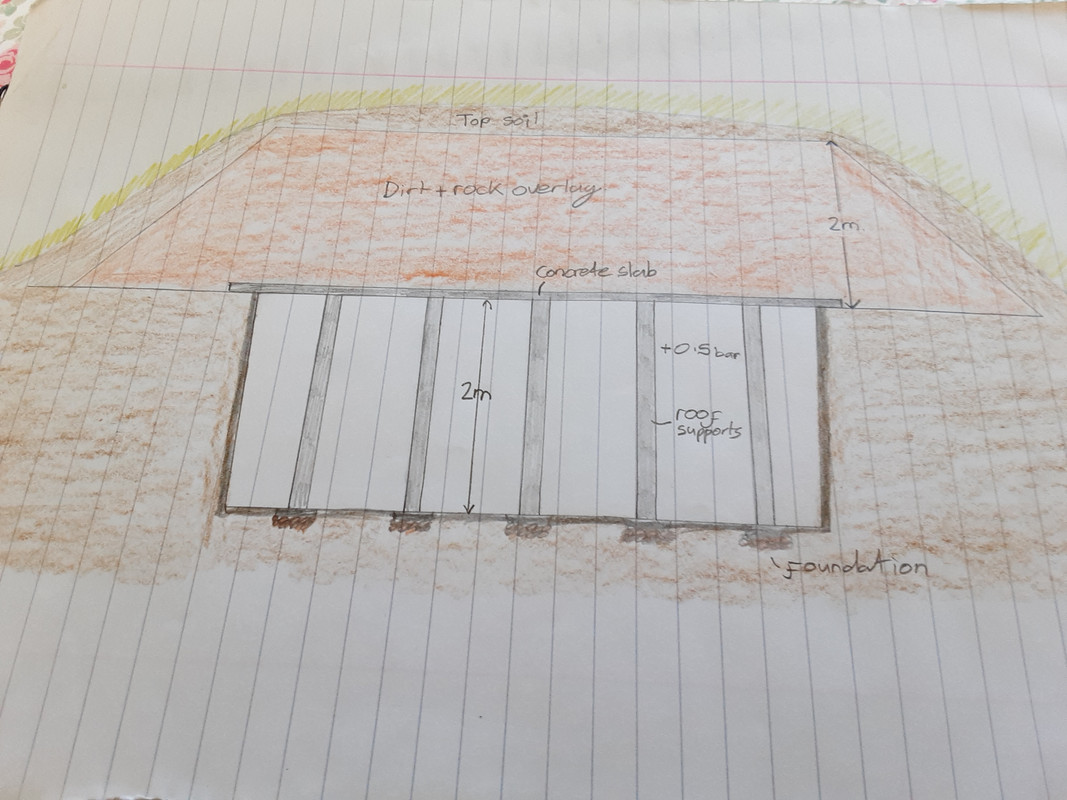
Air with a pressure of 0.5bar(g) has low energy density - between 40-60KJ/m3. To store 1kWh of energy would require a volume of 72m3, or a hole 6m x 6m x 2m deep. But we could have a CAES system that stored energy both in vacuum and positive pressure. To store 1kWh, we would have a vacuum tank with volume 36m3 with a fully charged pressure of 0.5bar(a) and an underground positive pressure CAES gravity vessel with a fully charged pressure of 1.5bar(a). Energy would be released by discharging air between the two vessels, with an air turbine inbetween.
One advantage that this system provides is that it keeps water out of the tanks, along with all of the problems that creates. Another advantage is that the heat generated by compression is kept within a thermal store that is insulated by metres of soil and rock. The same air is compressed and released each cycle, from the below ground gravity vessel into the vacuum tank, allowing moisture content to be tightly controlled.
Last edited by Calliban (2024-09-11 07:15:58)
"Plan and prepare for every possibility, and you will never act. It is nobler to have courage as we stumble into half the things we fear than to analyse every possible obstacle and begin nothing. Great things are achieved by embracing great dangers."
Offline
Like button can go here
#28 2024-09-11 19:35:36
- SpaceNut
- Administrator
- From: New Hampshire
- Registered: 2004-07-22
- Posts: 30,201
Re: Vacuum plus Water Gravity plus Air Compression Energy Storage
Part of the equations are Horsepower required to pump water.
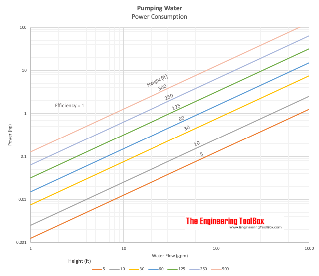
That said we need to know that the power created is greater than that to which we see and still have energy from creation that is excess due to the vacuum and gravity.
Pumping Water - Required Horsepower
Horsepower required to pump water.Energy imparted to water by the pump is called water horsepower - and can be calculated as
Pwhp = q h SG / (3960 μ)
where
Pwhp = water horsepower (hp)
q = flow (gal/min)
h = head (ft)
SG = 1 for water Specific Gravity
μ = pump efficiency (decimal value)
Horsepower can also be calculated as:
Pwhp = q dp / (1715 μ)
where
Pwhp = water horsepower (hp)
dp = delivered pressure (psi)
Offline
Like button can go here
#29 2024-09-13 07:34:29
- Calliban
- Member
- From: Northern England, UK
- Registered: 2019-08-18
- Posts: 4,279
Re: Vacuum plus Water Gravity plus Air Compression Energy Storage
On Mars, CAES will have an advantage over comparable systems on Earth. The triple point of CO2 is -56.6°C and 0.518MPa (~5 atm). This means that Martian CO2 can be stored as a dense liquid when cooled and pressurised. This allows economical storage of compressed CO2 in above ground steel tanks, something that it more difficult to achieve using air on Earth. Air can be stored as liquid as well, but liquid nitrogen is a cryogen and is liquid at temperatures far beneath Earth ambient. On Mars, -56°C is above typical night time temperature. The critical temperature of CO2 is 31°C. This would allow concentrated sunlight to superheat CO2 back into dry high-pressure vapour. Whilst the low ambient pressure on Mars complicates CAES, it also allows excellent expansion ratio during power recovery.
"Plan and prepare for every possibility, and you will never act. It is nobler to have courage as we stumble into half the things we fear than to analyse every possible obstacle and begin nothing. Great things are achieved by embracing great dangers."
Offline
Like button can go here
#30 2024-09-14 07:46:04
- SpaceNut
- Administrator
- From: New Hampshire
- Registered: 2004-07-22
- Posts: 30,201
Re: Vacuum plus Water Gravity plus Air Compression Energy Storage
water falling gives a level of generation as well
https://www.engineeringtoolbox.com/hydr … _1359.html
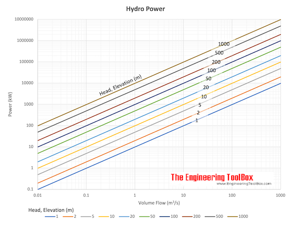
So we have both equations for up and down.
So the down equation - energy surplus must be still greater than the level required to pump it back up to the top tank.
The theoretically power available from falling water can be expressed as
Pth = ρ q g h
where
Pth = power theoretically available (W)
ρ = density (kg/m3) (~ 1000 kg/m3 for water)
q = water flow (m3/s)
g = acceleration of gravity (9.81 m/s2)
h = falling height, head (m)
Offline
Like button can go here
#31 2024-09-14 08:11:17
- tahanson43206
- Moderator
- Registered: 2018-04-27
- Posts: 23,850
Re: Vacuum plus Water Gravity plus Air Compression Energy Storage
For SpaceNut re the water component of energy storage in this topic....
Thanks for the link to the Engineering Toolbox, and for the chart showing large scale performance that might be expected.
For all...
Thermal management is a significant factor in the efficiency of any storage system where thermal energy is involved. That is certainly the case in this topic, where compression of gas is an activity that occurs as energy is stored. In another topic, Void recently showed us a paper from 2008 which spent some time talking about the need to preserve the thermal energy accumulated in the compressed gas chamber.
In a small system such as the one set up for this topic, it seems to me possible that insulation might be set around the upper chamber so that the thermal energy invested in the compression chamber is preserved.
As a corollary... the upper chamber might be enclosed in a vacuum chamber to improve insulation, although it may turn out that insulation strategies short of vacuum may work "well enough".
(th)
Offline
Like button can go here
#32 2024-09-14 10:44:14
- tahanson43206
- Moderator
- Registered: 2018-04-27
- Posts: 23,850
Re: Vacuum plus Water Gravity plus Air Compression Energy Storage
For Calliban (all others welcome to contribute)...
This topic was inspired by the idea of using vacuum as an energy store.
Now, by a convoluted process involving one of Void's ideas, I am back wondering if a better use of vacuum might be at the ** top ** of the stack, as insulation around the compressing cylinder.
In this scenario, we are moving a ton of water out of the outer sleeve of a two cylinder configuration, and pumping that water into a cylinder that is inside the one that is going to contain vacuum, with the distinction that the inner cylinder contains gas that is going to be compressed to store the actual energy.
The inner cylinder will become hotter and hotter as the water flows in, until some practical limit is reached.
Given these conditions, and the outer pipe diameter of 1 meter, can you compute an optimum configuration for this concept?
I would propose an elevation (or depth) of 10 meters just to provide some working room.
1) How much energy can be stored? (obviously this will depend upon the starting pressure in the gas cylinder so set it as high as possible)
2) What temperature will the gas in the upper chamber reach?
Given:
A) One ton of water
B) Outer diameter of 1 meter
C) Total system elevation of 10 meters
(th)
Offline
Like button can go here
#33 2024-09-14 13:44:52
- SpaceNut
- Administrator
- From: New Hampshire
- Registered: 2004-07-22
- Posts: 30,201
Re: Vacuum plus Water Gravity plus Air Compression Energy Storage
The tank at the top will have Compressed gas energy storage. as a result of pumping the water from the lowest tank to the top if the amount of water is greater than that of the volume in the bottom tank as the pressure will force the water back downward to the lower tank unless it's restricted until a max level of pressure is achieve. The shutting off of the water flowing only creates a minor vacuum in that tank as a result of the pumping of it.
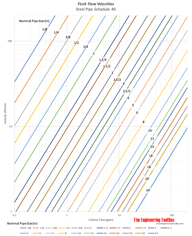
The restriction of fluid flowing other than the turbine and valve is the size of the piping that is used which is contained in this topic Power Distribution by pipelines on Mars and others.
Water Flow based on Pipe Size Inside and Outside Diameters
Offline
Like button can go here
#34 2024-09-14 13:56:24
- tahanson43206
- Moderator
- Registered: 2018-04-27
- Posts: 23,850
Re: Vacuum plus Water Gravity plus Air Compression Energy Storage
For SpaceNut re #33
Thank you for your continued interest in and support of this topic!
The size of the piping seems (to me at least) to be a major concern for the designer.
One observation I would offer is that the designer has a fixed quantity of water to deal with, so the designer has the opportunity to size the chambers to meet the need. The bottom chamber would (presumably) have a volume of one cubic meter, and the upper tank would have a volume of at least 2 cubic meters, so there is volume for the gas to be compressed. It might turn out that the volume in the upper chamber should be greater. This would be the province of ** real ** engineers, and fortunately we have more than one in the forum membership.
(th)
Offline
Like button can go here
#35 2024-09-14 14:08:13
- SpaceNut
- Administrator
- From: New Hampshire
- Registered: 2004-07-22
- Posts: 30,201
Re: Vacuum plus Water Gravity plus Air Compression Energy Storage
Potential energy of the upper tank is mass x gravity and pressure
Energy created by the turbine as water flows to the lower tank is flow rate
Energy to be used via the homeowner kwhr
Energy used by the pump movement of water kwhr
Offline
Like button can go here
#36 2024-09-14 14:10:17
- tahanson43206
- Moderator
- Registered: 2018-04-27
- Posts: 23,850
Re: Vacuum plus Water Gravity plus Air Compression Energy Storage
For SpaceNut ... re #35
I don't see the compression in your list of energy stored.
I also don't see the vacuum energy storage in your list.
The complete system will include all three elements.
(th)
Offline
Like button can go here
#37 2024-09-14 14:13:27
- SpaceNut
- Administrator
- From: New Hampshire
- Registered: 2004-07-22
- Posts: 30,201
Re: Vacuum plus Water Gravity plus Air Compression Energy Storage
Pressure is the compression as the water flows from the pumping of it to the top tank.
Just like vacuum is created from the pumping action but only if the flow from the top tank is stopped.
Otherwise, the pumping unchecked is aided by less resistance to water flow.
Offline
Like button can go here
#38 2024-09-14 14:28:53
- tahanson43206
- Moderator
- Registered: 2018-04-27
- Posts: 23,850
Re: Vacuum plus Water Gravity plus Air Compression Energy Storage
For SpaceNut re #37
Can you put up some numbers to go with your text?
Please show:
Energy stored moving water up the column from the base (10 meters)
Energy stored pushing against gas in upper chamber
Energy stored pulling water out of lower chamber against vacuum
The total you provide is the total energy storage capability of the proposed system.
Please be careful to use the specifications for the test:
1) water 1 ton
2) elevation 10 meters
3) Upper pressure ... variable but start with ambient pressure for first version.
You'll need a volume for the upper chamber. Please start with 2 cubic meters, so that one will be filled with water from below, and the other will contain the gas that is compressed. Thus, the gas will be compressed to 1/2 it's original volume in this scenario.
(th)
Offline
Like button can go here
#39 2024-09-14 18:18:45
- SpaceNut
- Administrator
- From: New Hampshire
- Registered: 2004-07-22
- Posts: 30,201
Re: Vacuum plus Water Gravity plus Air Compression Energy Storage
update
1) water is 1,000 kg/m3 for water which is 1 metric ton.
2) power theoretically available (W) = 0 water flow as its not moving but if you use 1 m3/s rather than a 0
then it will be 9.81 m/s2 * 1 m3/s * 1,000 kg/m3 * 10 m = 98,000 w or 98 Kw/sec.
3) a vacuum is at the top means that water will not flow until the pump turns on to push the water out, for that energy is not present until a power source is used.
4) a vacuum at the bottom means that it will pull all of the tank until full / once air pressure in the top expands and drops as the water flows out. Which allows the turbine to turn and create power as long as the water is flowing. Power will drop as the water pressure drops as the top tank is emptied.
To get answers on the pump size and power we will need to convert units for the equations
https://www.engineeringtoolbox.com/unit … html#Power
We will need pipe diameters and a turbine generator to finish up a design.
so a minute means 98kw/s / 60 sec = 1,633 w/min and for the hour / 60 once more gets 27 w/hr which is quite tiny due to the quick flow rate. when we are looking for power in kilowatt we will need
Example - Energy in Elevated Water Volume
10 m3 volume of water is elevated 10 m above the turbine. The potential energy in the water volume can be calculated asW = (1000 kg/m3) (10 m3) (9.81 m/s2) (10 m)
= 981000 J (Ws)
= 981 kJ (kWs)
= 0.27 kWh
Due to 10 times more water to flow...
Offline
Like button can go here
#40 2024-09-14 19:08:32
- tahanson43206
- Moderator
- Registered: 2018-04-27
- Posts: 23,850
Re: Vacuum plus Water Gravity plus Air Compression Energy Storage
For SpaceNut re #39
Thanks for continuing to work on the energy storage system of this topic.
Let's not worry about taking energy OUT of the system right now. What I'm hoping we can do is to determine exactly how much energy can be stored in the system.
We have members who are good at creating images.
Void creates drawings that illustrate massive structures in space, as well as smaller ones.
Calliban is noted for the very high quality hand drawn engineering sketches he's been sharing with us. In recent times he has added color shading to make the drawings even more understandable.
GW Johnson has created many images to illustrate his course materials and other presentations.
It appears that neither you nor I are skilled in creating images from scratch.
I'll try once again with words to try to convey what this system would look like.
Before I do that, I'd like to point out that the best machine to move water up the pipe is a small piston driven pump. It does not have to be fast at all. The power is going to be coming from wind or solar, and for our purposes I will specify a quantity of water to be moved in a single piston operation of 1 cubic centimeter of water. That means 1000000 piston operations will move the entire contents of the lower chamber to the upper chamber. The work the little piston engine will be doing is going to increase over time. The reason is that the pressure in the receiving chamber at the top of the pipe is going to increase, and the vacuum at the bottom of the assembly will increase. The gravity lift will remain constant throughout the process.
The pipe from bottom to top need not be large in diameter at all. It will provide passage for 1 cubic centimeter of water at a time! The pipe does need to be strong enough to hold up to the pressure that is going to build on the output side of the pump.
The receiving chamber at the top of the pipe needs to be at least two cubic meters in size, because it must hold the ton of water plus the gas which will be compressed as water is added to the upper chamber.
I hope this helps.
All I'm looking for is energy stored.
None of the other factors that might be interesting are needed at this point.
(th)
Offline
Like button can go here
#41 2024-09-15 14:27:06
- SpaceNut
- Administrator
- From: New Hampshire
- Registered: 2004-07-22
- Posts: 30,201
Re: Vacuum plus Water Gravity plus Air Compression Energy Storage
Starting with a tank that is empty will have in the space 1 Atm no matter how large the tank is. So, let's just fill a random size tank with 1 meter of water and only choose the height as the fixed dimension that matters. If we start at 2m tall and fill just 1-meter, the air pressure will rise to 2 Atm that the air occupies.
Now let's run the same experiment with a 3-meter-tall tank we have a result of 1.5 atm per meter that the air will occupy.
Ok we fill a 2-meter tank and vent the air we have zero pressure. But if we lower the level with 1 meter with the tank closed, we will have a -1 Atm in the void that is created after pumping it out. So now just assume that the tank is 3-meter tall and filled and we lower the level to just 1 meter then the void of 2 meters will have a -2 Atm.
Offline
Like button can go here
#42 2024-09-15 17:06:36
- tahanson43206
- Moderator
- Registered: 2018-04-27
- Posts: 23,850
Re: Vacuum plus Water Gravity plus Air Compression Energy Storage
For SpaceNut re #41
Thanks for thinking about the upper tank and the rise in pressure in the gas section.
If we take your example, and set a 1 cubic meter tank at the bottom, and set a 2 cubic meter at the bottom, we can run a 10 meter line between them.
We seem to be approaching the ability to compute the numbers for this contraption.
The water in the bottom tank will be lifted 10 meters against gravity, so we have that quantity ready to go up on the board.
The water in the bottom will create a vacuum as it is pulled out of the bottom tank, and the force of the vacuum will cause the pump to work harder.
I just realized I don't know if the force required to remove each cubic centimeter of water increases or remains constant.
As each cubic centimeter of water is forced into the upper tank, the pressure of the air above the water will increase from 1 atm to 2, as you predict.
Thus, in that case, the work required to pump that cubic centimeter of water will increase.
Each cubic centimeter will require:
1) force against gravity (constant)
2) force against vacuum (which is unclear to me at this point)
3) force against air pressure which increases from 1 atm to 2 atm over the run.
By any chance, do you have any idea if the force required to move water out of the lower tanks will increase or remain constant?
My vision of the mechanism is that water will drop into the pump chamber thanks to gravity. The pump piston will push the water in it's barrel through a one-way valve, which will be strong enough to withstand the accumulating pressure in the upper tank.
A drawing would be helpful.
In the meantime, we'll just have to make do with words.
(th)
Offline
Like button can go here
#43 2024-09-15 17:55:57
- SpaceNut
- Administrator
- From: New Hampshire
- Registered: 2004-07-22
- Posts: 30,201
Re: Vacuum plus Water Gravity plus Air Compression Energy Storage
In artesian well control design, a one-line jet pump or equivalent is used to move water from the non-pressurized water storage tank which is the bottom tank into a water pressure tank which is what we have with the top tank. It has a typical 20-40 or 30-50 psi trip point to turn on and off the jet pump that is in the well. Of course, that is an open loop system as we are closing the loop by creating energy with the released water that will travel down to the lower tank through a generator unit. While in a well we have 1 Atm above the well it's the column of water that build pressure to aid the pumping unit.
Offline
Like button can go here
#44 2024-09-15 19:27:55
- tahanson43206
- Moderator
- Registered: 2018-04-27
- Posts: 23,850
Re: Vacuum plus Water Gravity plus Air Compression Energy Storage
For SpaceNut re #43
Thanks for details of the artesian well that you have experience with!
And thanks for noting that when we advance to thinking about recovery of energy, we have a model to study.
However, we have not yet achieved the immediate goal, which is totaling up the energy that can be stored in the system as we've been designing it.
At the moment, and as of the last round, we have a two cubic meter receiving tank at the top of a 10 meter well.
The two meter tank starts with contents of air at 1 bar (ie, ambient).
At the bottom of the well we have a one cubic meter tank that is full of water.
The plan of operation is to pump water from the lower tank into the upper one until the lower tank is empty.
As you have predicted, the pressure in the air in the upper tank will rise from 1 bar to 2 bars, while the temperature of that air rises.
We have not attempted to deal with the temperature rise, but that is of interest in the nearby CAES topic.
What I expect is that as the little piston pump at the bottom of the 10 meter pipe pushes each cubic centimeter of water up the pipe, it will have to work harder.
What I'm not clear on is whether the vacuum being created in the bottom tank has any effect on the increase of work to be done by the pump.
It is possible that it is not the vacuum that causes the pump to work .... it may be the back pressure from the receiving tank that causes all the extra work.
There may be a way to compute all this but at this point I don't know what the method might be.
(th)
Offline
Like button can go here
#45 2024-09-17 18:16:06
- SpaceNut
- Administrator
- From: New Hampshire
- Registered: 2004-07-22
- Posts: 30,201
Re: Vacuum plus Water Gravity plus Air Compression Energy Storage
Store of pressure or is defendant on size of chamber and period that measurement is done.
https://nooutage.com/hydroele.htm
https://attradev.ncat.org/wp-content/up … design.pdf
So off grid water power creators use an old washing machine motor rewound to producr 600 w at 24 v like this unit
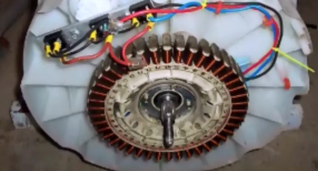
the magnetic disk that goes over the coils is not shown.
Offline
Like button can go here
#46 2024-09-17 19:59:09
- tahanson43206
- Moderator
- Registered: 2018-04-27
- Posts: 23,850
Re: Vacuum plus Water Gravity plus Air Compression Energy Storage
For SpaceNut re output from the stored energy system....
Thanks for showing us examples of adaptation of an interesting washing machine motor to generate power.
We still have not performed the mathematics so we know how much energy could be stored by the proposed system, but whatever that power may be, delivery into a 24 volt DC "grid" seems sensible.
I asked Google for examples of 24 volt systems and it came back with this list:
Original
Simpler
24-volt direct current (VDC) power has many applications, including:
Vehicles
24-volt battery systems are used in larger vehicles, such as trucks, buses, and boats, because of their higher power needs and long cable runs. Trolling motors for fishing boats are also a common application.
Industrial equipment
24-volt systems are suitable for high-power applications, such as industrial equipment, because they can deliver more power than 12-volt systems.
Personal use products
24-volt DC motors are used in many personal use products, such as hair dryers, footbaths, and stick massagers.
Audio and lighting
24-volt power supplies can be used for audio and lighting applications.
Medical and communication
24-volt power supplies can be used in medical and communication applications.
Uninterrupted power supply (UPS)
A UPS can provide 24-volt power for critical equipment for several hours during a power failure.
Control panels
24-volt control can reduce the need for lockout/tagout and often times control panels can be serviced while still energized.
24V Power Supplies: Product Catalog & Selection Guide
Feb 7, 2022 — A 24V Power supply can change AC to DC and the voltage level can be adjusted at the same time. There are a variety of s...
FSP Group
24V Battery-powered Applications | RECOM
Mar 24, 2023 — These factors all translate into many value propositions in the real-world applications tabled in this article. Whethe...
RECOM Power
Understanding VDC Output Power Supplies and Their Uses in Electronics Design
Apr 4, 2022PCB Design & Analysis
Show all
Generative AI is experimental.
(th)
Offline
Like button can go here
#47 2024-09-17 20:01:37
- tahanson43206
- Moderator
- Registered: 2018-04-27
- Posts: 23,850
Re: Vacuum plus Water Gravity plus Air Compression Energy Storage
It is time to remind everyone this topic is hoping for numbers to go with all the words we have poured out so far...
Here is the request:
For SpaceNut re #41
Thanks for thinking about the upper tank and the rise in pressure in the gas section.
If we take your example, and set a 1 cubic meter tank at the bottom, and set a 2 cubic meter at the bottom, we can run a 10 meter line between them.
We seem to be approaching the ability to compute the numbers for this contraption.
The water in the bottom tank will be lifted 10 meters against gravity, so we have that quantity ready to go up on the board.
The water in the bottom will create a vacuum as it is pulled out of the bottom tank, and the force of the vacuum will cause the pump to work harder.
I just realized I don't know if the force required to remove each cubic centimeter of water increases or remains constant.
As each cubic centimeter of water is forced into the upper tank, the pressure of the air above the water will increase from 1 atm to 2, as you predict.
Thus, in that case, the work required to pump that cubic centimeter of water will increase.
Each cubic centimeter will require:
1) force against gravity (constant)
2) force against vacuum (which is unclear to me at this point)
3) force against air pressure which increases from 1 atm to 2 atm over the run.By any chance, do you have any idea if the force required to move water out of the lower tanks will increase or remain constant?
My vision of the mechanism is that water will drop into the pump chamber thanks to gravity. The pump piston will push the water in it's barrel through a one-way valve, which will be strong enough to withstand the accumulating pressure in the upper tank.
A drawing would be helpful.
In the meantime, we'll just have to make do with words.
(th)
Offline
Like button can go here
#48 2024-09-18 16:37:30
- SpaceNut
- Administrator
- From: New Hampshire
- Registered: 2004-07-22
- Posts: 30,201
Re: Vacuum plus Water Gravity plus Air Compression Energy Storage
The storage is not a number but a variable that is determined based on the tank volumes, water amount, internal and external capability for pressure and vacuum as Caliban has already indicated due to implosion and explosion of the tanks and piping due to those levels.
So, you must decide on the level of work that must be produced to determine those values in the above statement. You must determine the power levels for the pump and generator in order to size all other aspects of a design storage and use.
One can make the storage the size of a walnut under extreme pressures or vacuum, or you can have a mountain size unit will be minimal of those.
The original numbers have already been given and they produce very little energy.
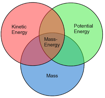
You must also include Gravity Energy Storage as they are part of the energy system by default.
We are still talking about the most efficient form of storage and conversion rate for Electricity, Work, and Power
Summary of Force, Work and Power
Force = Energy applied to an object(Measured in Newtons).
Work = Force X Distance, or the amount of heat transferred (Measured in Joules or calories).
Power = Work/Time (Measured in Watts)
Various Energy Units
1 calorie (thermochemical) = 4.184 J
1 Btu = 251.9958 calories
1 Btu (thermochemical) = 1054.35 J
1 kilowatt-hour (kWh) = 3.6 x 10⁶ J
1 kilowatt-hour (kWh) = 3412 Btu (IT)
1 therm = 100,000 Btu
1 electron-volt = 1.6022 x 10⁻¹⁹ J
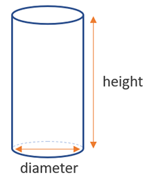
https://www.wikihow.com/Calculate-the-V … a-Cylinder
https://www.gigacalculator.com/calculat … ulator.php
https://en.wikipedia.org/wiki/Working_fluid
generator type for the working fluid determines inlet rate from the volume
This is also where we get into how much power wattage can I get for how long of a duration before refilling the volume.
Pressure control is achieved in hydraulic systems by metering the flow of a fluid into or out of a constrained volume to create force such as a jack for an automobile.
https://www.hi-force.com/en-uk/blog-det … te-a-force
https://www.hydraulicspneumatics.com/te … c-pressure
A pump adds energy to oil in any of the three ways, as described by Bernoulli’s equation:
Hydraulics pneumatics Com Sites Hydraulics pneumatics com Files Dec mc Eq1
where P is the pressure,
ρ is the density,
v is the velocity,
g is the acceleration due to gravity, and
h is the elevation.
More equations on the page
https://www.machinerylubrication.com/Re … re-vs-flow

Of course, this is moving the fluid to make pressure from the reservoir to the location to be moved.
Sensing functions that are computer controller-ed used to produce a response for more or less power seems to be good to have.
While I am thinking about gravity and water as the mass that we can make use of.
https://www.micro-hydro-power.com/water-turbines.htm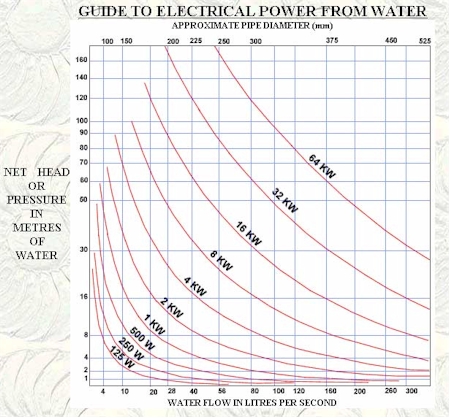
Power (watts) = Head (m) x Flow (litres/sec) x 9.81 (gravitational constant ‘g’) A typical water to wire efficiency is around 70%, so you should multiply the result by 0.7 to get the actual amount of electricity that you can expect from the site.
https://www.builditsolar.com/Projects/H … fRiver.htm
Power = (1/2)(Turbine Efficiency) (Water Density) (Turbine Flow Area) (Water Velocity)^3
Normally the mass is what will cause the turbine to move so knowing the amount and time is a flow rate.
Rotation is required and that is torque for the turbine.
Of course, when you need RPM's we are looking at that flow rate as it relates to the torque values.
https://www.studysmarter.us/explanation … al-motion/
https://en.wikipedia.org/wiki/Torque
Power in rotational systems (torque and frequency of a rotation)-527.png)
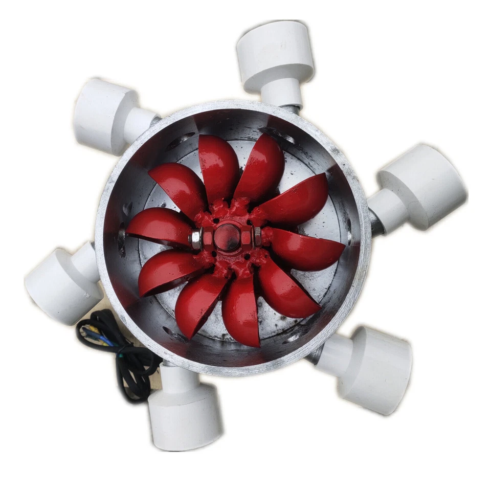
power generation from the top to the bottom means we want to make 2 -3 times what we would use. So I am looking at the 3kw turbine as it would cost less than $400 on ebay turbine
.


Offline
Like button can go here
#49 2024-09-18 17:52:47
- tahanson43206
- Moderator
- Registered: 2018-04-27
- Posts: 23,850
Re: Vacuum plus Water Gravity plus Air Compression Energy Storage
For SpaceNut re #48
Thank you for a terrific tool box for our project!
I am wondering what information you could possibly need.
We've defined the problem with precision. As far as I know there is nothing missing, that would prevent computation of the energy storage capacity of the proposed system.
For all our readers, here are the specifications again:
1) The mass of water is one ton. It has **always** been one ton.
2) The elevation between the tank at the bottom of the shaft, and the one at the top is 10 meters.
3) The size of the tank at the bottom is precisely one cubic meter.
4) The size of the tank at the top is precisely two cubic meters.
The pipe between the tanks is not a critical element, except that it must be able to accommodate the slow movement of water from the lower tank to the upper one. If the size of the pipe is important for some reason let's give it a size that you are comfortable with. The material of which the pipe is made does not seem important to me (at least). All we need are sizes of the vessels, and the distance between them.
With this information I am hoping the members of this group will be able to compute the total energy that can be stored. Whatever the amount is it is going to be under one kilowatt hour, and it may be well under.
The work to be done by the little piston pump at the bottom of the shaft will increase over time. We know this because the pressure in the upper tank will increase from 1 atmosphere to 2. The lift against gravity will remain constant.
I am not clear on what effect pulling against the vacuum at the bottom of the shaft will have.
Let's see if we can put up some numbers for this simple test system.
(th)
Offline
Like button can go here
#50 2024-09-18 19:20:06
- SpaceNut
- Administrator
- From: New Hampshire
- Registered: 2004-07-22
- Posts: 30,201
Re: Vacuum plus Water Gravity plus Air Compression Energy Storage
Since working in units of meter is called for then the Ton is a metric ton or 1,000 kg which is 1,000 liters.
Storage is the units in a stagnant or none moving state.
The pipe sizes are also critical for the flow rates desired not only to maintain filling the tanks but for also pumping them to the top once more to close the loop.
Try to fill a 1-liter bottle in 1-sec. from the water facet and then you have a comparison point as that tap is at 40 to 50 psi. or https://www.aqua-calc.com/convert/press … -kilopasca https://calculatorpack.com/water-pressure-calculator/
Power turbin water exits out the bottom of the unit so its going to be mounted at the top of the down hill tank.
this shows the water re-entering the stream after exiting the pump
This is a turbine that one can build as a DYI if that is your choices.
Power generated would connect to a battery system and be draw out of it by the pump is we are unable to build a Ram pump.
otherwise, the battery then connects to the invertor to make 60 hz voltage for use.
Offline
Like button can go here