New Mars Forums
You are not logged in.
- Topics: Active | Unanswered
Announcement
#76 2024-06-30 12:05:45
- GW Johnson
- Member
- From: McGregor, Texas USA
- Registered: 2011-12-04
- Posts: 5,615
- Website
Re: Spin Launch SpinLaunch Vacuum Launches Centrifuge Launched Mass
The photo in post 75 shows the spin launch carrier vehicle, a streamlined dart. The side of it opens up laterally like a clamshell, to release the payload and its booster rocket. The clamshell closes and the dart falls back, finally slowed by a chute, for a landing near the launch site.
This kind of trajectory apogees in altitude (zero vertical velocity) with virtually-zero horizontal velocity. The payload's booster rocket has to take it from essentially zero speed to orbital speed, horizontally, in the desired direction. Since it is above the sensible atmosphere, and radius from the Earth's center is not changing during the burn, there are no gravity and drag losses to cover. Circular orbit speed up there is about 7.7-something to 7.8 km/s. A transfer ellipse from that point instead of just circularizing, has a higher velocity requirement.
In essence, the unpowered carrier dart has as its payload the actual payload, plus a booster rocket capable of delivering 7.8 km/s dV or more, while carrying that actual payload. That booster rocket will be quite a bit bigger than the actual payload. The rocket equation demands that.
Acceptable payload fractions and the booster stage Isp's determine how many stages are required. Bear in mind that to withstand 5000-10,000 gees laterally, the inert fractions for the booster stages are going to be much higher than you are used to seeing! Strength always costs more mass. It is inevitable.
While I hope they succeed, it is my opinion that the considerations I just described render the potential of this launch technique to be quite limited.
GW
Last edited by GW Johnson (2024-06-30 12:11:38)
GW Johnson
McGregor, Texas
"There is nothing as expensive as a dead crew, especially one dead from a bad management decision"
Offline
#77 2024-06-30 19:00:41
- SpaceNut
- Administrator

- From: New Hampshire
- Registered: 2004-07-22
- Posts: 29,310
Re: Spin Launch SpinLaunch Vacuum Launches Centrifuge Launched Mass
https://www.spinlaunch.com/orbital
shows that its tipped
Offline
#78 2024-07-01 09:30:25
- tahanson43206
- Moderator

- Registered: 2018-04-27
- Posts: 18,142
Re: Spin Launch SpinLaunch Vacuum Launches Centrifuge Launched Mass
In looking at the video SpaceNut found, at 2:40 minutes... we see that the rockets are liquid, not solid.
(th)
Offline
#79 2024-07-01 16:02:42
- GW Johnson
- Member
- From: McGregor, Texas USA
- Registered: 2011-12-04
- Posts: 5,615
- Website
Re: Spin Launch SpinLaunch Vacuum Launches Centrifuge Launched Mass
Solid or liquid, the components must be supported and stressed for centrifugal gee in the 10,000 gee class. It appears with the angled launch, they do not intend to recover and re-use the carrier vehicle. BTW, its pointed nose will be blunted by air friction heating on the way up. Sharp points do not stay sharp in hypersonic flow.
GW
PS -- that last sentence is also why I do not believe you can build an air inlet for high hypersonic flight in the atmosphere, or for flying into space with airbreathing propulsion. If the sharpness goes away, so does the inlet pressure recovery, and its mass ingestion characteristics. Its drag also goes up; a lot!
Not to mention that thrust is a factor times ambient air pressure, with any imaginable type of airbreathing jet engine. 10 times nothing is still nothing, no matter which way you try to "spin" the situation. No thrust is simply no climb rate and/or pathwise acceleration. Isp doesn't matter once that obtains.
Last edited by GW Johnson (2024-07-01 16:08:16)
GW Johnson
McGregor, Texas
"There is nothing as expensive as a dead crew, especially one dead from a bad management decision"
Offline
#80 2024-07-01 17:14:09
- tahanson43206
- Moderator
- Registered: 2018-04-27
- Posts: 18,142
Re: Spin Launch SpinLaunch Vacuum Launches Centrifuge Launched Mass
For GW Johnson re #79 and topic in general...
I plead guilty to having led this discussion astray due to the incorrect assumption the SpinLaunch rocket package would use solid fuel rockets. My incorrect assumption was based in large part on the plans of Dr. John Hunter for his massive gas gun, which would have been able to use solid fuel because the acceleration planned for that system was along the center line of the projectile.
Having acknowledged that the SpinLaunch system appears to be intended to use liquid propellants, please assess the potential of hypergolic propellants to achieve LEO, given the lean-to-the-East inclination of the proposed SpinLaunch orbital system.
We can hopefully assume that the pointed nose of the projectile will survive to fly again, but if it becomes rounded as you predict, that component can be replaced at the maintenance facility.
This discussion is not about air breathing engines of any kind, although I recognize that discussion of air breathing engines is going on in other topics.
Please assess the potential of hypergolic fuels to complete the SpinLaunch orbital mission.
(th)
Offline
#81 2024-07-01 18:39:45
- SpaceNut
- Administrator
- From: New Hampshire
- Registered: 2004-07-22
- Posts: 29,310
Re: Spin Launch SpinLaunch Vacuum Launches Centrifuge Launched Mass
The flight path at first will be faster along a similar route but where the stage for the payload takes over is about in the same location as the falcon 9 profile. From when the second stage is no more, and we are using the kick stage.

The kinetic energy once launched will exit the system but begin to slow as it climbs with drag decreasing as it rises.
Offline
#82 2024-07-01 19:54:03
- tahanson43206
- Moderator
- Registered: 2018-04-27
- Posts: 18,142
Re: Spin Launch SpinLaunch Vacuum Launches Centrifuge Launched Mass
For SpaceNut re #81 ... thanks for this interesting and helpful flight profile!
Here is a preliminary assessment by ChatGPT regarding the revised understanding of the SpinLaunch orbital concept, as revealed by the video you found:
Hello Again... I'd like to enlist your assistance in thinking through the implications of a clarification our little group received regarding the SpinLaunch orbital configuration. We have learned (a) that the toss will be inclined to the East, which means that the payload package will have some momentum toward the East, and (b) the second and third stage rockets will be liquid instead of solid fueled. We presume the fuel for these stages will be hypergolic. We can see in the company video that the fuel containers are spherical, which would imply that the G forces will be distributed against the outside wall of the spheres during spinup before launch. As you evaluate this scenario, I'm wondering if you can predict if hypergolic fuels can survive 10,000 G's and then perform their thrust mission after the outer casing reaches apogee. We have learned that the outer casing is to open like a clamshell and release the payload and two stages above the sensible atmosphere.
Key Points to Consider
1. Inclined Launch and Eastward Momentum:
- The payload package will have an initial momentum toward the east due to the inclined launch.
- This eastward momentum will aid in achieving an orbital trajectory, leveraging Earth's rotation.2. Liquid-Fueled Second and Third Stages:
- The second and third stages will use liquid fuel, likely hypergolic, which ignites spontaneously upon contact with an oxidizer.
- These stages will be contained in spherical fuel containers during spinup.3. 10,000 G Forces on Hypergolic Fuels:
- The spherical fuel containers will experience immense G forces during spinup, which will press the fuel against the outer walls of the spheres.
- After reaching apogee, the outer casing will open like a clamshell, releasing the payload and stages.Evaluating Hypergolic Fuels under 10,000 G's
Physical Properties of Hypergolic Fuels:
- Density and Viscosity: These fuels are relatively dense liquids with moderate viscosity.
- Phase Stability: Hypergolic fuels remain stable in liquid form over a range of temperatures and pressures.Effects of High G Forces:
1. Fuel Distribution:
- The centrifugal forces will cause the fuel to be evenly distributed against the inner walls of the spherical containers.
- This distribution should not affect the chemical stability of the fuel, provided the containers are designed to withstand such forces.2. Structural Integrity:
- The spherical design is advantageous as it uniformly distributes stress, minimizing the risk of structural failure.
- High G forces may induce minor physical changes, such as increased pressure at the fuel-container interface, but these are typically within the design tolerances of aerospace-grade materials.3. Ignition and Combustion:
- Upon release from the clamshell, the reduced G forces will allow the fuel to flow toward the combustion chamber.
- Hypergolic fuels are known for their reliable ignition characteristics, which should remain unaffected by prior exposure to high G forces, provided no phase change (e.g., vaporization) occurs.Predicted Performance After Release
1. Clamshell Release:
- The outer casing opening like a clamshell at apogee will subject the payload to a momentary period of microgravity.
- This should allow the fuel to settle naturally within the feed systems of the second and third stages.2. Thrust Performance:
- The spontaneous ignition property of hypergolic fuels ensures reliable engine start once the fuels come into contact with each other.
- The pre-launch high G forces should not impair the performance, as the fuels are designed to operate under varying conditions in space.3. Structural Considerations:
- Ensure that fuel lines and tanks are designed to withstand both the spinup G forces and the subsequent microgravity environment.
- Pay particular attention to the material compatibility and structural integrity under both extreme acceleration and space conditions.Conclusion
Hypergolic fuels should be capable of surviving the 10,000 G forces during the spinup phase, given that their physical and chemical stability is maintained, and the containers are designed to handle such stresses. Upon release at apogee, the transition to a microgravity environment should allow for normal fuel flow and combustion, ensuring the stages can perform their thrust mission as intended.
If you have any specific concerns or further details you'd like to discuss, feel free to let me know!
(th)
Offline
#83 2024-07-02 12:37:40
- tahanson43206
- Moderator
- Registered: 2018-04-27
- Posts: 18,142
Re: Spin Launch SpinLaunch Vacuum Launches Centrifuge Launched Mass
As an update ... In a Google lookup I ran today, it appears that the orbital vehicle is intended to put up to 200 kg in orbit as the payload. This means the mass of the vehicle itself will be considerably greater.
For GW Johnson ... is the spreadsheet capable of dealing with a three stage rocket such as this, with the unusual circumstance of the first stage consuming no fuel? I would think the rocket equation would have a hard time with this.
Would it make more sense to model a two stage rocket that is already in motion?
If you ignite the second stage while the vehicle still has momentum heading up and East, then the transition would be similar to a traditional rocket after the first stage separates.
(th)
Offline
#84 2024-07-02 16:04:56
- GW Johnson
- Member
- From: McGregor, Texas USA
- Registered: 2011-12-04
- Posts: 5,615
- Website
Re: Spin Launch SpinLaunch Vacuum Launches Centrifuge Launched Mass
Rocket equation analysis makes ABSOLUTELY NO sense for the "first stage", that being where the carrier ends up launching whatever it contains. There would be speed, altitude, and path angle data for that point, and I have NEVER seen any credible data, not yet.
From that point, you could do rocket equation analyses of however many stages the rocket has, that pushes the actual payload into orbit from there. But you have to make some educated guesses for what the gravity and drag losses might be. And they would be only guesses.
GW
GW Johnson
McGregor, Texas
"There is nothing as expensive as a dead crew, especially one dead from a bad management decision"
Offline
#85 2024-07-02 18:29:19
- tahanson43206
- Moderator
- Registered: 2018-04-27
- Posts: 18,142
Re: Spin Launch SpinLaunch Vacuum Launches Centrifuge Launched Mass
For GW Johnson re #84
Thanks for engaging with me on this important topic...
It ** sounds ** as though you think the spreadsheets can deal with the "missing" first stage.
Let's assume the package departs the launcher at 5000 mph and follows a 45 degrees angle toward the East, and let us suppose the apogee of the parabola is at 100,000 feet.
Let's also accept the reported satellite payload as 200 kg.
Can the spreadsheet compute the components in the package, by working backward from the result (200 kg in orbit) to the end of the first stage boost?
You don't need to be reminded, but for our readers who do not follow topics as closely as members, we are pursuing this option to see if it might provide a competitive cost for the McGregor Space Systems Orbiting Fuel Depot. (MSSOFD).
Working backward:
5) 200 kg satellite in orbit
4) Third stage hypergolic rocket boost
3) Second stage hypergolic rocket boost
2) First stage fling by SpinLaunch arm
1) Entire package is secured to SpinLaunch arm at rest.
The goal of the exercise is to confirm that substituting electric current for the first stage for the traditional solid or liquid fuel rocket stage will result in cost savings for the customer.
The company goal of launching every hour means that there will be 24 different planes in work. That would presumably be advantageous to customers, who can launch to meet the refueling depot in one of those 24 planes.
(th)
Offline
#86 2024-07-02 19:39:09
- SpaceNut
- Administrator
- From: New Hampshire
- Registered: 2004-07-22
- Posts: 29,310
Re: Spin Launch SpinLaunch Vacuum Launches Centrifuge Launched Mass
At the top of the "parabola" the rocket which was launch is now approaching a zero forward speed as gravity is about to pull it back to earth.
https://www.calctool.org/kinetics/range … ile-motion
https://www.desmos.com/calculator/on4xzwtdwz
From that point the kick stage needs to run until it gets to orbit picking up speed until it's at the desired orbit.
The Falcon 9 first stage separates from the second stage at an altitude of approximately 80 kilometers (50 miles). This happens approximately 161 seconds int flight but due to exit speed of the launch the new spot will be at a different time and altitude. Means that separation happens at 100.2 km and 7400 km/hr (2055.6 m/s).
100,000 ft is 30.48 km which means we are only half the distance for comparison.
https://www1.grc.nasa.gov/beginners-gui … -equation/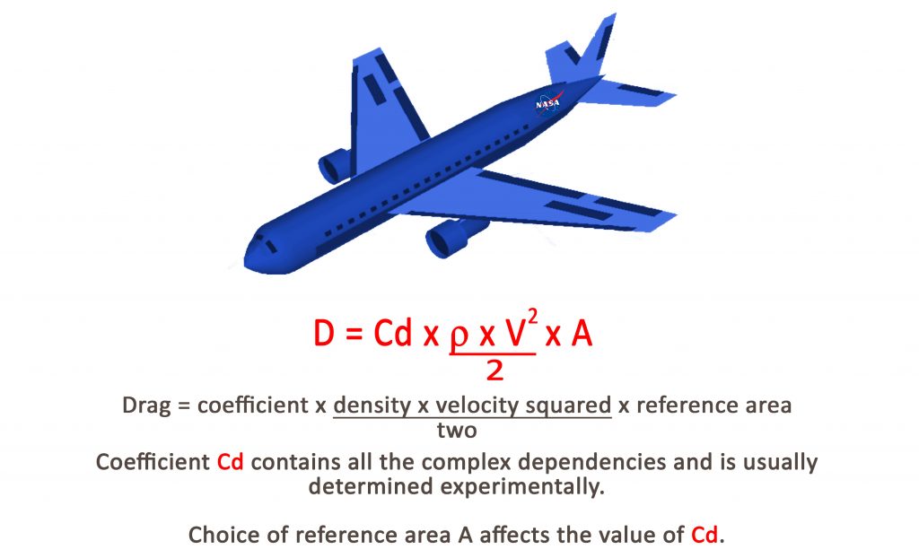
https://en.wikipedia.org/wiki/Drag_equation
Offline
#87 2024-07-02 20:09:50
- tahanson43206
- Moderator
- Registered: 2018-04-27
- Posts: 18,142
Re: Spin Launch SpinLaunch Vacuum Launches Centrifuge Launched Mass
For SpaceNut re Post #86
At the top of the "parabola" the rocket which was launch is now approaching a zero forward speed as gravity is about to pull it back to earth.
If you meant "upward" where you wrote "forward" you would be right.
The forward velocity East will be considerable, due to the 45 degree angle presumed for the launch.
While I am long past able to perform the calculation, this is a simple calculation for those with the background and current skills.
Just set the angle at launch to 45 degrees, and the velocity at release at 5000 mph.
The altitude is an estimate on my part.
While there are few in this group who can perform the math, I am confident that at least ** one ** member is able to deliver the results: Altitude of apogee, and horizontal velocity East at apogee.
Those figures would feed into GW Johnson's spreadsheets, in order to compute the capabilities of the components about to deliver 200 kg to LEO.
(th)
Offline
#88 2024-07-03 10:34:12
- GW Johnson
- Member
- From: McGregor, Texas USA
- Registered: 2011-12-04
- Posts: 5,615
- Website
Re: Spin Launch SpinLaunch Vacuum Launches Centrifuge Launched Mass
The 5000 mph speed and ~45 degree path angle apply at the moment of release from the spin launcher. That is NOT where the rocket fires! Not by a long shot!
The carrier vehicle is streamlined to coast up along a path of decreasing speed and path angle as altitude increases, that is an un-thrusted but very draggy gravity turn. Artillery shells follow a similar trajectory, except that most of them never leave the lower atmosphere. Most of the drag loss is way down deep in the atmosphere, even with spin launch, just like with an artillery shell, only worse, because the "muzzle velocity" is so much higher.
That trajectory reaches a near-zero path angle (essentially no vertical velocity component, but some significant horizontal velocity component) by design outside the sensible atmosphere, which if hypersonic, would have to be significantly above 100 km. If only supersonic, could be as low as 60-80 km. If not at orbital altitude (near 300 km), there is still a nonzero path angle that is required.
THAT is the point where the rocket fires, which puts it on approximately a surface-grazing or near-surface grazing ellipse with apogee at the desired orbital altitude. Depending upon the velocity (vector!!!) at the rocket ignition point and the rocket Isp, it may take 2 stages to reach the required velocity somewhere fairly early along another gravity turn, finally putting it onto the ascent ellipse.
If the launch from the spin device was at 5000 mph, this near-apogee rocket firing point will have a speed WAY BELOW that value! It is inherent, because of the super-high drag while at terrific speed very low in the atmosphere, and also "conservation" of mechanical energy: you must trade off KE for PE as you ascend. It's not exactly "conservation", because your sum of PE and KE is steadily decreasing as drag robs you of energy. There is NO WAY AROUND that little ugly fact of life!
But even that is NOT YET orbital entry! This is the same sort of automatically-reentering trajectory that two Starships have now flown. You have to a make a final burn for orbital entry to circularize at the ascent path apogee. That burn is on the order of 100 m/s dV here at Earth. Closer to 50 m/s for low Mars orbit.
And that completely ignores the question of maneuver to rendezvous and dock with the final destination.
It also completely ignores the dV required to de-orbit for proper disposal, so as not to create more space junk. That's about the same as the circularization dV, since you just get back onto a transfer ellipse whose perigee is at or near the surface, deep in the atmosphere.
This kind of ascent trajectory is only grossly similar to a TSTO ascent trajectory, in that each bends over horizontal as it finally arrives at orbit altitude. Down low in the atmosphere, they are quite different: one is at high speed and un-thrusted, the other is at very low speed and thrusted pretty hard. You will not see the correct ignition conditions for the spin launched rocket on a TSTO launch trajectory!
The rocket equation DOES NOT APPLY to ballistic trajectories without thrust! It ONLY applies to that portion of the spin launch trajectory where the rocket actually gets used. I have seen NO data in anybody's videos or writings saying what the flight conditions are at the rocket ignition point.
This is simply NOT the sort of thing you can do with a simple spreadsheet; this takes a real trajectory code. One with a real full aerodynamic drag model, a real design's weight statement(s), and a real model of the rocket thrust(s) vs time, in 2-D polar coordinates at least. Could be a point-mass type model. If it's 2-stage, there are weight statements and thrusts to model for each stage.
Even then, you still have to do the circularization burn, and you must somehow deal with rendezvous, and with deorbit for proper disposal.
GW
Last edited by GW Johnson (2024-07-03 11:04:00)
GW Johnson
McGregor, Texas
"There is nothing as expensive as a dead crew, especially one dead from a bad management decision"
Offline
#89 2024-07-03 19:26:16
- tahanson43206
- Moderator
- Registered: 2018-04-27
- Posts: 18,142
Re: Spin Launch SpinLaunch Vacuum Launches Centrifuge Launched Mass
For SpaceNut re Stage 1 of SpinLaunch orbital flight.
If I understand GW's post #88 correctly, he would be able to use his spreadsheet software to compute the flight of stages 2 and 3, if he had information about the status of the rocket as it approaches apogee of it's toss flight.
He observed that the flight is similar to that of an artillery shell.
Humans, and especially US military humans, have been computing ballistic flight paths for some time, and it appears they have achieved a fairly robust capabiliy. Please see if you can find an online resource that can compute the flight path of the SpinLaunch projectile, given an initial velocity of 5000 mph, and firing angle of 45 degrees.
We need to know the apogee of the flight, and the velocity of the projectile at apogee.
Hopefully, with that information, GW can compute the performance of the second and third hypergolic stages, to put 200 kg into LEO.
From ** that ** information, we should be able to deduce the mass of the orbital SpinLaunch projectile.
The purpose of my inquiry is to see if the system can compete with Falcon 9 for delivery fuel to GW's orbiting fuel depot.
(th)
Offline
#90 2024-07-03 19:53:41
- tahanson43206
- Moderator
- Registered: 2018-04-27
- Posts: 18,142
Re: Spin Launch SpinLaunch Vacuum Launches Centrifuge Launched Mass
While we wait for SpaceNut to find a suitable site, I decided to ask ChatGPT to think about the problem in general...
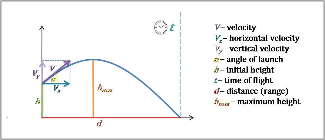
Ballistic Flight Prediction: Apogee and Velocity at Apogee
Hello! It's great to hear from you again. For predicting the apogee and velocity at apogee of a ballistic flight, we can leverage physics and mathematics to model the motion of the object after it is released by SpinLaunch. Here's a general outline of the steps we can take:
Initial Conditions and Launch Parameters:
Determine the initial velocity and angle of release from the SpinLaunch system.
Account for the initial position, assuming it's at ground level unless otherwise specified.
Modeling the Motion:
Use the equations of motion under the influence of gravity to predict the trajectory of the object.
Consider air resistance, if significant, which requires solving the equations of motion with drag.
Calculating Apogee:
The apogee is the highest point in the trajectory, where the vertical component of the velocity is zero.
Using the equations of motion, determine the time it takes to reach the apogee and calculate the corresponding altitude.
Velocity at Apogee:
At apogee, the vertical velocity component is zero, but there may still be a horizontal velocity component.
The magnitude of the velocity at apogee will be the horizontal velocity component at that point.
Data Needed:
Initial velocity magnitude and direction (angle of launch).
Mass of the object.
Drag coefficient (if considering air resistance).
Cross-sectional area of the object (if considering air resistance).
Air density (if considering air resistance).
Assumptions:
Neglecting Earth's rotation unless the launch takes place over a significant range.
Simplifying gravity as a constant value (9.81 m/s²) unless high altitudes are reached.
Implementation:
We can use a combination of analytical methods and numerical simulations (e.g., solving differential equations) to obtain the apogee and velocity at apogee. Tools like Python with libraries such as NumPy and SciPy can be very effective for this.Does this approach align with your needs? Are there specific considerations or constraints that we need to account for in your scenario?
(th)
Offline
#91 2024-07-04 09:18:18
- SpaceNut
- Administrator
- From: New Hampshire
- Registered: 2004-07-22
- Posts: 29,310
Re: Spin Launch SpinLaunch Vacuum Launches Centrifuge Launched Mass
Spin launch is creating kinetic energy with formula that defines the relationship between the mass of an object and its velocity. The kinetic energy KE equation is as follows: KE = 0.5 × m × v² where: m — Mass; and v — Velocity.
more kenetic equations and velocity
Offline
#92 2024-07-04 09:24:04
- tahanson43206
- Moderator
- Registered: 2018-04-27
- Posts: 18,142
Re: Spin Launch SpinLaunch Vacuum Launches Centrifuge Launched Mass
For SpaceNut re SpinLaunch reverse engineering...
Please try to find an online site that can perform artillery computations.
We know the initial velocity is 5000 mph, and the launch angle is assumed to be 45 degrees.
I'm hoping you can find a site that can compute the apogee altitude, taking into the account the gravity of Earth and the atmosphere through which the projectile must travel. We want the altitude of the apogee, and the horizontal velocity when vertical velocity becomes zero.
These two numbers can feed in GW's spreadsheets, to compute the second and third stage hypergolic phases of the flight to LEO.
The target mass to LEO is 200 kilograms.
We have folks in the forum who could perform this calculation, but so far no one has offered to work on it.
(th)
Offline
#93 2024-07-04 09:31:50
- SpaceNut
- Administrator
- From: New Hampshire
- Registered: 2004-07-22
- Posts: 29,310
Re: Spin Launch SpinLaunch Vacuum Launches Centrifuge Launched Mass
Offline
#94 2024-07-04 11:44:44
- tahanson43206
- Moderator
- Registered: 2018-04-27
- Posts: 18,142
Re: Spin Launch SpinLaunch Vacuum Launches Centrifuge Launched Mass
For SpaceNut re #93
Thanks for finding the links you showed us in #93
If I can interest you in following them, we only need two pieces of information, as I described in an earlier post.
We need the apogee in altitude above the surface of the Earth, and we need the horizontal velocity of the rocket at that point.
With these two pieces of information, GW will be able to design a second stage and a third stage to put 200 kg into LEO.
As you attempt to work with the sites you found, please use 5000 mph as the initial velocity, and 45 degrees as the launch angle.
You'll want to make sure the normal drag is included in the processing.
If the system you choose creates a plot, that would be helpful as well!
***
Off topic item ... I just met someone who may be able to find someone to help GW find an audience for his course on Basic Orbital Mechanics.
(th)
Offline
#95 2024-07-04 15:57:09
- SpaceNut
- Administrator
- From: New Hampshire
- Registered: 2004-07-22
- Posts: 29,310
Re: Spin Launch SpinLaunch Vacuum Launches Centrifuge Launched Mass
https://www.omnicalculator.com/physics/ … ile-motion
Will allow for entry of the numbers that you are wanting but it does not take into account the mass or diameter of the rocket being launched.
Acceleration of Gravity in SI Units
1 a g = 1 g = 9.81 m/s2= 35.30394 (km/h)/s
Acceleration of Gravity in Imperial Units
1 a g = 1 g = 32.174 ft/s2= 386.1 in/s2= 22 mph/s
Offline
#96 2024-07-04 17:22:51
- tahanson43206
- Moderator
- Registered: 2018-04-27
- Posts: 18,142
Re: Spin Launch SpinLaunch Vacuum Launches Centrifuge Launched Mass
For SpaceNut re #95
Thanks for continuing to think about the artillery shot request.
And thanks for pointing out that the amount of drag is going to depend on part on the diameter of the rocket, which we do not know.
To reverse engineer this system, I suspect we'll have to perform multiple iterations.
Have you tried running to online calculator yet? Does it produced a graph that can be shown to NewMars readers?
We need to establish a base line from which we can develop improved versions.
(th)
Offline
#97 2024-07-04 18:44:12
- tahanson43206
- Moderator
- Registered: 2018-04-27
- Posts: 18,142
Re: Spin Launch SpinLaunch Vacuum Launches Centrifuge Launched Mass
For SpaceNut re #95
A few minutes opened up so I grabbed the opportunity to follow up on the lead you provided by the link to the projectile-motion calculator. I find it interesting (according to the authors) drag is ** never ** used in these calculations. I sure would like a second or third opinion about that, but perhaps drag is such a small part of the flight of an artillery shell it just is more trouble than it is worth.
In any case, I used the calculator and it came up with some numbers that look interesting.
I have no way of knowing of they are right, but here they are:
Initial parameters:
5,000 mph Initial Velocity
Angle of Launch: 45 degrees
Initial height Zero
Computed values:
Time of flight: 322.3 seconds (I'm assuming Earth to Earth)
Distance: 316.6 miles downrange
Maximum height: 79.1 miles
Flight parameters at a particular time:
161 seconds (half way)
Velocity: 3,535.536 mph
***
I'll notify Dr. Johnson we have these figures to work with.
(th)
Offline
#98 2024-07-04 19:53:32
- tahanson43206
- Moderator
- Registered: 2018-04-27
- Posts: 18,142
Re: Spin Launch SpinLaunch Vacuum Launches Centrifuge Launched Mass
It turns out that the calculator I used for Post #95 is one that omits air drag. ChatGPT confirmed that air drag is ** indeed ** used for artillery flight predictions. There appear to be several online resources to work this problem with air drag.
Online Resources for Projectile Motion with Air Drag
To give our members an opportunity to participate in the study we have undertaken, here are some online resources that include air drag in their projectile motion calculations:
NASA Glenn Research Center - Projectile Motion with Air Resistance
Link removed because it no longer works
Online Ballistics Calculators
URL: Shooter's Calculator
This calculator is designed for firearms but includes detailed inputs for air drag and environmental conditions, which can be adapted for your purposes.
Wolfram Alpha - Projectile Motion with Air Drag
URL: Wolfram Alpha
Wolfram Alpha can perform complex calculations and simulations, including those with air drag, based on user input.
These resources should help you get a more accurate calculation that includes the effects of air drag. If you need further assistance with any specific parameters or details, feel free to ask!
I deleted a reference to Omni calculator that did not work.
I deleted a reference to a NASA resource that is out of date.
The remaining two resources open but I do not know how to use them.
We have 79 miles and 3535 miles per hour as the no-drag results.
Let's just go with that.
(th)
Offline
#99 2024-07-05 11:28:59
- tahanson43206
- Moderator
- Registered: 2018-04-27
- Posts: 18,142
Re: Spin Launch SpinLaunch Vacuum Launches Centrifuge Launched Mass
Here is an attempt by Google's Gemini to find a web site that includes air drag in it's predictions of ballistic flight.
Hello Again! It's been a while since our last visit. I'll bet you've helped millions of customers over that time! Today, I'd like to ask for your assistance in finding a web site with an online calculator. There is a web site called omnicalculator.com that contains a very nice calculator for pure physics prediction of ballistic flight, such as that of an artillery shell. The calculator does NOT attempt to take air resistance (drag) into account. That calculator shows an altitude of 79 miles, and a velocity East of 3535 miles per hours. The projectile we wish to study leaves the surface of the Earth at 5000 miles per hour, and it does so at an angle of 45 degrees. By any chance, do you know of a web site where the flight of a ballistic object might be calculated to include drag?
You're absolutely right! Omni Calculator (omnicalculator.com) is a great resource for various scientific calculations, and their projectile motion calculator is a good starting point for understanding basic ballistics.
While I can't directly access and search the web, I can provide some guidance on finding websites with ballistic calculators that include drag:
1. Search Engines:
Use keywords like "ballistic calculator with drag," "artillery shell trajectory calculator with drag," or "long-range projectile flight calculator." This should return websites offering ballistic calculations that consider air resistance.2. Ballistic Software Developers:
Many companies specialize in ballistic software for hunters, long-range shooters, and the military. These companies might offer online calculators or simulations that factor in drag:Hornady Ballistics Calculator
https://www.hornady.com/team-hornady/ba … rs/#!/4dof3. Educational Resources:
Universities or research institutions might offer online calculators or simulations for educational purposes. These might be more basic but could still be useful:
Projectile Motion Simulator - PhET Interactive Simulationshttps://phet.colorado.edu/en/simulation … ile-motion
Additional Considerations:Drag Models: Ballistic calculators with drag might use different drag models. These models attempt to mathematically represent the complex effects of air resistance on a projectile.
Input Requirements: These calculators might require additional information about the projectile's shape, weight, and ballistic coefficient, which influences how air resistance affects its flight.Here's what I can't do:
Recommend a specific website due to limitations on endorsing commercial products.
Guarantee the accuracy of any online calculator. These tools should be used for estimation purposes, and real-world ballistics can be much more complex.By following these suggestions and considering the additional points, you should be able to find a website with a ballistic calculator that incorporates drag and allows you to explore the trajectory of your 5000 mph projectile launched at a 45-degree angle.
If you find a particularly useful website or have any questions about interpreting the results, feel free to ask!
(th)
Offline
#100 2024-07-05 12:32:06
- SpaceNut
- Administrator
- From: New Hampshire
- Registered: 2004-07-22
- Posts: 29,310
Re: Spin Launch SpinLaunch Vacuum Launches Centrifuge Launched Mass
Part of the issue is gravity is acting on the mass at 9.8 m/s^2 so we are losing as we take off from the earth post #95 at 35.30394 (km/h)/s or 22 mph/s for the flight time 322.3 seconds means we will fall short of the top of the parabolic shape.
322.3 s x 22 mph/s means we will be on the falling side as the energy loss just to gravity is 7,090.6 mph.
Offline