New Mars Forums
You are not logged in.
- Topics: Active | Unanswered
Announcement
#76 2022-01-02 12:49:32
- SpaceNut
- Administrator
- From: New Hampshire
- Registered: 2004-07-22
- Posts: 30,818
Re: A More Practical Interplanetary Colonization Ship
GW it has similarities to ION drive without the mass of fuel, or power systems on the main rockets habitat area as it places the ions off that ship and makes a power satellite where the energy is coming from. The ships engine is a reflector of the pulsed beam at a coil to direct that force into an exhaust engine plumb to make propulsion for the ship.
Offline
Like button can go here
#77 2022-01-02 13:23:02
- tahanson43206
- Moderator
- Registered: 2018-04-27
- Posts: 25,268
Re: A More Practical Interplanetary Colonization Ship
For SpaceNut re Post #74
The magnetic force needs multiple turns under a high voltage low current design to create the field
Amp * turns = one Gauss (B) is equal to one Oersted (H) in air.So a rigid 1 turn needs high amperage to create the same field strength.
There are many more equations to solve for the values but the concept of the field is to bring the diffused received plasma into focus for thrust out of the engine after reflection.
The magnetic field can be created in the shape of a funnel by placing larger diameter rings at different distances from each other.
There are two aspects to the discussion.
One is generation of a flow of ions ... I think the technology to do that is fairly well understood.
My question has still not been answered, and I suspect there ** is ** no answer ...
The receiving vessel needs an apparatus to intercept a flood of charged particles.
No one in this forum has (to the best of my knowledge) published any hint of how that might be done.
The ** only ** reference I have found so far is the Wikipedia write-up on the work of Zubrin and others, to imagine a way to capture the momentum of charged particles to slow a rapidly moving spacecraft as it approaches a planetary body that has a surrounding of orbiting charged particles.
That device (as I understood it) consisted of a single strand of wire, unspooled from a spacecraft and given a current to generate a magnetic field.
The Wikipedia article asserted that the wire would tend to straighten out into a circle due to the magnetic field generated by the current.
The effective force that might be generated (as I understood the article) would be measured in grams. The thin wire would be connected to the payload/spacecraft, and as the particles interacted with the wire, force would be conveyed along the wire to the payload.
Naturally, the momentum of the payload would act to deform the circle of wire, which would stretch into the form of a paper clip.
If someone with write access in the forum knows of a link to an article that clarifies this question, I'd like to see it.
To the best of my knowledge, no such experiment has been performed in space, but my knowledge is limited so someone may be able to find an example, and hopefully a scientific paper reporting on the results.
Edit: If a reader would like to contribute, and is not currently a member, please check the Recruiting topic for contact procedure.
(th)
Offline
Like button can go here
#78 2022-01-02 17:14:53
- kbd512
- Administrator
- Registered: 2015-01-02
- Posts: 8,533
Re: A More Practical Interplanetary Colonization Ship
tahanson43206,
No hint of how you would create an electromagnetic field for the ions to react off of?
I'm not sure I understand what you're getting at.
We're talking about the same electromagnetic nozzle technology that makes VASIMR work.
These experiments have been performed in vacuum chambers numerous times, over the course of decades.
MagBeam uses electromagnets on both ends to complete an electric circuit through which a plasma flows and is reacted off of the receiving spacecraft / powered ship to produce thrust.
Offline
Like button can go here
#79 2022-01-02 17:30:32
- Calliban
- Member
- From: Northern England, UK
- Registered: 2019-08-18
- Posts: 4,339
Re: A More Practical Interplanetary Colonization Ship
Any magnetic field will change the trajectory of charged particles. And F = m x dV. Velocity is a vector quantity, so changing the direction of motion changes the vector and generates a net force, even if speed does not change. You can calculate the force per unit area of the magnetic field, as a function of flux entering the area, multiplied by the velocity change, which is a function of local B. Integrate that across the entire beam width and you get total force.
"Plan and prepare for every possibility, and you will never act. It is nobler to have courage as we stumble into half the things we fear than to analyse every possible obstacle and begin nothing. Great things are achieved by embracing great dangers."
Offline
Like button can go here
#80 2022-01-02 17:35:05
- SpaceNut
- Administrator
- From: New Hampshire
- Registered: 2004-07-22
- Posts: 30,818
Re: A More Practical Interplanetary Colonization Ship
The receiver is a parabolic dish that reflects back a common beam...which the magnetic s control that beam after it gets beyond the focal point
https://en.wikipedia.org/wiki/Parabolic_reflector
this is similar to what we are doing with satellite TV dish.
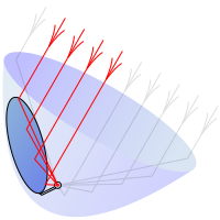
The red is the incoming and the bounce is in gray to the feed horn which is replaced with the magnetic funnel.
Offline
Like button can go here
#81 2022-01-03 11:35:44
- tahanson43206
- Moderator
- Registered: 2018-04-27
- Posts: 25,268
Re: A More Practical Interplanetary Colonization Ship
For SpaceNut re #80
Thanks for showing what the receiver system on a vessel boosted by a stream of charged particles might look like.
To this point, the sponsor of this topic has not shown us what system ** he ** thinks is needed. Whatever system is designed must transfer tons of force to a space craft in a short amount of time. To my knowledge (limited as it is) there exists in the Universe NO SUCH SYSTEM. The idea is (at this point) (to the best of my knowledge) purely a conjecture based upon a paper napkin sketch.
Last night, in the zoom meeting, we did make some progress. We discussed tiny examples of plasma manipulation. An electron microscope was mentioned. It occurred to me that good old fashioned vacuum tubes were examples of devices that manipulated charged particles, and entire industries were build upon the principles on which those devices were based.
The idea of using charged particles to accomplish something useful has merit. As was pointed out in the meeting, fusion devices will (when successful) manage flows of plasma for delivery of useful energy and in some cases, useful force.
In the meantime, any talk of delivering more than one or two grams of force to a moving space craft from another moving space craft is not just speculation based upon a paper napkin sketch ... it is ** wild ** speculation, based upon a blob of ketchup on a napkin.
We ** did ** make one small bit of progress last night .... it was agreed that the satellite that is going to send a powerful flood of charged particles toward a waiting receiving space vessel MUST send exactly the same amount of force precisely backward in order to maintain it's movement in a stable orbit.
Management of that backward flood of charged particles is going to be interesting. Any space satellite, such as the Chinese space station, needs to be well away from both the forward beam and the backward beam. If ** any ** space craft belonging to another Nation is at risk of damage due to a beam in either direction, the beam cannot be fired, and the boost opportunity will pass.
In contrast, a flood of particles from a Lunar projector would NOT need to be balanced by an equal backward force, because the mass of the Moon is sufficient to absorb the backward force.
The problem of dispersion of charged particles due to repulsion due to identical electric charge has NOT been adequately addressed.
A possible solution is to send an equal number of positively charged ions and negatively charged ones, so that they are attracted to each other in flight, and become neutrally charged particles headed to the destination.
The destination had better be equipped to handle a flow of rapidly moving particles, and a magnetic field would NOT do the job if the particles have no charge.
(th)
Offline
Like button can go here
#82 2022-01-03 14:02:45
- kbd512
- Administrator
- Registered: 2015-01-02
- Posts: 8,533
Re: A More Practical Interplanetary Colonization Ship
tahanson43206,
From the article:
A magnetic mirror, known as a magnetic trap (магнитный захват) in Russia and briefly as a pyrotron in the US, is a type of magnetic confinement device used in fusion power to trap high temperature plasma using magnetic fields. The mirror was one of the earliest major approaches to fusion power, along with the stellarator and z-pinch machines.
In a classic magnetic mirror, a configuration of electromagnets is used to create an area with an increasing density of magnetic field lines at either end of the confinement area. Particles approaching the ends experience an increasing force that eventually causes them to reverse direction and return to the confinement area.[1] This mirror effect will only occur for particles within a limited range of velocities and angles of approach, those outside the limits will escape, making mirrors inherently "leaky".
Charged Particle Flow in Magnetic Bottles
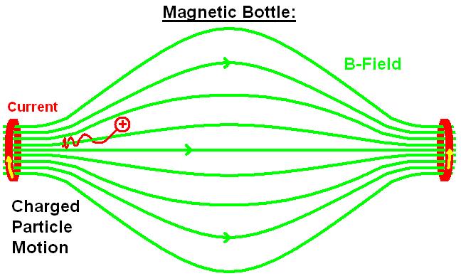
Q-Cumber Magnetic Mirror, circa 1955:

Chop off one end of that "magnetic bottle". Now you have a "magnetic mirror" that you can fire a magnetized beam of plasma at.
Every Tokamak in existence uses magnetic mirrors, except that they use multiple mirrors because they're trying to confine a plasma, rather than simply bounce a plasma beam off one end of a device.
Offline
Like button can go here
#83 2022-01-03 20:36:49
- SpaceNut
- Administrator
- From: New Hampshire
- Registered: 2004-07-22
- Posts: 30,818
Re: A More Practical Interplanetary Colonization Ship
As much as the beam will be speeding up the ship the satellites are going to be slowing down just as much from each pulse that is beamed to the ships engine system. Space has this weird thing about equal and opposite reactions to thrust for rockets and things in motion.
Offline
Like button can go here
#84 2022-01-04 09:34:23
- tahanson43206
- Moderator
- Registered: 2018-04-27
- Posts: 25,268
Re: A More Practical Interplanetary Colonization Ship
For SpaceNut re #83
I think Sir Isaac Newton would be pleased with the way you have updated his Laws of Motion for the present day, and for the modern audience of this forum.
He published [The Principia] in 1687 (according to the preface) and your translation appeared in 2022, 335 years later.
For the readers of this forum who may not be familiar with Sir Isaac's writings, here is what he wrote:
In Axioms, or Laws of Motion
Law III.
To every action there is always opposed an equal reaction: or the mutual actions of two bodies upon each other are always equal, and directed to contrary parts.
The ideas of kbd512, to provide impulse to a space craft leaving Earth Orbit using a transfer of momentum from a source satellite to a target satellite, seem well worth supporting, in hopes that kbd512 will develop them into a working system concept that can be successfully implemented by people on Earth, living today.
The idea of using electromagnetic energy has been studied and described at some length. For example (one of many) Dr. Robert Forward proposed using laser light to send a spacecraft to a distant star using laser light.
I'd like to take this opportunity to remember Dr. Forward, who was a wonderful public speaker as well as author of both fiction and non-fiction.
Per Google:
The Science and Fiction of Robert L. Forward
www.sciencedirect.com › science › article › pii › pdf
Later he studied space transportation technologies, including photon propelled sails, antimatter rockets and long tethers. Incidentally, gravitation and space.
Robert L. Forward - Wikipedia
en.wikipedia.org › wiki › Robert_L._Forward
He worked on such projects as space tethers and space fountains, solar sails (including Starwisp), antimatter propulsion, and other spacecraft propulsion ...
Robert L. Forward papers - Online Archive of California
oac.cdlib.org › findaid › ark: › entire_text
"Robert L. Forward, a science fiction writer, physicist and inventor whose ... on the technical details of space flight and other scientific issues that he ...
Robert L. Forward, 70, Physicist and Novelist - The New York Times
www.nytimes.com › 2002/09/28 › books › robert-l-forward-70-physicist-a...
Sep 28, 2002 · Robert L Forward, science fiction writer, physicist and inventor ... on the technical details of space flight and other scientific issues ...
Robert Forward | The Planetary Society
www.planetary.org › profiles › robert-forward
He worked on such projects as space tethers and space fountains, solar sails (including Starwisp), antimatter propulsion, and other spacecraft propulsion ...
The suggestion of kbd512 is to use particles having mass to transfer momentum from a source satellite to a target satellite.
The particular suggestion under discussion recently was to accelerate particles by ionizing them so they respond to a magnetic field.
To accelerate a space vessel of hundreds of tons mass, a correspondingly large momentum transfer is required.
The "traditional" way of achieving this result is to release stored chemical energy to impart momentum to molecules from the stern of a space craft.
An alternative, as suggested by kbd512, is to impart energy to a mass of particles of sufficient magnitude to cause a transfer of momentum to the target vessel.
To the extent this topic invites input of knowledge on how to do this, we will all benefit.
Sir Isaac would surely be proud to see how his ideas have been translated into the modern age.
(th)
Offline
Like button can go here
#85 2022-01-04 14:14:57
- kbd512
- Administrator
- Registered: 2015-01-02
- Posts: 8,533
Re: A More Practical Interplanetary Colonization Ship
tahanson43206,
Thank you for forcing me to think about how to best answer your question in a simple way. It's an actual / real problem, but nowhere near as severe as you think. I had to go back to some basic physics texts to understand what's going on here. Sir Isaac Newton's over-simplified explanation of reaction to imparted force may be sufficient for explaining billiard balls to school children, but not sufficient to explain the physics behind these advanced propulsion concepts. I've been pondering over this explanation since our last meeting, because it receives so little attention in the texts of such proposals. I think the authors of these proposals presume an understanding of physics that most people, including myself, don't have off the top of their heads, even though I intuitively knew that your assertion is wrong.
MagBeam is one of many such proposals, and you mentioned laser propulsion as another. While lasers do "recoil" in space, that recoil force is tiny compared to the pressure of the photons reacting off of a light sail. In the MagBeam concept, a good portion of the particle acceleration takes place within the plasma channel, but far away from the Helicon's exit nozzle aboard the MagBeam station. The plasma channel is a purely electromagnetic "rail gun" that does not use physical components for most of the acceleration rail. In other words, the particles continue to accelerate so long as they're confined within the particle beam, as the beam propagates away from the Helicon. Continued confinement and imparting of energy as part of the electromagnetic circuit occurs while the particles themselves are not physically reacting off of the electromagnet that both heats the gas to plasma energies and expels it from the nozzle of the MagBeam's helicon.
I was in the military, so we're going to use guns as our example of why "for every action, there's an equal and opposite reaction" is grossly oversimplified. As Dr Richard Feynman would say, it's suitable for explaining "why" to people with no basic understanding of physics, but not suitable for physicists designing plasma rockets. So, let's provide a concrete example of how wrong such an oversimplification truly is.
The free recoil energy of a 35 pound (loaded weight) Barrett M82 .50 BMG rifle, is 97 foot-pounds (about the same as the muzzle energy of a projectile fired from a high powered pellet gun). The 800 grain Barnes slug that it fires at 2,895 feet per second from this rifle carries 14,895 foot-pounds of energy with it. If all 7 tons of force was imparted to the shooter, that is more than enough to knock absolutely anyone off their feet, but all 7 tons of force is only transferred to the target when the target is dense and hard enough to stop that slug cold, and nearly all of that energy would be dissipated as heat, which is why holes in armor plates appear as though the slug that struck it literally "melted" its way through the armor, because that's exactly what happened. So, why doesn't the man or woman shooting the .50 BMG go flying backwards? Well, the recoil force is obviously not equal to the force that the slug can impart to the target when the target stops it cold. The relative mass of the slug and target and rifle / shooter combo also matter greatly here. Double the weight of the M82 and the free recoil force generated goes down by a lot. None of that takes away from the simple fact that that little slug of metal is indeed carrying 7 tons of force with it, and the shooter and rifle combined don't have a mass anywhere near enough to counteract that much force while remaining upright. If there was indeed an "equal and opposite reaction", then the shooter would be knocked flat, yet you can fire one of those rifles while standing straight up, if you have enough upper body strength. There are also a few brave souls who fire them without their muzzle brakes attached "for science", and while it leaves a nice bruise on their shoulder, they weren't knocked down and their collar bones weren't broken, either. So... The muzzle energy of that tiny projectile is roughly 153 TIMES the free recoil energy generated during firing. Benchrest .50 BMG shooters who fire their guns with no recoil mitigating devices of any kind are still not knocked flat. If there was indeed an "equal and opposite reaction", then they would have to be leveled by each shot, but they're not, and many of these well-funded shooters fire dozens of rounds per range session.
Many a red neck has "discovered" that 2X4s or even welded angle irons are woefully insufficient to withstand the kinetic force generated by firing a .50 BMG fired at a 1" to 2" thick steel plate target, and that the shock will often break welds. Well, no duh, Sherlock! 7 TONS OF FORCE! The energy carried by that .50BMG 800 grain (51.84 grams) Barnes slug fired at 2,895 feet per second is equivalent to being struck by a 2,000 pound car moving at 14.9mph. Would a Smart Car knock your target flat? Easily. Well, guess what? The bullet does the same thing when that block of steel stops it cold. The car only carries slightly less energy than the slug at that speed and weight (14,843 foot-pounds for the car vs 14,895 foot pounds for the supersonic slug of metal). Now we know why car accidents at highway speeds are so devastating. At 70mph, that same car is carrying 327,607 foot-pounds of energy with it. That .50 caliber bullet would have to be moving at 9,260mph to generate equivalent energy. However, we can see the disproportionate effect speed has on the kinetic energy of tiny objects.
Would it make any difference if you fired that Barrett in a vacuum? Nope. The free recoil force remains the same, the muzzle energy of the projectile remains the same or slightly increases because there's no air resistance. If the bullet struck a target downrange, then it would still impart roughly 7 tons of force. Would you still have to counteract the recoil force generated? Obviously. Is 100 foot-pounds anywhere near 15,000 foot-pounds. Obviously not.
We're talking about expelling milligrams to a gram or so of propellant per second from a station that weighs 75,000kg. The drag force generated by the solar arrays in the tenuous but still present atmosphere in LEO is more significant. Most of the plasma acceleration is from heating and the propagation that occurs along the channel. The plasma is entrained / confined within an electromagnetic wave, and the wave does the accelerating of the trapped particles (Hydrogen ions). When the ions smack into the magnetic lens of the much slower ship, then you have very significant transfer of force, same as you would by firing a Barrett or .50 caliber machine gun at a thick steel plate in space. No, I'm not advocating for the ".50BMG propulsion system", just sayin.
Now that this idea has been put out to pasture using a very simple real world example, what's the next question about the concept?
Offline
Like button can go here
#86 2022-01-04 15:50:10
- GW Johnson
- Member
- From: McGregor, Texas USA
- Registered: 2011-12-04
- Posts: 6,242
- Website
Re: A More Practical Interplanetary Colonization Ship
The Soviet "Almaz" manned spy satellite flew under the name Salyut, each time as one of the early Salyut missions. It was armed with a 23 mm cannon for "self defense". I think there were 3 of the Salyuts that really were this Almaz station. The last one they test fired the gun in space, after the crew left. It shook the holy hell out of the station. That's a big gun, though.
GW
GW Johnson
McGregor, Texas
"There is nothing as expensive as a dead crew, especially one dead from a bad management decision"
Offline
Like button can go here
#87 2022-01-04 15:54:03
- kbd512
- Administrator
- Registered: 2015-01-02
- Posts: 8,533
Re: A More Practical Interplanetary Colonization Ship
Response to RobertDyck moved by request of tahanson43206:
Robert,
As promised during the Zoom call, here's a video of one such "area denial device" installed into the corridor of a building, similar to that "Red Queen" scene from the Resident Evil movie starring Milla Jovovich where the "laser beams" slice everyone (except Milla, of course- couldn't kill off the protagonist) to pieces inside the corridor:
You can find research papers, other demonstration videos, and explanations of the device, including a Wikipedia article.
The US Army first started working on this technology 10 or 15 years ago. Instead of zapping people, the latest incarnation of the technology produces a visual and audible effect similar to a stun grenade. While it could easily be used to injure or kill people through electrocution, the US Army has been looking for ways to capture or disperse crowds of people or shut down motor vehicles without killing them. It now views the technology as a cheaper / more effective version of a "flash-bang" grenade that's less dangerous than pyrotechnic devices. In any event, the military uses firearms and explosives to kill people, not stun guns, because firearms work no matter what a person happens to be wearing. Weapons like this "plasma stun gun" may not work very well or at all if the person was wearing a space suit, for example.
They do have an Apache gunship mounted high power laser pod that was used to kill terrorists in Afghanistan, but again, not guaranteed to work under all atmospheric conditions, whereas the explosive shells fired from the Apache's 30mm chain gun generally chew up anything. If that doesn't work, it has 70mm rockets with warheads equivalent to a small artillery shell and AGM-114 Hellfire anti-tank missiles. In general, the actual users see weapons like this as expensive toys, maybe nice to have under specific conditions, but not a suitable replacement for the existing weapons.
A handful of our surface combatant ships are fitted with laser-based point defense systems (SEQ-3 / LAWS) as well, but again, sailors trust RAM missiles (a surface-to-air point defense weapon based upon the AIM-9 Sidewinder) and depleted Uranium slugs fired at 6,000 rounds per minute. The lasers can easily fry small drones / drone-based weapons and work quite well for that purpose, but are not considered to be suitable replacements for slugs of heavy metal. Even if it had 10X more power than it already does (1MW vs 100kW), it would not replace 20mm CIWS. No amount of "whiz bang" will replace current systems for the foreseeable future. You'd have to attain 100MW+ energy levels before you see substantial replacement of existing weapon systems.
The gun barrel life of the rail guns is so low that, despite the fact that the system now attains the target velocity and fits within the specified space constraints, it would cost so much in operational costs to field that it's not deemed worthy of operational deployment. I don't know how you prevent Aluminum plasma from plating out on the gun barrel or eroding the surface, nor does anyone else, apparently, which is why these new weapons of war remain science fiction. The Chinese no doubt discovered the practical limitations of rail gun technology as well since they built a single prototype for testing and then shelved the idea. The most important advantages were supposed to be kinetic energy kills from hyper-velocity and longer range, but if you fire at a velocity the gun barrels can survive for the minimum specified service life, then you remove both advantages and are better off with conventional cannons. They could be cheaper alternatives to ground-based nuclear warhead interceptor missiles, but that's about it. The barrels are good for maybe 100 shots. Conventional cannon barrels have service lives measured in thousands of shots.
Offline
Like button can go here
#88 2022-01-04 17:00:26
- kbd512
- Administrator
- Registered: 2015-01-02
- Posts: 8,533
Re: A More Practical Interplanetary Colonization Ship
GW,
I'm aware of the Soviet "aircraft cannon test" aboard their military space station. I don't know if the quoted mass figure is correct, but a 37 pound 23mm cannon is most impressive, no matter how long it lasts. 37kg is more believable, given that the aircraft mounted variant weighed 58.5kg. Removing 20kg of weight from that weapon would be a feat in and of itself.
My overriding point was that the simplistic explanation of "equal and opposite force" is clearly very misleading and no advanced understanding of physics is required to "know that". The recoil force generated by firing a gun is clearly nowhere near as powerful as the kinetic energy carried by the projectile it fired when it slams into something and stops cold.
Edit: "Slams into something moving at a much lower relative velocity."
At first, I was going to post a very technical explanation, but I realized that if they don't know about the difference between the kinetic energy from firearm recoil and the kinetic energy imparted to a bullet, then a "down in the weeds" answer would be unlikely to convince them of their error. Recall that tahanson43206 had never heard of a magnetic mirror, despite the fact that we were using those in plasma physics experiments since y'all were kids. It's a torus of electrical steel or Iron with a Copper wire coiled around it. That's a "magnetic mirror" when you fire a beam of magnetized and charged particles at it. The particles are moving much much faster than the vehicle it's being fired at, so there's a significant disparity in force imparted. I know that seems incredibly simple, because it is.
So, imagine you're moving at 1,000m/s and a bullet starts overtaking you from behind at 1,001m/s. The difference in velocity is only 1m/s. The bullet can still hurt you if it hits you, but the actual force imparted is very low unless the bullet is really heavy. That bullet still carries the same amount of kinetic force with it, because it's moving at 1,001m/s, but the force it can impart to an object already moving at 1,000m/s is much lower. That is precisely why you require infinite force / infinite fuel (infinite kinetic energy) as you approach the speed of light. Each bit of matter you eject out the back of your rocket, even if that matter is moving at the speed of light (photons), imparts less and less kinetic energy (so you need more and more of it to continue to accelerate), on account of the speed of the craft that ejected it. Even at much lower relative speeds, the total kinetic energy imparted is still important, but in things like chemical rockets the force created by the hot expanding gas is reacted off the mass of the vehicle that the rocket engine nozzle is attached to, as you are already well aware, which is why a rocket in space can still accelerate to speeds faster than the engine's exhaust velocity (it's just not very efficient).
This same phenomenon is happening in the MagBeam, but this is so far outside of their wheelhouse that they don't understand it. Lots of people may claim to, but it's obvious that they don't. The ions don't instantly carry 100% of the kinetic energy imparted from the moment they leave the nozzle, which is different from what happens in a prototypical ion engine. In MagBeam, over the distance that the beam is projected, the confined ions accelerate to low 100s of kilometers per second, and then they slam into an object moving at 8km/s to 11km/s. So, what are they actually "reacting off of" when they accelerate down the plasma channel? Well, mostly each other and the electromagnetic field confining them. Is an ion that starts at 10km/s and eventually accelerates to 100km/s over the course of 1,000m actually imparting a lot of force to the MagBeam station? Obviously not, but again, some understanding of how the concept actually works is required.
Edit #2:
One other concept that many not be readily apparent if the reader doesn't understand what a Helicon is or how it works, is that the motion of the charged particles is helical (corkscrew shaped), meaning "not in a straight line". The plasma is still moving at a good clip, but it's not "directly out the back of the magnetic nozzle". The magnetic field continues to accelerate them long after they've left the nozzle, but it also confines them so that they don't scatter immediately after leaving the nozzle. So... These particles are still moving at high velocity, and then they encounter a magnetic and possibly electrostatic wall (if the powered ship also has a much smaller supply of gas to ionize and inject into the field generated by its magnetic mirror; this was an optional extra that was presented by Dr Winglee as a way to generate even more thrust). We're essentially firing atomic plasma "bullets" at a "slab of steel". Which vehicle has a lot more force imparted to it? Is it the vehicle firing "the gun", or the vehicle that the gun's "target" has been affixed to? We already exactly know how the gun example works and which part is generating the most kinetic energy by a good wide margin.
I also mulled over the idea of using a fire hose or a flame thrower shot that has not been ignited in order to explain the same effect, but figured that the firearm example was best for illustrating the vast disparity in the amount of recoil force and projectile kinetic energy. That said, fire hoses and flame throwers illustrate the exact same effect when expelling a stream of fluid, which is precisely what the ejected gas from the Helicon nozzle happens to be (ignoring the much higher energy state of the fluid and the much lower relative mass).
I've merely sent them back to the drawing board so that they can formulate a better question or move on to their next point. I have mentioned an actual problem, which is the drag force generated by the huge 4MW solar array in LEO. It's curious that nobody has asked about that, because that causes an actual problem for ISS with its much smaller solar arrays.
Last edited by kbd512 (2022-01-04 17:28:16)
Offline
Like button can go here
#89 2022-01-12 22:17:42
- kbd512
- Administrator
- Registered: 2015-01-02
- Posts: 8,533
Re: A More Practical Interplanetary Colonization Ship
There have been a series of assertions made about bearings of various types "not solving" the issue of accommodating counter-rotation style artificial gravity used by this large ship concept. That issue has been addressed in another thread and it has been demonstrated that various bearing mechanisms exist that can adequately support the considerable forces involved with counter-rotating of very heavy habitation rings, for purposes of supplying 1g of artificial gravity.
However, if what was meant by such posts was that an adequate engineering analysis has not been done to assert with confidence that some specific bearing design or type can address the requirements, then that statement would be accurate.
Although the proposed fluid bearings would be substantially lighter than ball / roller / wire type slew ring bearings, we will demonstrate here that suitable bearings of this commonly used type do exist and can be commercially purchased from America, Europe, or China.
We will use this document supplied by the Rotek Incorporated / Rothe Erde, a division of Thyssen-Krupp Technologies:
Rotek Incorporated - Large-Diameter Anti-Friction Slewing Rings
I live in America and Rotek bearings are Made in USA / Canada / Mexico, so we will use their product line and engineering calculations specified in the above document as our baseline design for a suitable set of 4 slew ring bearings intended to enable counter-rotation of the inflatable habitat modules.
The engineering portion of the document begins on Page 12.
To compute the parameters required to select a suitable product or have one custom-built, we will need to work through the following design criteria:
1. Load Transmission (how is the load from the habitation ring being transmitted through the center barrel section and slewing rings)
2. Slew Ring Loads (loads imparted by the attached habitation rings)
3. Bearing Raceway Capacity (loads imparted by the attached habitation rings)
4. Service Factors (design service life, acceptable wear rates, etc)
5. Bolt Capacity (fasteners that affix the slewing rings to the center barrel sections)
6. Turning Torque Capacity (how much driving force is imparted by the drive motors)
7. Gearing Configuration and Capacity (to counter-rotate the habitation rings)
8. Attached Structures Load Carrying Capacity (the center barrel sections)
9. Operating Conditions (-250F/+250F; hard vacuum; atypical for these mechanisms and requires specific types of steel, as well as matching of coefficients of thermal expansion to account for the out-of-round condition that will occur when part of the vehicle and slewing ring is differentially heated / cooled based upon exposure to direct sunlight or shadowing caused by the habitation ring(s) or vehicle orientation relative to the Sun)
Offline
Like button can go here
#90 2022-01-12 23:30:48
- kbd512
- Administrator
- Registered: 2015-01-02
- Posts: 8,533
Re: A More Practical Interplanetary Colonization Ship
To design anything by hand, I have to start with a series of assumptions about mass distribution within the habitation rings.
I am arbitrarily using my habitation ring sizing for a complement of 500, rather than 1,000, because even for a habitable volume suitable for 500 crew, it's functionally impossible to provide 20cm of water radiation shielding over the entirety of the habitation ring surface area using 250t of water. Therefore, my initial habitation ring dimensions are derived from the last set of dimensions shown in my Post #35 in this thread. A per-ship head count of 500 also happens to be near the limit of what a single Starship could seat if all of its interior decks were converted to a high density seating arrangement similar to a commercial airliner of equivalent volume, namely the Airbus A380.
25m: inner radius
30.5m: outer radius
2.75m: tube radius (almost identical to a Boeing 787 fuselage)
27.75m: radius of revolution
4,142.5m^3: volume of torus
8,285m^3: total pressurized volume (54X Boeing 787 cabin volume)
16.57m^3: total pressurized volume per person with 500 crew members
7,350m^3: total pressurized volume minus consumables volume (48X Boeing 787 cabin volume)
14.7m^3: total pressurized volume per person with 500 crew members after subtracting consumables volume
31,068.75kg: Hull mass per habitation ring
62,137.5kg: Total habitation ring mass
5,510kg: Total atmospheric mass at 8psi
Despite the inaccuracy, for ease of calculation of the forces generated, an assumption will be made that the mass within the habitation ring is centered upon the radius of revolution (27.75m). The force generated by asymmetric habitation ring loading will be calculated later.
Habitation Ring Design Assumptions:
1. Radius of revolution: 27.75m; Tube diameter: 2.75m
2. Each person carried aboard, and their personal belongings, accounts for 100kg of payload. Given a roughly 50/50 split between heavier men and lighter women, this seems reasonable.
3. Each habitation ring is 31t, is filled with 125t of water, 106.25t of food, and 25t for the colonists.
4. The habitation rings are connected to the center barrel section using inflatable "spokes" weighing 7.5t each / 22.5t in total.
5. Interior compartmentalization adds another 10t of mass per habitation ring.
6. Atmospheric mass accounts for 2.25t per habitation ring.
7. Each habitation ring therefore weighs 322t / 322,000kg / 709,888lbs.
8. We will arbitrarily apply a "mass growth factor" of 28t to bring our final habitation ring mass to 350t / 350,000kg / 771,618lbs. At 1g acceleration, this is approximately equal to the weight of a Boeing 747-200B at max takeoff weight, tugging on the center barrel section and slewing ring bearings.
With our habitation ring mass set at 350t, we will begin the sizing exercise for the center barrel sections and slewing ring bearing assemblies. There will be 4 such bearings per ship, 2 per habitation ring. For simplicity's sake, the center bearing will not be shared between the two habitation rings.
Offline
Like button can go here
#91 2022-01-13 08:00:24
- tahanson43206
- Moderator
- Registered: 2018-04-27
- Posts: 25,268
Re: A More Practical Interplanetary Colonization Ship
For kbd512 re topic development ...
First, thank you for responding with your usual thoroughness to the opportunity at hand...
Please consider updating the lead post in the topic with decisions as you make them.
I am attempting to collect decisions made by RobertDyck in Large Ship but they are scattered over hundreds of posts (1,059 to be exact)
I'd like to offer a suggestion.... Your habitat ring is designed for 500 people, but you need two of them.
Have I missed something? The sum should be 1,000, which is close to the size I'm looking for.
The closer we can bring the competing designs in terms of performance, the less fuzz the funder must sort through to decide which to support.
The idea of one person designing a passenger ship is (of course) ridiculous. The project will require hundreds of highly educated volunteers, and the Mars Society is well situated to find them. This is NOT going to turn into an activity where anyone makes a dime until it is seen as worth massive investment by major players. Volunteers can certainly achieve that. I predict that ** every ** successful company was started by volunteers.
I predict that history will show that NOT ONE successful company ever arose from one person paying another to do something.
You will succeed if you enlist volunteer support.
Otherwise you will be able to publish your design as one person creates it. That is something, and it is worth attempting, if that is all you can achieve.
However, if you can enlist the volunteer talent you need to fill in the myriad details, you may well be able to see an actual vessel in orbit.
Best wishes for success, however that looks to you.
(th)
Offline
Like button can go here
#92 2022-01-13 09:05:11
- kbd512
- Administrator
- Registered: 2015-01-02
- Posts: 8,533
Re: A More Practical Interplanetary Colonization Ship
tahanson43206,
Yes, this ship is designed for 500 crew, not 1,000, for the reasons already stated. The dead tonnage goes up considerably for 1,000 crew, a single Starship can't deliver 1,000 crew in a single mission, and the purpose of this ship design is not to exactly mirror every single thing that Robert does. With 500 crew members, we're still talking about a ship in the 1,000t range, which is 10X more payload than a single Starship, but many times more interior volume than a single Starship and much better protection / durability / redundancy and vastly less propellant consumption. It's still equivalent to sending 2 International Space Stations to Mars. Later models could carry 4 habitation rings to meet this arbitrary 1,000 crew requirement, and we can use generous mass margins to assure that is possible to do without a total redesign of the ship.
Any potential funder will have to determine what they can or cannot do with existing and near-term in-space propulsion technology. My design does not require as much new propulsion technology development as a ship that's 25X to 50X as massive. It uses RTG thermal and electrical power for life support, which falls well within the realm of feasibility using Strontium nuclear waste products from reactors here on Earth, and separate solar satellites to provide propulsion. When portable fission reactors become available, then we can look at different power sources. However, I want to see an operational portable fission reactor first.
I consider "success" to be actually getting a purpose-built interplanetary transport ship to the point of becoming operationally useful. To do that, I have opted to set masses for individual ship components that fall within the payload performance of a Starship, so that the ship can be assembled in major pieces (power and propulsion module first, aft center barrel section, forward center barrel section, nose sensor array module, aft habitation ring, forward habitation ring, multiple flights to deliver shipboard consumables, and finally a single Starship to ferry passengers aboard). By constructing each ship as a series of separate modules that can simply be "docked" to each other in-space, sames as the ISS modules, we drastically increase the chances that it can be built and then assembled on-orbit.
Now, if you'll permit me, my first order of business is determining the mass and size of these slewing ring bearings by computing the applied axial, radial, and moment (asymmetric) loads that those components will be subjected to. I'm going to eat this elephant one bite at a time, because that's all I can do. After we arrive at a solution that's in the correct ballpark, we can go back later with FEA software to optimize the solution.
Offline
Like button can go here
#93 2022-01-13 10:37:42
- kbd512
- Administrator
- Registered: 2015-01-02
- Posts: 8,533
Re: A More Practical Interplanetary Colonization Ship
To understand the bearings used in the slewing ring, which support the various loads imparted into them by the mass of the habitation rings, we're going to refer to the following YouTube lecture video on machine design:
One of the key takeaways from that lecture, is that any time you have contact between two moving elements, there is no such thing as unlimited service life. They will have to be replaced at some point due to fatigue, period. It matters not if you keep them properly lubricated, though if they're not service life will be drastically shorter. Any physical contact, even without a high loading, immediately sets a service life limit on the parts in question. Therefore, what we are doing is designing for minimum slewing ring and bearing mass that can support the expected loads, with an acceptable degree of reliability. For example, we can choose a 90%, 95%, or 99% reliability over the expected service life of the slewing ring gear's bearings. It is simply not possible, let alone practical, to ensure 100% reliability, and any attempt to do so will have the unwanted side effect of adding so much mass and/or complexity to the solution as to make it unworkable.
In addition to ship design, along the way here I'm hoping that people who pay attention to this thread will learn something about machine design and mechanical engineering. To that end, this thread will include relevant videos and documents that concisely explain the math and mechanics involved so that someone who learns enough on their own could also begin to design their own machines using what they've learned from those sources. Rather than sit for years through lectures and earn a mechanical engineering degree for the single application you're interested in, you can instead learn enough of the fundamentals and how they're applied to your specific mechanical engineering problem(s), so that you can produce a reasonably well engineered design on your own.
Some of this will also be a learning process for myself as well, as I am NOT a professional mechanical engineer. I write software for a living for business systems and statistical analysis. Anyone who is designing components for a safety-critical application is well-advised to seek professional engineering assistance from qualified engineers. I have a personal interest in mechanical engineering related to my interest in aircraft design.
Here on The New Mars Forums, we are blessed with having a professional aerospace engineer, GW Johnson, who frequents this forum, who can no doubt point out any errors or omissions on my part, when I inevitably make them. I do my best to learn from my mistakes and to not repeat them, but I am still human and prone to making mistakes as a result. That said, my process for solving problems has proven to work in my professional career and I've yet to encounter a technical problem in software engineering that I was unable to solve with enough education about the nature of the problem.
Offline
Like button can go here
#94 2022-01-13 11:25:56
- tahanson43206
- Moderator
- Registered: 2018-04-27
- Posts: 25,268
Re: A More Practical Interplanetary Colonization Ship
For kbd512 re #93
This post is reserved for search terms (tags) that forum members may suggest for post #93
I am most definitely looking forward to seeing the flow as the topic develops, and (hopefully) learning a little bit along the way.
Just FYI ... (speaking of GW Johnson) .... Dr. Johnson is allowing me to try to set up a permanent document storage capability using the new NewMars Dropbox account. It remains to be seen how well this works, but the opportunity is available for you to use that facility if you would like.
To try to facilitate this idea, I'll see if I can create a folder to which you have access. It may be possible for you to store files there, and then link them to posts in the forum for viewing. I'm still trying to work out the bugs, so at this point I can't confirm all this will work as might be desired.
Furthermore, we have the potential to make YouTube videos from the Zoom sessions, if I can relearn how to edit the video recordings made by Executive Director James Burk. In ** that ** case, you could (theoretically) augment text and images with videos to explain various aspects of your design as it evolves.
Finally ...; regarding the population to be served by your ship design ... you more than covered the bases with your offer of multiple habitat rings.
All I am trying to do here is to keep the two design flows within the same Universe, so they may be compared.
Update at 15:00 local time ... a kbd512 folder was created in the NewMars Dropbox account. Share was given to the email address on record for kbd512. Please test the folder to see if it allows uploads. After that (if successful) please see if the file(s) can be shared with the public in view mode. A pdf file is automatically offered in view mode. A Microsoft docx or a Google document are offered in edit mode by default.
(th)
Offline
Like button can go here
#95 2022-01-13 14:43:58
- kbd512
- Administrator
- Registered: 2015-01-02
- Posts: 8,533
Re: A More Practical Interplanetary Colonization Ship
tahanson43206,
I understand your desire to compare and contrast the solutions presented, and to the extent that I can reasonably accommodate your wishes, I will. That said, my purpose is to explore the critical design elements of a ship that can be built and operated using power and propulsion technology that our engineers and scientists are familiar with, for reasonable cost and mass allocation. There are no doubt countless different designs and technologies worthy of consideration and possibly even further development effort, but there is not infinite time and money to devote to every potentially "better" idea, so some educated judgement calls have to be made about which technologies to pursue.
It's not terribly difficult to compare how much total mass in LEO is required for competing solutions, how many different components require assembly, what kinds of fabrication and assembly are required, and whether or not the power and propulsion technologies presented dictate extreme investments of time and therefore money.
I think it's safe to assert that a space-based nuclear reactor represents a considerable investment in time and money to assure that it functions as expected under all plausible operating scenarios. I think it's an even safer bet that nuclear thermal rocket engines or nuclear explosion propulsion represents an even greater investment in time and money. Due to that simple fact, I have opted to use distributed high-power plasma-based electric propulsion that leaves most of the power and propellant in orbit around Earth and Mars. I have further opted to use solar panels and batteries to store that power, because our engineers are exceptionally familiar with photovoltaic and battery power generation and storage for spacecraft. Nearly all spacecraft use them.
So...
Structures
The power / propulsion module, center barrel sections, and slewing ring gear will be stainless or maraging steels so as to provide the resistance to deformation under load that the 350t counter-rotating habitation rings require, to improve fatigue resistance over light alloys like Aluminum and Magnesium, to resist the heat associated with operation of high temperature RTGs, and to operate at cryogenic temperatures without becoming brittle. More importantly, light alloys have approximately double the coefficient of thermal expansion as compared to Iron-based alloys, which would make precise alignment of the slewing ring gear more difficult to maintain over the anticipated -250 to +250F operating temperature range.
The inflatable habitable structures will be Kevlar or Vectran fiber-based layered fabrics to reduce total mass, increase resistance to punctures from space debris, at least not enhance the ionizing radiation doses received from solar and galactic sources, facilitate its transport it to orbit by deflating and rolling it up, and increase pressure volume for a given mass of materials.
Life Support
We're going with NASA-designed / tested CAMRAS and IWP. There's no real reason to consider other options for the initial design. The NASA-based equipment has power requirements that fall well within the realm of feasibility for the RTGs.
Ship's Power
The ship itself is powered by a series of Strontium-based RTGs, because Strontium is available in the required quantities at reasonable cost due to the fact that it's a high volume waste product produced by nuclear power reactors here on Earth, RTGs have proven to be exceptionally reliable and produce stable power output no matter the orientation of the vehicle relative to the Sun, much smaller radiator arrays are less delicate than massive solar arrays, and the size of the radiator arrays required does not require complex deployment schemes or considerable strengthening of the mounting / support structures to prevent those arrays from becoming damaged by acceleration and maneuvering of the ship. Other ships can also operate in close proximity without much chance of making accidental contact with much smaller arrays.
The significant difference between most NASA-designed RTGs and the ship's RTGs, is that thermal power is transferred via a working fluid to a SCO2 gas turbine instead of using horridly inefficient Peltier devices that directly convert heat to electricity using a temperature delta. We know from work that NREL has done on SCO2 gas turbines, that Strontium Titanate active material can generate the precise operating temperatures required for a 50% efficient thermal-to-electric conversion. Peltier devices convert at efficiencies of 1% to 5%, maybe 10% at best.
Ship's Propulsion
I am using MagBeam propulsion to transfer magnetized plasma-based kinetic energy through a conductive / accelerating electromagnetic channel between the MagBeam satellite and the ship under power. The Hydrogen plasma propellant will bounce off the electromagnet carried aboard the ship, along with a small quantity of gas that enhances the propulsive effect. The propulsive force generated by the plasma being "bounced off an electromagnetic brick wall", created by the magnetic mirror aboard the ship, will accelerate the much slower ship, relative to the high speed plasma being launched at it (8km/s to 11km/s for the ship vs 200km/s to 400km/s for the magnetized plasma beam). The total delta-V required will be supplied as an intermittent series of impulse bits added at the perigee of the powered ship's elliptical orbit. That that process will take approximately 2 weeks to complete.
Since each impulse bit is transferred impulsively, gravitational losses associated with spiraling out over a period of a month or two are greatly reduced. Beyond that, propulsive power goes up exponentially with increasing input power, and we can supply vastly more power over the course of minutes using batteries, than we can with a shipboard RTG or nuclear reactor.
When Dr Franklin Chang-Diaz talks about "vehicle alpha", as it relates to propulsion, he's talking about power-to-weight ratio. Well, when none of the power or any significant quantity of propellant is carried aboard the ship itself, the vehicle alpha is independently adjustable. Adding more input power and therefore propulsive force does not increase the mass of the ship / payload being accelerated. This is highly desirable due to the "tyranny of the rocket equation".
For a 1,000t+ payload, as embodied by this large ship concept, acceptable specific impulse values start at 10,000 seconds and go up from there, otherwise most of the mass carried to orbit ends up being propellant rather than useful payload. Rockets don't cost less to launch merely because you're launching more propellant to send a payload somewhere useful, so this propulsion scheme is all about increasing delivered tonnage of whatever to its final destination (for these ships, it's a round-trip circuit between Earth and Mars). Given a 10,000s Isp, approximately 35t of Hydrogen propellant are required to supply the delta-V for a Trans-Mars Injection (TMI). Relative to the mass of the ship, the total round-trip propellant consumption is around 115t, which then represents 11.5% of the operating cost since all or most of that propellant will come from Earth. Eventually, we'd source it from Mars or elsewhere, but if we're initially supplying 100% of everything required, then "gas" is a bare minimum of 11.5% of your operating cost because it has to be supplied for every single mission.
For transport of 500 people, "burning" 115t of fuel in the process is approximately equal to 45% of the Airbus A380's full fuel load. By the end of the mission, all 250t of water, 106.25t of food, and 115t of fuel, and 50t of colonists is gone, so each mission is a 521.25t payload investment. That's merely the tonnage invested into getting the colonists there and the crew back home for their next voyage. Per person, that's 1,042.5kg. At $2M per launch, that's $13,900 per person just to get to Mars, which makes it $1,000 more expensive than flying on the Concorde, round-trip, between New York and London. Most of the mass on the ship will be gone when it departs for Earth, but our numbers are intentionally padded to account for various orbit changes and it'll still end up being quite a bit more expensive than that after ship and MagBeam satellite maintenance is taken into account. However, if it's more than about $25,000 per head, all-in cost, then nobody from the middle class is ever going to Mars, because even if they sold their house and used the profits from that, and their savings, to fund the trip, they simply never make enough money to go to begin with.
If we stick with chemical propulsion or solid core nuclear thermal propulsion, then nearly all of the money we're ultimately spending is "gas money", not useful payload money. That's why the propulsion system has to be gas core nuclear thermal or solar electric propulsion. The other options are still absurdly too expensive for any but the wealthiest to go to Mars, but most never would, because why would most people in the 1% to 5% leave their high-roller life on Earth behind to become the new middle class on Mars? Most wouldn't. Most middle class would jump at the chance to start over without the burden of government and taxes killing their productivity and leaving them destitute. Many are very adventurous when they have a couple of nickels to rub together, and come with useful construction and machine maintenance skills to boot. We want and need run-of-the-mill middle class people who are hard workers, have strong moral character, can-do attitude, and who learn to live with their neighbors instead of turning their nose up at everyone they dislike.
Offline
Like button can go here
#96 2022-01-15 10:46:43
- SpaceNut
- Administrator
- From: New Hampshire
- Registered: 2004-07-22
- Posts: 30,818
Re: A More Practical Interplanetary Colonization Ship
Since they're so commonly used here on Earth and the concept of hydraulic or fluid bearings seems so foreign, I may opt to use ball or roller or wire based slew ring bearings, accepting a more limited service life and higher installed weight. Fluid bearings would be ideal, though.
Fluid bearings are used in marine propulsion applications because the loads are so high, asymmetric in nature, and ball or roller bearings would fail in operation too frequently. That said, the linear speed of a 6m diameter slew ring bearing operating at 5.37rpm is only 1.687m/s, which falls within the continuous operation capability of large / heavy duty slew ring ball and roller bearings subjected to the types of loads that they'll be subjected to here. Examples where such heavy duty slew ring bearings are used on Earth include cranes, tunnel boring machines, excavators, industrial turn tables, radars, and wind turbines.
Linear Velocity = (2π/60) * radius * revolutions per minute
V = (6.2832/60) * 3 * 5.37 (to provide 1g with the specified 25m torus radius from my thread)
V = 1.687m/s or 3.774mph (happens to fall comfortably within the linear velocity limits of the slew ring bearings I had in mind)
Bearing on earth are a result of gravity and a need to isolate 2 surfaces from wear. The issue for space is gravity is reduced to micro levels but the surface wear still exists.
The bearings will and can take on shapes to compensate for loading as well as for isolation.
Some lubricant is used to reduce wear both on the bearing and surfaces. Some bearings are individual with others using a carrier or raceway to hold them.
One can also make use of magnetic as well to make the separation so that it reduces wear. A levitation train comes to mind.
The gap between the sections will need a protective collar to keep the solar dust from collecting in the lubricant. The lubricant will also need some sort of heat equalization system to keep its temperature just right as one side facing towards the sun will tend to be quite warm while the side in the shadow of the space rotating shell will be very cold and be quite thick.
Let the arc dictate how wide a collector panel will be and a heat exchange be simple 180 opposite to the collection such that the cold side is controlling the temperature on the hot side while the hot side collector is warming the cold side. Making multiple sections will allow for it to make a stable temperature as it rotates.
Offline
Like button can go here
#97 2022-01-15 19:22:58
- tahanson43206
- Moderator
- Registered: 2018-04-27
- Posts: 25,268
Re: A More Practical Interplanetary Colonization Ship
For SpaceNut re #96 ... Your observation about sunlight falling unevenly on the bearings caught me by surprise.
kbd512 has not (to the best of my knowledge) stated how he plans to orient the spacecraft. That would make a difference.
If he orients the spacecraft so that the axis of rotation is aligned with the center of the Sun, as RobertDyck is doing, there would be no uneven solar lighting of the bearings, because the bearings will be in shadow at all times.
However, since the bearings will be in constant motion, it might turn out that the motion itself would act to heat the lubricant.
There ** should ** be information in the literature about how existing spacecraft solve this problem for the smaller gyroscopes used for attitude control. The key difference will be the massive size of these bearings. The latest estimate I have seen from kbd512 is that he is planning to size his habitat rings to hold 250 people and all their support hardware, so the bearings will be comparable in size.
RobertDyck, in contrast, avoids all these problems by rotating the entire vessel, and depending upon small gyroscopic devices to manage excursions of the large vessel from alignment with the center of the Sun.
In any case, it is ** good ** to see development efforts underway in this new topic!
Next day ... for kbd512 .... when you are ready, we (forum members supporting you) can begin to recruit the talent you are going to need (retired engineers, students in advanced studies, and others with needed talents and the time (and willingness) to assist.).
It seems to me that of all the problems of your version of Large Ship that must be solved, management of momentum of huge rotating masses is near the top.
The short term goal (from my perspective at least) is to find a person or a small team willing to develop the computer model(s) to simulate the machine you've created in your mind's eye.
The "electric motor" you described for habitat rotation in a recent post could be build right into the side of the habitats if they are placed right next to each other. The "linear motor" concept that is well established in the entertainment industry (theme parks) and in railroads (levitated railroads) could be adapted for the unique circumstances of your counter-rotating habitats. These could be installed in pairs in your vessel (as you described recently) to provide as much capacity as might be needed for a particular service offering.
A trip to Pluto might be fitted with a minimal two habitats.
A trip to Mars might have four, six or more habitats, as the needs of the route require.
(th)
Offline
Like button can go here
#98 2022-01-16 16:02:21
- kbd512
- Administrator
- Registered: 2015-01-02
- Posts: 8,533
Re: A More Practical Interplanetary Colonization Ship
SpaceNut,
The radial forces applied by the rotating habitation rings are the most significant in this design configuration. There will be some axial loading and asymmetric loading of the bearing as well.
I intend to have both habitation rings offset from each other, resembling the offset pipe valve wheel shown below:

A better picture that approximates the intended design:

The forward habitation ring will have the torus offset towards the front of the ship. The aft habitation ring will have the torus offset towards the aft end of the ship. This will produce an axial as well as radial loading. Any mass imbalance inside the habitation ring will produce an asymmetric loading. The purpose behind doing that is to prevent catastrophic damage to one habitation ring from slamming it into the other habitation ring.
Slewing ring bearings are sealed from external contaminants using silicone seals outside of the slingers, so the solar dust should not be that much of a problem. Tahanson43206 is correct in his assertion that the slewing ring bearings will heat up while the habitation rings are being rotated.
We will use the following formula to calculate Equivalent Thrust Load (ETL) for bearing raceway capacity (to resist the loads applied to it); this comes from Page 18 of the Engineering Section of Rotek's document to assist engineers with selection of slewing ring gear bearings:
ETL = ((12 * k * Mk) / Dl) + Fa + kr + Fr
ETL = Equivalent Thrust Load
r = raceway
k = varies by the tangent of α (alpha / angle) for the specific slewing ring gear bearing angle for the design series offered by Rotek
Mk = moment loading in foot-pounds
Dl = raceway diameter in inches
Fa = axial thrust loading in foot-pounds
kr = tangent of alpha for the raceway bearing angle (Rotek has different design series with an alpha of 45°, 53° or 60°) *
Fr = rdial thrust loading in foot-pounds
* More on kr / kR values:
For 3000 Series models, k=4.37 and kR = (4.37) (tan α)
For 4000 Series models, k=4.37 and kR = 0
For 5000 Series models, k=4.10 and kR = 2.05
For 6000 Series models, k=4.37 and kR = 4.37
For 10000 Series models, k=4.10 and kR = 0
We will use the following formula for RaceWay Service Factor (RWSF):
RWSF = ( A0 / ETL)
A0 = thrust capacity of the bearing raceway for the design series in question
ETL = Equivalent Thrust Load
There are more complex equivalent thrust load calculations for the multi-row Series 4000 and Series 10000 models.
Last edited by kbd512 (2022-01-16 17:01:45)
Offline
Like button can go here
#99 2022-01-16 16:57:51
- kbd512
- Administrator
- Registered: 2015-01-02
- Posts: 8,533
Re: A More Practical Interplanetary Colonization Ship
tahanson43206,
We need a mechanical engineer with a decent computer (better than any computer I own) to run the FEA software for analysis of the materials and geometries used. Most of that work will focus on the habitation rings, center barrel section, slewing ring bearings that support counter-rotation for artificial gravity, and attachment points. We need another engineer who specializes in thermal power systems to help design and analyze the RTGs that provides electricity and pumping power for life support. We can estimate how much radiation shielding is required for CME / SPE / GCR shielding, as well as shielding provided for the RTGs, which will emit some gamma radiation since we've opted to use Strontium-90. That's sufficient to design the physical ship. We'll simply have to use available documentation and estimation for the life support and propulsion technologies. If we can recruit those two people, then we can design the basic ship sufficiently well that a company with more resources can do a professional level design analysis and optimization to reduce mass / increase radiation shielding / decrease required propulsive power / etc.
Offline
Like button can go here
#100 2022-01-16 17:34:50
- tahanson43206
- Moderator
- Registered: 2018-04-27
- Posts: 25,268
Re: A More Practical Interplanetary Colonization Ship
For kbd512 re #99
SearchTerm:HelpWanted Specification of two volunteer engineering associates needed for "Practical" Large Ship with Counter-Rotating Habitats
As an additional suggestion... a person with Blender skills able to show the design as it evolves, ** and ** to simulate physics, would be welcome.
(th)
Offline
Like button can go here