New Mars Forums
You are not logged in.
- Topics: Active | Unanswered
Announcement
#1 2019-07-08 12:09:20
A SSTO research project.
I’m actively seeking collaborators to calculate the payload possible by adding altitude compensating attachments to existing rockets:
https://www.researchgate.net/project/Si … orbit-SSTO
Elon Musk said the Falcon 9 booster could be SSTO, but with small payload. Altitude compensation can increase the payload, but by how much?
Bob Clark
Old Space rule of acquisition (with a nod to Star Trek - the Next Generation):
“Anything worth doing is worth doing for a billion dollars.”
Offline
Like button can go here
#2 2019-07-08 19:42:30
- SpaceNut
- Administrator
- From: New Hampshire
- Registered: 2004-07-22
- Posts: 30,595
Re: A SSTO research project.
I know that all I can do is bring forward information for others to make use of.
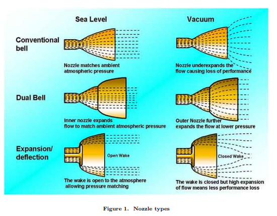
Altitude-compensating nozzles. Altitude compensating nozzles address this loss of efficiency by changing the shape or volume of the rocket nozzle as the rocket climbs through the atmosphere. There are a wide variety of designs that achieve this goal, with the aerospike being perhaps the most studied among them.
https://en.wikipedia.org/wiki/Altitude_ … ing_nozzle
https://exoscientist.blogspot.com/2014/ … s-for.html
rocket engine altitude compensating nozzle images
Simple equational components
simple rocket 
Could a mixed fuel types of injection be the answer?
Offline
Like button can go here
#3 2019-07-08 19:56:00
- kbd512
- Administrator
- Registered: 2015-01-02
- Posts: 8,516
Re: A SSTO research project.
This is probably one of the few broadly useful things New Mars Forums members could actually do to contribute to rocketry, so why not?
You might want to see if GW can double-check the math and if Josh can use his MATLAB access to run numerical analyses for us. You'll also need someone with GW's experience to tell us what kinds of materials and geometries could realistically work for the combustion chamber and nozzle configurations you had in mind as well. Sometimes CFD codes don't agree with the real world and you'll need real world agreement here.
I write code in Java, JavaScript, and also use lots of pl/sql at work. I'm most familiar with Oracle databases and object databases. By trade, I work on statistical analysis software for forecasting. Between SQL and object databases, I'd recommend using the object databases for this application, assuming speed is at all important to you. I haven't written anything in C++ since college, so you're SOL there.
If you need someone to help with the programming work or data analysis, I'm game.
Offline
Like button can go here
#4 2019-07-08 20:44:15
- SpaceNut
- Administrator
- From: New Hampshire
- Registered: 2004-07-22
- Posts: 30,595
Re: A SSTO research project.
Here is the other topic with altitude compensation in BFS becomes SSTO with altitude compensation.
I think this one also applies in Towards highly reusable rocket engines
Advanced Aerospike Rocket Engine Design
Anyone know anything about engine Nozzles? - Ablative Nozzles
Offline
Like button can go here
#5 2019-07-12 15:31:06
- GW Johnson
- Member
- From: McGregor, Texas USA
- Registered: 2011-12-04
- Posts: 6,168
- Website
Re: A SSTO research project.
What I think you will find is that any sort of free-expansion design is only marginally better (a single digit percentage) in terms of Isp than a fixed nozzle that just barely does not separate at sea level. A single digit percentage in midrange better, and no better or maybe worse at sea level, and certainly worse in real vacuum. The net benefit is very small, far less than estimates made by incorrectly assuming vacuum Isp levels for a nozzle that is typically too expanded not to separate at sea level.
The variable geometry designs are going to be heavier than either the conventional nozzle or the free-expansion designs. Depending upon cooling requirements, the free expansion designs may (or may not) be heavier than a conventional bell.
The "right" design for a conventional bell is being designed at about 20,000 feet altitude backpressure (for chamber pressures in the 1000 psia class). It will not separate at sea level, so it flows full, and at a higher exit Mach number than a true sea level design. You get the best Isp vs altitude trend with it, at the cost of slightly-reduced absolute thrust at sea level, peak thrust occurs at the design altitude of 20,000 feet.
It also gives fairly good vacuum performance, and without any moving parts. The exit Mach term is more important to performance than the exit - ambient backpressure term. F = etanoz mdot Vex + (Pex - Pamb)Aex = [Pex(1 + gamma etanoz Mex^2) - Pamb]Aex. The square on exit Mach is why it is more important to your outcome than Pex - Pamb. Most propellant combinations have gamma very nearly 1.20. Solids, too.
Low etanoz in vacuum is why performance of the free expansion designs is lousy out in vacuum. The exit streamlines diverge way too strongly. Fixed bell geometries do not suffer from that. You can estimate etanoz as 0.5(1 + cosine (halfangle)), where halfangle is the effective average streamline divergence angle (off of axial) of the stream's outer boundary.
GW
Last edited by GW Johnson (2019-07-12 15:41:48)
GW Johnson
McGregor, Texas
"There is nothing as expensive as a dead crew, especially one dead from a bad management decision"
Offline
Like button can go here
#6 2019-07-12 18:59:41
- SpaceNut
- Administrator
- From: New Hampshire
- Registered: 2004-07-22
- Posts: 30,595
Re: A SSTO research project.
Here is some of the alphabet soup that GW is talking about... https://en.wikipedia.org/wiki/Rocket_engine_nozzle
This is in the realm of what space x did with its Merlin engine for how it compensated the engine for the stages
https://www.reddit.com/r/spacex/comment … re_merlin/
https://en.wikipedia.org/wiki/Merlin_(r … ne_family)
Spacex is using a dual bell for its Raptor engines
Offline
Like button can go here
#7 2019-07-13 15:41:33
- GW Johnson
- Member
- From: McGregor, Texas USA
- Registered: 2011-12-04
- Posts: 6,168
- Website
Re: A SSTO research project.
Of all the "self-compensating nozzle" ideas I have run across, the dual bell idea in Spacenut's post 6 is the best. THAT is the one you should pursue, Bob Clark!
The sharp corner at the change in bell profiles is a bit of risk as a stress concentrator, and a heat transfer concentrator, and as the locus of locally-enhanced erosion, but it might well be worth it. Especially since Spacex seems to be successful with it so far in their Raptor engines.
It takes a sharp change in surface profile to enforce the reliable flow separation location. That is inherent. If you don't do that, separation is not predictable, and neither is performance.
The expansion-deflection nozzle always looks good in textbooks, but NOT in the real world, where you have to hang onto highly-loaded structure immersed in hot gas at full chamber conditions. Not just temperature, but pressure, too.
Density affects heat transfer coefficients as much as velocity. The heat transfer problem has always been insoluble for real-world applications. The only exception I know of was a limited-life ablative-protected variable geometry nozzle developed but not used in ASALM-PTV.
It was a rotating paddle located in the throat plane. Streamline was large throat, broadside obstructed was small throat. The wake had to close by the exit plane in either configuration, or your nozzle efficiency was utter crap, in real tests. Including hot fire tests, to a max 900 seconds of burn time.
The real question for Bob's effort is whether the weights and risk-reduction features of the dual bell approach are worth the net overall Isp improvement over the slightly-simpler 20 kft single bell that I have long favored.
I would be interested to know the outcome of that question.
GW
Last edited by GW Johnson (2019-07-13 15:45:40)
GW Johnson
McGregor, Texas
"There is nothing as expensive as a dead crew, especially one dead from a bad management decision"
Offline
Like button can go here
#8 2019-07-13 17:07:06
- kbd512
- Administrator
- Registered: 2015-01-02
- Posts: 8,516
Re: A SSTO research project.
GW,
It's worth it if a booster like the one that powers Falcon 9 / Falcon Heavy even has a few more percentage points of propellant left for the landing, so as to restore diminished payload capacity as a function of propellant reserve required for booster recovery. We've spent untold billions attempting to achieve a few more percentages points of efficiency in jet engines. A 5% increase in performance is huge.
Regarding launching from higher altitudes, why not launch from 40,000 ft using something like StratoLaunch?
You don't need a pad, the booster is smaller, you start higher in the atmosphere to capitalize on less atmospheric pressure and drag, any airport can be converted to a space port, and you can launch to any orbit. This makes good sense to me if we're trying to achieve economies of scale. Most of the payloads will be smaller satellites. Since we send single astronauts to space most of the time, it makes sense for that, too. Why not recover the booster downrange in mid-air using the launch vehicle to negate the need for landing hardware / propellant?
Why not combine all of those techniques to produce a significant performance improvement that makes space launch a truly routine phenomenon?
Offline
Like button can go here
#9 2019-07-14 15:10:44
Re: A SSTO research project.
Of all the "self-compensating nozzle" ideas I have run across, the dual bell idea in Spacenut's post 6 is the best. THAT is the one you should pursue, Bob Clark!
The sharp corner at the change in bell profiles is a bit of risk as a stress concentrator, and a heat transfer concentrator, and as the locus of locally-enhanced erosion, but it might well be worth it. Especially since Spacex seems to be successful with it so far in their Raptor engines.
...
GW
Unfortunately, it didn’t match the maximum Isp of vacuum optimized upper stage engines. I discuss a report studying using the dual-bell on the Ariane 5’s Vulcain engine here:
https://www.researchgate.net/project/Si … 968db26381
It raised the vacuum Isp from 432s to only 438s, far from the max 465.5s already achieved with the RL10. It resulted in only a 5% increase of the payload to GTO, ca. 500kg.
Bob Clark
Last edited by RGClark (2019-07-14 15:11:34)
Old Space rule of acquisition (with a nod to Star Trek - the Next Generation):
“Anything worth doing is worth doing for a billion dollars.”
Offline
Like button can go here
#10 2019-07-14 15:52:46
- GW Johnson
- Member
- From: McGregor, Texas USA
- Registered: 2011-12-04
- Posts: 6,168
- Website
Re: A SSTO research project.
Bob:
Unfortunately, despite the erroneous common belief otherwise, there is simply no such thing as a "vacuum-optimized bell nozzle". There is only however much bell expansion ratio you can afford to add. The more expansion, the higher the vacuum Isp.
But beyond a very limited (!!!) enhanced expansion ratio, it won't work at sea level, because it cannot avoid separated flow. The dual bell idea gives it a definite place to separate for repeatable separated performance. Nothing more.
No self-compensating design of any kind will ever approach the vacuum Isp of a high expansion ratio bell nozzle. That's limited by expansion physics. Period.
That would be expansion ratios in the 40-100 class, at nominal chamber pressures of 1000+ psia. These are limited by how much exit area will actually fit behind your stage, simple as that. Or added weight, if you happen to bump into that constraint. Or the max interstage length you have to contain your elongated bell, if you happen to bump into that constraint.
GW
GW Johnson
McGregor, Texas
"There is nothing as expensive as a dead crew, especially one dead from a bad management decision"
Offline
Like button can go here
#11 2019-07-14 17:01:34
- SpaceNut
- Administrator
- From: New Hampshire
- Registered: 2004-07-22
- Posts: 30,595
Re: A SSTO research project.
http://marsforthemany.com/news/technolo … et-engine/
Note: other hydrocarbon-based fuels can also be manufactured on Mars, but they all have lower ISPs than methane, so a methane rocket engine is typically the engine most discussed. Here's a quick chart if you are interested.

So what would the ideal ISP for mass to orbit in a single stage delivered which is reuseable...
How does that ISP change with altitude?
RL10 engine can be made to work with many fuels but they are custome optomized for them....
Offline
Like button can go here
#12 2019-07-14 17:19:59
- kbd512
- Administrator
- Registered: 2015-01-02
- Posts: 8,516
Re: A SSTO research project.
GW,
Would it be possible to mitigate the effects of flow separation so we can still use larger fixed nozzles?
Effect of air jet vortex generators on a shock wave boundary layer interaction
Control of Flow Separation in a Rocket Nozzle Using Microjets
Offline
Like button can go here
#13 2019-07-16 00:28:56
Re: A SSTO research project.
http://marsforthemany.com/news/technolo … et-engine/
Note: other hydrocarbon-based fuels can also be manufactured on Mars, but they all have lower ISPs than methane, so a methane rocket engine is typically the engine most discussed. Here's a quick chart if you are interested.
http://marsforthemany.com/wp-content/up … risons.png
So what would the ideal ISP for mass to orbit in a single stage delivered which is reuseable...
How does that ISP change with altitude?
RL10 engine can be made to work with many fuels but they are custome optomized for them....
Thanks for that link. The vacuum Isp is highly dependent on nozzle size, or nozzle area ratio. For instance the hydrolox RL10-B2 engine with its long nozzle extension can get 465.5s Isp. And the methanolox vacuum Raptor is expected to have a 382s vacuum Isp.
Back in the late 90’s there was a lot of interest in SSTO’s with the research on the X-33 and the DC-X. Here’s a report that explored the options for fuels for an SSTO:
Alternate Propellants for SSTO Launchers.
Dr. Bruce Dunn
Adapted from a Presentation at:
Space Access 96
Phoenix Arizona
April 25 - 27, 1996
https://web.archive.org/web/20140215015 … llants.htm
It turned out the dense propellants offered better payload since their lower Isp was more than made up for by their higher mass ratios.
Bob Clark
Old Space rule of acquisition (with a nod to Star Trek - the Next Generation):
“Anything worth doing is worth doing for a billion dollars.”
Offline
Like button can go here
#14 2019-07-16 00:35:25
Re: A SSTO research project.
GW,
Would it be possible to mitigate the effects of flow separation so we can still use larger fixed nozzles?
Effect of air jet vortex generators on a shock wave boundary layer interaction
Control of Flow Separation in a Rocket Nozzle Using Microjets
Yes. These should work. In fact there are several ways of doing it. The only hindrance is that there isn’t a simple way of calculating the delta-v and payload with alt.comp. nozzles compared to fixed nozzles, where you can just use the well-known rocket equation.
So nobody knows how the payload is improved using it.
Bob Clark
Last edited by RGClark (2019-07-16 00:36:29)
Old Space rule of acquisition (with a nod to Star Trek - the Next Generation):
“Anything worth doing is worth doing for a billion dollars.”
Offline
Like button can go here
#15 2019-07-16 08:24:04
- GW Johnson
- Member
- From: McGregor, Texas USA
- Registered: 2011-12-04
- Posts: 6,168
- Website
Re: A SSTO research project.
Kbd512:
I think the microjet idea offers more potential for rocket nozzle separation than the vortex generator idea. No physical structures are going to be survivable at rocket nozzle conditions, not with any materials known to man. The microjet idea is still years away from application, because if you botch the injection, you make shock-separation worse instead of better. The jet can easily act like a blockage to the flow, creating a shock you did not intend.
Bob Clark:
What I think you will find is that Isp trend vs altitude for a self-compensating nozzle of almost any design will look an awful lot like the trends I got for free-expansion nozzles. Comparing those to a fixed bell nozzle designed at about 20 kft (so that it is overexpanded but not separated at sea level), the free expansion designs looked a few % worse at sea level, a few % better near their design altitude, and a whole lot worse (multiple 10's of %) in actual vacuum. Streamline divergence approaching 90 degrees just kills vacuum nozzle efficiency with free expansion designs.
That's why I said pursue the dual bell. It'll be no better than a conventional nozzle at sea level, and no better than a moderate-altitude conventional nozzle at high altitudes still in the atmosphere, but it will achieve the vacuum Isp of a possibly-more-aggressive vacuum design conventional bell in true vacuum. That is where are the free expansion designs fall way short. But the differences in Isp trend with altitude will not be largely different from a 20 kft bell. It may be better, but not dramatically.
What you will find for vehicle design is that for chemical propulsion, payload fractions to LEO will be quite small (~1% or less) with single stage designs that do not reflect the enhanced robustness needed for reusability. Two stage, everything looks a whole lot more favorable, even with reusability built in. Aluminum-lithium alloy tankage in the first stage is feasible because entry speeds are far lower than for entry from orbit. But it's not a long-life material at those near-yield stress levels at elevated temperatures. Maybe 10 cycles or thereabouts, max.
If you go SSTO, accepting the low payload fractions (higher cost), you will need to solve the orbital entry speed problem, which incurs higher weights, higher costs, and precludes bare aluminum tankage. So far, no one has a demonstrated solution. The Spacex Starship is still an undemonstrated proposal, although it might work if they use some PICA-X on its windward surfaces.
GW
Last edited by GW Johnson (2019-07-16 08:25:00)
GW Johnson
McGregor, Texas
"There is nothing as expensive as a dead crew, especially one dead from a bad management decision"
Offline
Like button can go here
#16 2019-07-16 11:23:35
Re: A SSTO research project.
Hey RGClark,
I'm very interested in this project and would be glad to offer what help I can. As kbd512 noted I have access to and experience with matlab and have done some similar-ish modelling in the past. I will read your posts on researchgate and do some thinking about this tonight and write up a reply with my thoughts as soon as I can.
-Josh
Offline
Like button can go here
#17 2019-07-16 11:37:02
Re: A SSTO research project.
Here's the equation showing exhaust velocity dependent on nozzle exit pressure:

from,
https://en.m.wikipedia.org/wiki/Rocket_ … ne_nozzles
So we can calculate the Ve given the other parameters such as combustion temperature, molecular weight of the combustion products, etc. We can get those as calculated by the program Rocket Propulsion Analysis: http://propulsion-analysis.com/index.htm
It's a derivative with user-friendly GUI of the program ProPEP. The program also calculates the vacuum and sea level Isp of the engine. I've found the vacuum Isp it calculates to be reasonably accurate for known engines. However, the sea level estimate it I found is not. I don't know why that is if anyone wants to experiment with the program.
Still we can use it to calculate the parameters that go into the Ve equation above, then use that equation to calculate the Ve. Because of inefficiencies in nozzles, you won't get the exact value. But rocket engines are pretty efficient, commonly at the 96% range, so the Ve calculated should be pretty accurate.
Here's a graphic that shows what the Isp of the Vulcain 1 engine would be if it had ideal expansion at all levels:

Taken from:
Advanced Rocket Nozzles
August 1998 Journal of Propulsion and Power 14(1998):620-633
Source DLR
Gerald Hagemann Hans Immich T. van Nguyen G.E. Dumnov
https://www.researchgate.net/publicatio … et_Nozzles
You see the ideal expansion case is significantly better than the fixed nozzle case both at sea level and vacuum. We can use the graph to estimate the Isp for the alt. comp. case, at least for the Vulcain 1 engine. Also, by comparing the graph to our calculations we can determine how accurate our Ve calculations are.
But we still need to calculate the delta-v for other engines, such as the hydrolox RS-68 on the Delta IV, the kerolox Merlin on the F9, and the methanolox Raptor on the BFR.
Here's a graphic showing ideal expansion in general:

The parameter being displayed on the y-axis is nozzle thrust coefficient, not exhaust velocity. But they are proportional so the exhaust velocity graph would have a similar shape. If by comparing our Ve calculations for the Vulcain 1 to the graphic for the Vulcain 1 case, we can conclude out calculations are accurate then that will bolster our confidence in using the Ve equation for the other engines.
Bob Clark
Last edited by RGClark (2019-07-16 11:42:21)
Old Space rule of acquisition (with a nod to Star Trek - the Next Generation):
“Anything worth doing is worth doing for a billion dollars.”
Offline
Like button can go here
#18 2019-07-17 12:00:39
- GW Johnson
- Member
- From: McGregor, Texas USA
- Registered: 2011-12-04
- Posts: 6,168
- Website
Re: A SSTO research project.
The nozzle exit pressure in the equation shown in post 17 is the expanded pressure inside the nozzle, not the ambient pressure surrounding it. This pressure is fixed for a given chamber pressure, because their ratio is fixed by the bell's area ratio. That's just fluid mechanics of nozzles.
I put all the conventional bell nozzle ballistics up on exrocketman, in the posting titled "Back of the Envelope Rocket Propulsion Analysis" dated August 23, 2018. There's some more in another posting titled "How Propulsion Nozzles Work" dated November 12, 2018, that also includes a couple of free expansion designs for direct comparison.
The relevant equations are given in those articles, along with examples as a guide to how to use these equations properly (do it wrong, and you get bad answers). I cast the analysis equations for nozzles in terms of expanded exit Mach instead of absolute velocity, because that's more convenient for standard compressible fluid flow analysis. I cast the thrust coefficient equation in those same variables and for the same reason: convenience.
You usually decide upon an expanded pressure ratio Pe/Pc where Pe is the expanded pressure and Pc the chamber pressure just upstream of the nozzle contraction into its throat. If you have a specific heat ratio for your hot gas (usually pretty close to 1.20), use that with the compressible isentropic relation to determine exit Mach Me.
Then use that and specific heat ratio in the compressible isentropic streamtube equation to determine the geometric area ratio Ae/At, where Ae is the exit plane area, and At is the throat plane area.
From there, if you have a nozzle kinetic energy efficiency etanoz, and an ambient backpressure Pa, thrust is then F = [Pe (1 + gamma etanoz Me^2) - Pa]Ae, or in thrust coefficient form CF = [Pe/Pc (1 + gamma etanoz Me^2) - Pa/Pc] Ae/At, for use in F = CF Pc At.
Note that Pe Ae is the exit plane pressure twerm, -PaAe is the ambient backpressure term, and Pe Ae gamma etanoz Me^2 is the flowrate x exhaust velocity term, in the thrust equation most are more familiar with: F = flow rate x exhaust velocity + (Pe - Pa)Ae.
And etanoz is primarily the effect of streamtube divergence as controlled by the shape of your expansion bell. etanoz = 0.5 (1 + cosine a) where a = average half angle of the bell shape.
I have some spreadsheets already set up to do this kind of analysis, and some of these Bob already has. If Bob or Josh needs more, let me know.
GW
Last edited by GW Johnson (2019-07-17 12:18:42)
GW Johnson
McGregor, Texas
"There is nothing as expensive as a dead crew, especially one dead from a bad management decision"
Offline
Like button can go here
#19 2019-07-19 09:59:27
Re: A SSTO research project.
Here is some of the alphabet soup that GW is talking about... https://en.wikipedia.org/wiki/Rocket_engine_nozzle
This is in the realm of what space x did with its Merlin engine for how it compensated the engine for the stages
https://www.reddit.com/r/spacex/comment … re_merlin/https://en.wikipedia.org/wiki/Merlin_(r … ne_family)
Spacex is using a dual bell for its Raptor engines
There was speculation that SpaceX was using a dual-bell nozzle on the Raptor based on early, mock-up images of the Starhopper. However, later images of the Raptor showed it used a standard bell nozzle.
There is, so far, no evidence SpaceX intends to use altitude compensation on any of its rockets.
Bob Clark
Old Space rule of acquisition (with a nod to Star Trek - the Next Generation):
“Anything worth doing is worth doing for a billion dollars.”
Offline
Like button can go here
#20 2019-07-19 10:22:32
Re: A SSTO research project.
Hey RGClark,
I'm very interested in this project and would be glad to offer what help I can. As kbd512 noted I have access to and experience with matlab and have done some similar-ish modelling in the past. I will read your posts on researchgate and do some thinking about this tonight and write up a reply with my thoughts as soon as I can.
I did some preliminary calculations of the Ve from the equation I cited in post #17 and found it was in reasonable agreement to the graph of the Vulcain 1 under ideal expansion in that post. So we can use the equation with some efficiency factor of, say, .96 to .98, to calculate the Isp dependent on altitude for different engines.
As I mentioned I got the engine parameters such as combustion temperature, combustion products molecular weight, specific heat, etc., from the Rocket Propulsion Analysis program, http://propulsion-analysis.com/index.htm , to plug into the formula.
You can do a graph to see if you do get a similar shaped graph when you do the calculations for other engines under ideal expansion.
We also need to do the flight trajectory simulation for alt.comp. engines. For this first level calculation we can do a “gravity turn” trajectory:
https://en.m.wikipedia.org/wiki/Gravity_turn
I’m looking for simple references to use for this calculation.
Bob Clark
Last edited by RGClark (2019-07-19 10:26:12)
Old Space rule of acquisition (with a nod to Star Trek - the Next Generation):
“Anything worth doing is worth doing for a billion dollars.”
Offline
Like button can go here
#21 2019-07-19 12:05:22
- GW Johnson
- Member
- From: McGregor, Texas USA
- Registered: 2011-12-04
- Posts: 6,168
- Website
Re: A SSTO research project.
You can do a reasonably good estimate of a non-lifting gravity turn trajectory as a 2-D point mass model, with thrust, weight, and drag accounted for. No need for more sophisticated 3-dof or 6-dof models. You will need to model thrust vs altitude and maybe power setting, drag vs Mach, and some model of weight vs time allowing for changes in flow rate with power setting. It works better as a spherical coordinates model than as a 2-D Cartesian model.
GW
GW Johnson
McGregor, Texas
"There is nothing as expensive as a dead crew, especially one dead from a bad management decision"
Offline
Like button can go here
#22 2019-07-19 13:54:20
Re: A SSTO research project.
I've given the project some thought, and what I've come up with is that it would take some work to complete to my satisfaction. Here's how I think about it:
After some analysis of various engine designs, we will create a curve which we believe predicts, with reasonable accuracy, the performance of a rocket engine as a function of external pressure (not altitude; pressure, for reasons that will become clear). We will do this both for a standard bell nozzle (perhaps also for an overexpanded and underexpanded nozzle) and for one or several kinds of altitude compensating nozzles.
In an idealized case, we would create a trajectory-averaged value for the Isp of the rocket engine, then, knowing the delta-V required to get to orbit we would plug in to the rocket equation to get the dry mass fraction; subtract out engine and structural mass and what's left is the payload. This is not a viable approach for reasons I will describe, but before I do I want to distinguish between how I would approach the problem in a forum post vs a research paper.
For all our technical excellence, the Newmars forums are neither peer reviewed nor generally advisory. It would be acceptable, and indeed quite valuable on the forums, to come up with a rough weighting scheme (linearly increasing, perhaps), tweak the coefficients until they work with existing rockets, throw the new numbers into the blender, and see what comes out. A method like this is approximate, but the numbers that come out really would add new information to a discussion.
For scientific purposes, this method is indefensible analytically and uses inadequate data to provide a useful empirical result. A valid result would be one that doesn't just give something like a correct answer but does so in such a way as to give confidence in the correctness of that answer. In this case, that means building a kinematic model of a surface to orbit launch.
So, okay, a kinematic model isn't too hard to build. Sum the forces in x and z (at a first approximation there's no out of plane forces). ΣF=ma (bolding indicates a vector quantity). There's only three forces on the rocket: Gravity, thrust, and drag.
Gravity is a simple function of altitude, always pointed towards the center of the Earth, and can be calculated easily and with acceptable accuracy using Newton's law of gravitation.
Rocket thrust is proportional to Isp. Isp varies according to external pressure. However, as GW and Bob Clark's reference have noted this is not the external atmospheric pressure. The ship necessarily shields the engines from the flow of supersonic air, creating a bubble of stationary air beneath it. Because of the Bernoulli effect (and its supersonic equivalents, if they are to be considered different) this air is at a lower pressure than you might calculate using the barometric formula.
Finally, air drag, a tricky phenomenon also. GW could maybe recommend or provide a calculation for air drag as a function of altitude and speed? This isn't something I know well.
I need to familiarize myself better with the gravity turn maneuver (as well as convince myself that it's optimum or near-optimum compared to alternatives), but determining the optimum time, duration, and angle of the pitchover to achieve the correct orbit with the maximum payload seems like a nontrivial (read: conceptually simple but time consuming on my underpowered PC) task unless there's guidelines for what the correct parameters are. It's worth noting that questions of how you deal with Max-Q and engine throttling parameters will have a substantial effect as well.
Anyway it's definitely something I'd be able to simulate (for the record I'd stick with Cartesian space, not that it matters) given the correct inputs and some more thinking on the launch trajectory.
-Josh
Offline
Like button can go here
#23 2019-07-19 16:40:53
- GW Johnson
- Member
- From: McGregor, Texas USA
- Registered: 2011-12-04
- Posts: 6,168
- Website
Re: A SSTO research project.
Josh:
For a nonlifting trajectory (gravity turn), angle of attack is pretty near zero, so there is no induced drag-due-to-lift. There is only parasite drag, which in coefficient form is a function of Mach number.
The vehicle drag at any given flight condition is then D = CD Aref q, where Aref is the reference area upon which CD is based, and q is the dynamic pressure. CD vs Mach is usually constant from Mach 0 to about 0.8-ish, rising suddenly to a peak at about Mach 1.1-ish, and slowly decreasing at supersonic Mach numbers.
It usually sort of flattens out at hypersonic Mach numbers, which are Mach 3+ for a blunt object, and Mach 5+ for a pointy object. The transonic peak is usually around twice the subsonic value, and the hypersonic value is usually around 2/3 the subsonic value. That would pertain to a sort-of "pointy" artillery shell shape, rather similar to most launch rockets. Sighard F. Hoerner's old self-published drag bible titled "Fluid Dynamic Drag" has a lot of real wind tunnel test data in it. My copy is the 1965 edition.
Dynamic pressure is half the ambient density times the flight speed squared. But if you work instead in Mach number (convenient for the aerodynamics), q = 0.5 gamma P Mach^2, where gamma is the air specific heat ratio (near 1.4), and P is the ambient atmospheric pressure at whatever your flight condition is. At very high speeds, gamma is a bit less than 1.4. You figure it at total temperature, not static temperature.
The wake suction behind a stage is a second-order effect at best. I wouldn't sweat that too much. Calculating it from first principles is "iffy" indeed, and you are far better off just using real test pressure coefficient data for aft-facing surfaces of an appropriate shape. The further your engine bell projects aft from the aft-facing surface, the smaller that wake suction effect is. That's why most of us who did this stuff for a living just ignore it.
For any fixed bell type of rocket nozzle, if you can determine its vacuum thrust Fvac and you know its exit area Aexit, you can figure thrust F at any ambient atmospheric pressure Pamb as F = Fvac - Pamb Aexit. This presumes no backpressure-induced separation ever occurs. If Pamb > Psep, separation will occur. How much thrust you can get once separation occurs is rather unpredictable. At best.
I have a separation criterion which works fairly well. It is Psep/Pc = (1.5 Pexit/Pc)^0.8333, where Pc is the chamber pressure feeding the nozzle, and Pexit is the expanded pressure at the exit plane, locked in by Pc and the area ratio Aexit/Athroat. It is entirely empirical.
GW
Last edited by GW Johnson (2019-07-19 16:47:24)
GW Johnson
McGregor, Texas
"There is nothing as expensive as a dead crew, especially one dead from a bad management decision"
Offline
Like button can go here
#24 2019-07-19 16:54:53
- SpaceNut
- Administrator
- From: New Hampshire
- Registered: 2004-07-22
- Posts: 30,595
Re: A SSTO research project.
Rockets fly on an arc not a straight line so as to be able to intercept the orbit altitude target which changes the fuel mass depending on the time to that location. The payload mass will effect that time as well.
Offline
Like button can go here
#25 2019-07-21 09:34:05
- GW Johnson
- Member
- From: McGregor, Texas USA
- Registered: 2011-12-04
- Posts: 6,168
- Website
Re: A SSTO research project.
That arc is the gravity turn, Spacenut. You have to figure it numerically. Smaller step size is better accuracy, but more voluminous calculations.
For a nonlifting point mass model, thrust and drag are tangent to the trajectory, while weight is at an ever-increasing angle to that tangent, as the trajectory bends over. It is the component of weight normal to the trajectory tangent that bends the trajectory, from each discrete time step to the next.
In the old days with limited computer power, they would use one or another version of Runge-Kutta integration to do the numerical simulation accurately enough. Today you can use a simple first-order forward-stepping model with a fine time step: the computer is now good enough not to care, or be perceptually-slowed, by that.
I have even used an adaptive time step set by the max tolerable change in velocity from one step to the next, say at most 10%. Adaptive time step runs into trouble at launch because velocity is zero there, so you need a default minimum time step and some error-trapping on the tangential-acceleration/change-in-velocity calculation to avoid dividing by zero when you figure the next time step.
In a 2-D Cartesian point mass model with trajectory angle theta measured from horizontal, ax = [(F - D) cosine theta] / mass, and ay = [(F - D) sine theta - W]/mass, where W = mass * g and mass varies with time and thrust level. ax is the x-direction acceleration, and ay is the y-direction acceleration. Their 90-degree vector sum is the tangential acceleration. Divide that by the allowable velocity change to calculate the next time step.
You cannot start at theta = 90 degrees at time zero, because the trajectory will never bend in the model. You will have to start at 89-plus-some-decimal degrees. You run the model multiple times varying this initial launch angle until the end of the trajectory is at the altitude and theta that you want. (In the real world it launches at 90 degrees, but pitches to the "right" theta as soon as it clears the tower.)
Josh - does that description of the dynamics model help out with your calculation? I don't know any of the modern things like MATLAB. The last times I did this sort of thing I was using either advanced BASIC or FORTRAN IV. Those were decades ago.
It was iterative just like that running NEMAR at LTV Aerospace for "Scout" launches back in 1974. NEMAR had an adaptive time step, that’s where I learned that cute little trick. Except that NEMAR was 6-dof, with nonzero angles of pitch and yaw capability. "Scout" was a four-stage vehicle. We had serial calculation phases, one for each stage. Our target was the altitude and theta for the orbit insertion conditions we wanted. The insertion velocity was what it was from the calculation, because all the stages were solids. They burn to completion, period. (Liquids you can cut off before the pumps cavitate.)
GW
GW Johnson
McGregor, Texas
"There is nothing as expensive as a dead crew, especially one dead from a bad management decision"
Offline
Like button can go here