New Mars Forums
You are not logged in.
- Topics: Active | Unanswered
Announcement
#1 2024-05-23 02:53:18
- kbd512
- Administrator
- Registered: 2015-01-02
- Posts: 8,518
SSTO Airframe and TPS Materials
I'm starting this topic to discuss what I think will become the airframe and thermal protection system materials of choice for a practical SSTO.
Airframe Structural Materials
TorayCA Carbon Fiber Selector Guide
TorayCA T1200 fiber - Introduced 2023
Tensile Strength: 1,160ksi; Density: 1.82g/cm^3
TorayCA T1100 fiber - Introduced 2014
Tensile Strength: 1,017ksi; Density: 1.79g/cm^3
TorayCA T1000 fiber - Introduced 1986
Tensile Strength 856ksi; Density: 1.8g/cm^3
PROOF Research Advanced Composites Division 900HT Polyimide Thermoset Resin
Neat Resin Density: 1.33g/cm^3
Maximum 1 Minute Heating Transient: 1,300°F / 704°C
Maximum Dry Continuous Service Temperature: 650°F / 343°C
Maximum Wet Continuous Service Temperature: 550°F / 288°C
TorayCA TC890 / PROOF 900HT Pre-Preg System
Shelf Life (ambient temp): 30 days
Shelf Life (frozen): 12 months
Resin Curing: 2hrs at 700°F / 371°C
This is how we can be reasonably certain that 900HT resin will perform at 350°F, because it's curing temperature is twice as high.
TorayCA's US-based T1100 fiber plant is located in Decatur, AL.
Thermal Protection System Materials
Reinforced Carbon-Carbon for Nose Cap and Wing Leading Edges
UltraMet Carbon-reinforced Aerogel-filled Reusable Foam Insulation for High Heat
Maximum Service Temperature: 4,500°F / 2,482°C
Density: 4.4lbs/ft^3
Backside Temperature after 243s test at 3,500°F / 1,927°C: 350°F / 177°C
UltraMet's facility is located in San Fernando Valley, Los Angeles, CA.
A good portion of the vehicle will be covered by the flexible fabric blanket material
The Space Shuttle's External Tank, plus 10% to 15% extra volume, IIRC, encloses enough propellant volume to send my proposed 500 passengers to orbit (39,750kg for 500 fully suited passengers falling into the 95 percentile with 2L of water and 3 meals), according to the Silverbird Astronautic's Payload Calculator tool. If it was a cylinder of the same length, then it's total surface area is 14,500ft^2. The total surface area of all TPS materials used by the Space Shuttle was 26,100ft^2. Let's assert that our surface area will be 52,200ft^2 and that we need 1 inch thick UltraMet tiles over the entire vehicle's surface area. This is far greater than what I expect my notional SSTO's total surface area to be, but I'm doing this to illustrate a point.
52,200ft^2 = 7,516,800in^2
7,516,800in^2 / 1,728in^3 per 1ft^3 = 4,350ft^3
Hopefully it's understood by readers that multiplying by 1, for the 1 inch thick tiles, in order to arrive at cubic inches, is superfluous.
4,350ft^3 * 4.4lbs/ft^3 = 19,140lbs / 8,682kg
Notional LOX/LCH4 SSTO Gross Liftoff / Wet Mass: 2,125,000kg
Space Shuttle Super Light Weight External Tank: 26,536kg (treat as airframe mass, less engines, landing gear, life support)
12X Raptor 3 engines: 19,200kg (provides a 1.5:1 thrust-to-weight ratio at liftoff, based upon current / tested Raptor performance)
UltraMet 1in thick tiles to cover a vehicle 2X as large as the orbiter: 8,632kg (withstands higher temps than Space Shuttle leading edges while remaining within composite temperature limits on the backside of the TPS)
500 passengers in pressure suits with 2L water and 3 meals: 39,750kg (not carrying anything else with them except for a small O2 bottle for emergencies)
Landing Gear: ???kg
Thrust Structure: ???kg
Life Support Equipment: ???kg (CO2 scrubbers, fans, waste heat removal)
Fuel Cell Equipment: 16kg for 125kWe at 8kWe/kg
Control Surface Actuators: ???kg (Space Shuttle EHDUs peaked at 90kW in total, I think)
Avionics and Sensors: 50kg
Cockpit Flight Controls: 50kg
Reaction Control System: ???kg (will use residual gaseous O2 and CH4 from the main tanks)
Airframe + TPS + Engines = 54,368kg
Expected Total Dry Vehicle Weight: 60,000kg
Passengers = 39,750kg
Total Payload Weight: 99,750kg
Silverbird Astronautics Payload Estimation: 80,950kg (95% Confidence Interval is 56,290kg - 110500 kg) from Cape Canaveral to a 185km by 185km orbit, 45 degree inclination
2,000,000kg of propellant; 31,654kN of thrust from the 12 Raptors; 353.5s Avg Isp used
Launch Vehicle Performance Estimation Methodology
I budgeted 5,516kg for everything with a question mark next to it. I may need to add more mass for the RCS, but it won't be a totally separate system. We have somewhere between 1% to 3% of our liftoff propellant mass, in the form of residual gaseous propellant, so we're going to work with that for RCS and the reentry burn, and possibly to power the fuel cells as well. Waste not, want not. This has to be an integrated vehicle design where all the systems work together, rather than creating a myriad of separate subsystems that add weight and cost to an already costly vehicle. The engines will use non-regeneratively cooled ceramic coated RCC nozzles for weight reduction and engine simplification. I expect to save about 100kg per engine.
Landing Gear and Thrust Structure will primarily use high strength composites, rather than steel. Life Support will use deployable CNT ribbon radiators to get rid of the waste heat from 500 passengers. Current fuel cell tech for cars is 8kWe/kg. 48hrs is the max mission duration. You either rendezvous with your colonization ship within 24 hours, or you abort and land.
Offline
Like button can go here
#2 2024-05-23 03:44:17
- kbd512
- Administrator
- Registered: 2015-01-02
- Posts: 8,518
Re: SSTO Airframe and TPS Materials
The TPS mass I quoted might be unrealistically high, because it's based upon an unrealistically high surface area that's 3.6X greater than that of the Space Shuttle External Tank, since most of this vehicle's volume and surface area is attributable to its propellant tanks. The wings will be larger than Space Shuttle's wings, but not by that much. Space Shuttle's max landing weight was 94,000kg. If this vehicle returns with all of the passengers, then it would only weigh 6% more, so if we have a 10% greater wing area, plus the entire external tank surface area, that doesn't amount to 3.6X more than the Space Shuttle.
T1200 fiber in a tape-wound composite (572ksi) has approximately 6.98X greater yield strength than Al-2195-T8 (82ksi) and CFRP is roughly twice as resistant to deformation under load, ignoring geometry and thickness, so I think I have sufficient strength and stiffness incorporated into that 26,536kg worth of structural mass for the airframe (propellant tanks, cabin, wings). Maybe I don't, but the composite density is 1.624g/cm^3. That means I have 16.34m^3 of material to work with, as compared to 9.83m^3 of Al-2195, ignoring the fact that 2,188kg of the Space Shuttle External Tank's weight was spray-on foam insulation rather than structural metal. In essence, I have 66% greater volume of material for the same weight. I should have an incredibly strong and stiff airframe conducive to reusability. The External Tank didn't fail when subjected to what should be approximately equal or greater thrust and aero loads. In point of fact, the Space Shuttle generated more thrust and none of it was pushing directly through the walls of the propellant tank like a Falcon or Starship booster or SLS. The historical External Tank was much thinner, subjected to asymmetric thrust loads, yet it survived.
I think we have enough structural mass allocation where we can have wings that don't hold any propellant. That makes the overall vehicle design even more similar to the Space Shuttle. It's a modestly larger vehicle than the Space Shuttle External Tank with reduced structural mass fraction compared to the historical orbiter, thanks to much greater propellant density than LH2 and a far superior engine thrust-to-weight ratio.
Offline
Like button can go here
#3 2024-05-23 23:52:56
- kbd512
- Administrator
- Registered: 2015-01-02
- Posts: 8,518
Re: SSTO Airframe and TPS Materials
I used a 200:1 thrust-to-weight ratio LOX/RP1 engine with the Silverbird Astronautics Payload Estimator tool.
SSTO Vehicle Configuration
Total dry mass: 55,000kg
-3,000kg for the 200:1 RP1 engine thrust-to-weight improvement over the 150:1 LCH4 Raptor
-2,000kg TPS mass
Average Isp: 338.3s (full-flow staged combustion)
Propellant: 2,000,000kg (same as for LOX/LCH4 vehicle)
Thrust: 31,654kN (same as for LOX/LCH4 vehicle)
Payload Estimate: 68,351kg (95% Confidence Interval is 45,638kg - 95,677kg)
I presume the actual payload will be the lowest value listed, and then ensure it's comfortably above my 40,000kg payload requirement. If reality is less pessimistic than the estimate, then so be it, but it's not something I would count on. I found out that for the Space Shuttle's very propellant tanks, the nominal pressurization required was only 20 to 22psi. For very small launchers, it can be as high as 75psi.
1. TPS mass was subtracted because there's insufficient total enclosed volume and therefore surface area to justify 2X Space Shuttle surface area for a vehicle well within the same dry weight class.
2. At 95t, we're only 1t over the max landing weight of the historical Space Shuttle.
3. Apart from compatibility with 1970s aerospace materials, namely conventional Aluminum airliner-like substructure, the Space Shuttle's volume to surface area and substructure mass efficiency was truly horrendous. It was like a WWII era Hellcat vs the F-5. The Hellcat has greater internal volume and an almost identical empty weight, but the F-5 carries 677 gallons of gas internally while the Hellcat only carries 250 gallons.
4. I may consider wet wings if the fuel will be RP1, in order to further reduces surface area and dry mass, but I'll revisit that idea later.
5. If aerogel and BNNT fabric heat shielding advances to production, then I think we can use sharp leading edges to further reduce our TPS mass fraction. IIRC, sharp leading edges for hypersonic vehicles was all about aerodynamic drag and weight reduction benefits.
The payload mass almost matches the vehicle dry mass, which means coming back full vs empty poses significant CG problems. We'll need to devise a method to distribute the passenger weight or otherwise trim the vehicle appropriately. This part of the design requires some careful thought.
Collectively, all of that means the Space Shuttle External Tank's internal volume is now far too large for 2,000t of propellant and the passengers, which means the utility of using it as a mass / surface area / strength model is reduced. We will indeed have a much stronger and stiffer airframe with RP1.
Densified Propellant Characteristics
LOX/RP1 at Melting Point + 10°C (densified propellants)
O/F Ratio: 2.7:1
LOX: 1,262kg/m^3 at -209°C
RP1: 867kg/m^3 at -39.15°C
O/F Bulk Density: 1,124kg/m^3
90% of Isp (vac): 338.3s
SSTO Vehicle Propellant Loadout
LOX: 1,259,259kg (998m^3)
RP1: 740,741kg (855m^3)
Total Mass: 2,000,000kg / 2,000t (same as the LOX/LCH4 mass from the last iteration)
Total Propellant Volume: 1,853m^3
Space Shuttle External Tank LOX Tank Volume: 559m^3
Space Shuttle External Tank LH2 Tank Volume: 1,573m^3
Space Shuttle Orbiter total internal volume, excluding control surfaces (flaps, elevons, etc): ~965m^3
The approximate shape of this LOX/RP1 SSTO vehicle is shown below: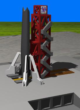
The above image is for a notional rocket / ramjet powered SSTO, hence the gaping hole where the nose should be. Our model will have a pointy nose.
Some mass models showing the disastrous mass growth effects from insisting upon HTHL, rather than the much lighter VTHL (because the landing gear and airframe don't have to support the takeoff weight of a fully laden vehicle), and why HTHL is likely not in our immediate future: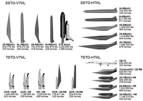
It's pretty clear to me that denser propellants really do make SSTO easier to achieve. I don't think solids would work, because the Isp is simply too low without truly absurd liftoff masses relative to the payload mass, but use of RP1 and LCH4 results in heavier but much smaller vehicles with reduced dry mass fractions. Dry mass equates to vehicle cost for airliners. Our vehicle is dramatically stronger and stiffer though.
LOX/RP1 is not exotic at all. Staged combustion is not frequently used for RP1, but it is presently used by both Russia and America thanks to the RD-180 engine, which means we have the know-how to use it. The airframe fiber is certainly expensive, but not all that exotic these days. T1100 fiber is finding more and more uses, and using it for an airliner wing spar is increasingly common. All major aerospace manufacturers use CFRP by the truckload. Boeing, Airbus, Lockheed-Martin, and Northrop-Grumman all have gigantic vacuum chamber autoclaves. The resin and resin curing process is definitely exotic, but not especially problematic with electric heating pads wrapped around the part. Tooling will not be cheap, that's for sure. The tank interior coatings are exotic. The primary TPS tile and leading edge materials are likewise expensive, but no longer particularly exotic within the realm of reusable space vehicles. All vehicles using tiles are now incorporating the latest tech.
What I see is a lot of materials and tooling costs, which have already been incurred for other aerospace programs, but not very many unknowns or basic technological barriers. The fibers, resins, and TPS materials are the "magic pixie dust" enablers here. ULA needs something useful to do, so they can run this project. Vulcan is not going to compete with Falcon 9, never mind Starship, and even they have stated as much. Boeing has the required autoclave equipment and know-how to work with very large monolithic composite structures. Northrop-Grumman works with exotic composites and resins, so maybe have them perform the layup work at Boeing's facility so Boeing can bake it in that giant oven? Maybe I'm wrong, but I don't think anyone else has a larger autoclave. Boeing built that monstrosity for Dreamliner fuselage baking. Someone who is not an aerospace prime needs to do the avionics / flight control software development and vehicle aero modeling / simulation, because our prime contractors' track records with this type of work is horrendous. Tesla should use their AI supercomputer tech to do the design and modeling. This vehicle is a complement to Starship, not a replacement for it. The engine design work should go to Barber-Nichols, followed by 3D printing by SpaceX or one of the other majors. NASA designs and fabricates the RCC nozzle. USAF or Sierra Nevada does the TPS work.
Boeing's DreamLifter is required for transport of the fuselage from the factory. NASA also has the barge to move the vehicle to the pad. Final assembly can take place at Michoud. The wings will have to be a separate transport. The only other possibility is using StratoLaunch, which may be required to transport the vehicle back to KSC unless NASA still operates the Space Shuttle transports. I think those were retired. This thing can only land at KSC or Edwards, just like the Space Shuttle.
Offline
Like button can go here
#4 2024-05-25 14:18:17
- kbd512
- Administrator
- Registered: 2015-01-02
- Posts: 8,518
Re: SSTO Airframe and TPS Materials
I've posted this before, but here it is again:
The Application of Carbon Fiber Composites in Cryo Tank
NASA / Boeing's 5.5m diameter composite cryogenic LH2 storage tank test article was fabricated from HexCel's HexTow IM7 fiber roving / tow, 12k filament count, impregnated with Syensqo Aerospace's CYCOM 5320-1 resin system, as a pre-preg (I think). 5320-1 resin is designed for out-of-autoclave curing / hardening. The layup over the mold was accomplished using a fully robotic tape laying machine (a giant robot arm with spindles of fiber attached to it, with the tank mold rotated while the arm holds and lays down the fiber over the mold, and then uses a laser to rapidly cure the resin as the fiber is layed down.
Alternating thick and thin plies of fiber tape were used to save fabrication time / money. It was noted by Boeing that the thin plies prevented micro-cracking and LH2 permeation of the tank walls, but NASA's project goal was to save both time and money fabricating the LH2 tank, as compared to Al-2195 fabrication, so both project goals were accomplished by using a sub-optimal (for tensile strength and cryogenic cracking resistance / LH2 permeation resistance) fiber laying scheme. The tank was 39% lighter than an equivalent Al-2195 tank while costing NASA 25% less than Al-2195 fabrication. It survived 50+ pressure cycles and LH2 permeation at end of testing was deemed acceptable.
Various documentation show that even with new robotic fiber laying methods and special resins that match the fiber's CTE and don't appreciably degrade with repeated exposure to LOX or LH2 and pressure cycling, there is no acceptable substitute for autoclave curing. The difference in density between autoclave cured composite and these modern methods is dramatic.
HexCel IM7 fiber is 820ksi tensile strength and modulus is 40Msi. Fiber diameter is 5.2µm
TorayCA T1200 fiber is 1,160ksi tensile strength and modulus is 46Msi. Fiber diameter is 5.0µm.
T1200 is 41% stronger and resists deformation 15% better than IM7.
IM7 composite tensile strength is listed as 400ksi. T1100G is 502ksi. T1200 composite should be about 573.7ksi.
That makes T1200 composite about 43.4% stronger than the IM7 composites from NASA's composite LH2 tank tests with our aerospace prime contractors. At the very least, said T1200 composite would be no less performant than IM7.
22,400ft^3 / 634m^3 LH2 Propellant Tank Weight
NASA Al-2195: 10,925lbs / 4,955.5kg (metals-based lightest tank mass using TRL9 metals)
Boeing Fluted Core: 6,696lbs / 3,037.3kg (38.7% reduction)
Lockheed-Martin External Box-Stiffened: 6572lbs / 2,981kg (39.8% reduction)
Northrop-Grumman Honeycomb Sandwich: 6,252lbs / 2,835.9kg (42.8% reduction)
Boeing's composite was vacuum-bagged, but not autoclave-cured. I can't speak to the fabrication methods used by the other technology demonstrators without documentation on them. Additionally, CYCOM 5320-1 was an experimental toughened pre-preg epoxy resin at that time. Said resin was touted as providing equivalent porosity to autoclave-curing and "competitive" mechanical properties (whatever that means), but I don't have proof of that (apart from it passing all tests). I don't consider that "good enough" to stake any claims on. PROOF Research resins, which require very high temperature autoclaving, have a growing body of actual testing backing them. Even so, I'm willing to consider that other cheaper / faster / easier to use resin systems may ultimately prove adequate if test results concur. LOX/RP1 requirements are a step below LH2 requirements, and cost is an ever-present issue.
So, how does the 10m tank weight estimate apply to our composite requirements?
For starters, the volume of the tank, multiplied by 3, exceeds the propellant volume plus 5% ullage volume, by 49m^3.
The 10m article was designed to withstand 3g launch loads and would hold 45,014kg of LH2.
The honeycomb core model, which is what I had in mind, is 6.3% of the propellant mass. Since T1200 fiber composite is 43.4% stronger than IM7, I should be able to get another 40% mass reduction, which implies 3.78% of the propellant mass. However, this is still too heavy, so our resin matrix needs single wall CNTs added to it, to increase its strength.
740,741kg of RP1 * 0.0378 = 28,000kg
1,259,259kg of LOX * 0.0378 = 47,600kg
CNT-enhanced composite tanks lighten rescue workers' loads
Graphene nanotube-enhanced composite tanks reduce weight in firefighters’ compressed air tanks by up to 75%, and show potential for hydrogen storage.
This SWCNT resin / matrix additive locks the layers of fiber together to prevent shear stress from delaminating the fiber plies within the composite, decreasing weight by 75% for a PET lined high pressure Oxygen tank intended for firefighters to store their O2 supply.
That means our RP1 tank weighs 7,000kg and our LOX tank weighs 11,900kg. We can live with that. This corresponds with 11.638m^3 of material to enclose 2,000t of propellant. Space Shuttle External Tank used 25,348kg (excludes insulation mass) or 9.388m^3 to enclose 2,050.798m^3 of propellant. So my T1200 composite material of choice provides 24% more material volume to work, it has 6.57X greater tensile strength, and more than double Al-2195's resistance to deformation under load. The entire inert dry mass fraction (55t) is about 2.75% of the propellant mass (2,000t). That leaves 7,636kg of material for the pressurized passenger compartment, thrust structure (will be integrated with the bottom of the LOX tank), wings, control surfaces, and landing gear.
Structural mass fraction, which engineers like to harp on, applies to the limit loads during each phase of flight. This thing isn't landing while it's filled with propellant. Upon landing, if 26,536kg of composite is applied to all structures, then this thing has a 29.5% structural mass fraction. Airliners have higher structural mass fractions because they have heavier engines and they land heavier and use greater quantities of structurally weaker metals. If these SSTO structures can survive ascent aero loads and reentry thermal loads, then they will surely survive landing with ease.
Falcon 9 boosters are primarily Al-2195 and they slam down on their rear ends after each flight. Those boosters have a 6.47% structural mass fraction. Using a T1200 composite that's 6.57X stronger than Al-2195, someone wants to tell me that we can't plausibly reduce our total dry stage mass fraction by 42.5%, which is how I arrived at a 2.75% dry mass fraction? That's before we add the CNT to the resin matrix to dramatically increase inter-ply adhesion / shear strength. This doesn't seem like a remarkable leap in technology, considering that Falcon 9 also uses LOX/RP1. Landing on a runway or on water skis is rather benign when compared to a Falcon 9 booster landing.
A Boeing 747 is mostly Aluminum by weight. It has a 49% structural mass fraction, so everything else is fuel or payload. The average strength of the materials used is about 60ksi to 70ksi. The average strength of T1200 composite is 572ksi, and stiffness is more than double that of Aluminum. Is a 20% structural mass fraction reduction really so remarkable using materials that have 8X+ greater tensile strength and 2X+ greater stiffness? Opinions clearly differ on this, but it seems to me like this really ought to work.
Put another way, with a 2.75% vs 6.47% dry mass fraction, our winged SSTO vehicle's propellant tank / fuselage structure is 3.78X stronger, pound-for-pound, when compared to a Falcon 9 booster. If a Falcon 9 booster is reusable for 100 flights before it's beat up too badly, then we should do no worse than that using a much stronger airframe.
Granted, all of this is "paper rocketry" without the detail level engineering analysis required to ensure that it does work, but back-of-napkin calculation should be able to tell us if our proposal remains within the realm of feasibility, or not. Maybe there are still problems with this, and detail level analysis will indicate that it's still infeasible.
Offline
Like button can go here
#5 2024-05-25 17:53:27
- SpaceNut
- Administrator
- From: New Hampshire
- Registered: 2004-07-22
- Posts: 30,634
Re: SSTO Airframe and TPS Materials
0https://en.wikipedia.org/wiki/Single-stage-to-orbit

https://en.wikipedia.org/wiki/Single-st … ission.tif

I notice that the yarn used is the same to what was used for the Adapt heatshield materials.
Offline
Like button can go here
#6 2024-05-25 20:29:12
- kbd512
- Administrator
- Registered: 2015-01-02
- Posts: 8,518
Re: SSTO Airframe and TPS Materials
SpaceNut,
I've already conceded that dropping off structural mass as you ascend to orbit is more efficient when payload mass is all that matters. This vehicle is not intended to compete with any TSTO, large or small, on payload mass fraction to orbit, per unit of structural weight, propellant weight, nor vehicle fabrication cost. As it pertains to fabrication costs, the rocket industry is slowly accepting that metals limit their options and do, in point of fact, cost more over time when all is said and done, due to the performance demanded of modern rocket powered vehicles. This SSTO is intended to produce less hardware to maintain or recover than a TSTO. The only realistically feasible "high value payload" that a SSTO should transport, is humans.
SSTO is a singular vehicle that (nominally) remains in one piece through the entire duration of its flight. It takes off like a rocket because it uses / requires rocket engines, primarily because no other kind of engine has the thrust-to-weight ratio demanded of a SSTO, and it lands on a runway like a glider because it has wings. The carriage of passengers makes sense as its singular use case because there are no hypersonic staging events and therefore nothing in close proximity to the vehicle to damage or destroy it during ascent, as happened twice with the Space Shuttle (once from the solid rocket boosters and once from the orbiter's external tank).
By tightly integrating every aspect of the vehicle's design, we can contain mass growth. Anything we learn from or new technology we develop to enable the designing, building, and operating of a SSTO can and will be directly applied to a TSTO. All of the new technology development carries over to TSTO. By learning how to build bleeding edge performance SSTOs, were are in effect learning how to build bleeding edge performance TSTOs. An extreme level of structural efficiency is the essence of SSTO, because structural efficiency is what makes it a good rocket powered vehicle. Well... TSTO is still a rocket powered vehicle, so the same applies to it as well. The beauty of SSTO design is in how something that would otherwise have lots of fiddly little parts added to it has been forcibly reduced down to something that is as simple as we can possibly make it, in order to do something as sophisticated as taking people to orbit.
If we wanted to select the most mass and energy efficient means of transporting people to work, that would probably involve walking or riding a bicycle. If time was another efficiency to consider, then we'd probably put them in buses or on trains, both of which are far less mass and energy efficient. If freedom of mobility was another important consideration, because only small numbers of them were headed to any one specific location, then we might put them in individual cars. In actual practice, we put a lot more people in their own car than on trains, specifically because many of them are headed to very different locations, at very different times, and all attempts at "better efficiency" are largely in vain without first considering other societal design elements that have little to do with buses vs trains vs cars.
If there's a place for cars in this world, and there clearly is, then there's a place for SSTO as well. After inefficiency killed the Concorde, enough people realized that we can do far better using modern materials, that now we have multiple supersonic transport startups.
This graph shows why there's renewed interest in supersonic flight:
Drag Coefficient vs Mach Number
If you can travel faster while burning less fuel, or merely achieve similar drag values as much slower aircraft, then you make your passengers happier by transporting them to their desired destination much faster, while also flying more efficiently in the process, thereby pleasing your accountants.
I want to determine how structurally efficient we can make our rocket plane. If it gets the job done for some nominal increase in propellant cost over a much more operationally complex vehicle, then it may still be worth the added propellant cost. If it takes a day or two to stack a Starship, but you can turn around and fly a SSTO within 24 hours, then that's a form of operational efficiency that any airline service would consider mandatory to merely consider purchasing and operating a plane. SSTO will require more maintenance than an ordinary jet airliner, because jet airliners don't ascent to orbit and reenter. The question is whether or not, relatively speaking, it's much simpler and faster to operate than a TSTO vehicle which requires stacking on the pad, evaluating any interstage damage from the staging event, and repairing or refurbishing the engines, electronics, and airframes on two separate vehicles.
At no point have I claimed that this will be easy or cheap to do. How relatively expensive it is has yet to be determined. The technology to do this simply was not available as recent as 10 years ago. Thus, this is a design experiment, first of its kind, as all new rocket technologies are. Even if it ultimately fails, any technology advancements can still be applied to extant or future TSTOs.
Offline
Like button can go here
#7 2024-05-26 08:00:22
- SpaceNut
- Administrator
- From: New Hampshire
- Registered: 2004-07-22
- Posts: 30,634
Re: SSTO Airframe and TPS Materials
Yes, with more dense fuels it makes the mass of launch less as we are not making a very large tank to hold LH2.
It also means that you are planning a ship that is smaller than a Falcon 9 heavy mass of 1,420,788 kg fully loaded ready for launch.
https://www.omnicalculator.com/physics/specific-impulse
There are 2 posts with content for SSTO.
Offline
Like button can go here
#8 2024-05-28 18:18:56
- SpaceNut
- Administrator
- From: New Hampshire
- Registered: 2004-07-22
- Posts: 30,634
Re: SSTO Airframe and TPS Materials
GW,
At no point in time has any claim been made that SSTO will beat TSTO on payload performance. That never was and will never be in the cards for SSTO. Basic physics says TSTO is superior for orbital launch. However, that is not the point behind SSTO. The point is to use a singular vehicle to send humans, and only humans, into orbit. For any kind of cargo, we will use TSTO or launch assist technologies (for low value materials such as water, gases, and metals). Human transport is the only plausible use case for spending more money, in order to reduce operational cost and complexity- not the complexity of designing or building a SSTO, but the actual operation of one high-performance rocket powered vehicle vs two, for the express purpose of creating an orbital passenger transport that operates similarly to an airline service.
Falcon 9 is a reusable booster with a 6.06% structural mass fraction for the booster stage. It's primarily Al-2195 alloy, which has a yield of 87ksi. T1200 fiber composite has a tensile / yield strength (basically the same thing) for CFRP, of 572ksi. To that, we're going to add SWCNT to the resin matrix. That bumps up yield / shear / buckling strength by about 75% for a given weight, because the CNT literally locks plies of fibers together by wrapping around them, like almost like a double-ended fish hook (what it looks like under a microscope), to the point that a high pressure CFRP PET-lined O2 tank for a firefighter that previously weighed 57lbs then became 6.1lbs for the same CFRP and PET liner, with the SWCNT resin matrix additive, for equivalent strength. The tank holds back the same pressure as a much thicker ordinary CFRP O2 tank, but it's drastically lighter because it's drastically stronger in every dimension.
If we built the Falcon 9's propellant tanks from T1200 composite, there is no reason I can think of as to why it absolutely must remain at or near the same weight as the Al-2195 propellant tanks. It will be both stiffer and stronger, by quite a lot, as compared to its metal-based counterpart. Al-2195 has 15% of the strength of a T1200 fiber composite, or 17.33% the strength of T1100 fiber composite (current technology for high-strength aerospace parts which are mass produced). T1100 fiber composite (the composite, not the fiber itself, which is 2X stronger than the composite) is both stronger and lighter than any metal alloy that is not more brittle than glass. Weaker but cheaper fibers such as T700, T800, and IM7 have been used by NASA and our primes for reducing weight and total fabrication cost, as compared to Al-2195. PROOF 900HT resin has a maximum wet service temperature of 288C, and is CTE-matched to the fiber, which is far more heat than Al-2195 can tolerate without becoming silly putty, with very little loss of tensile strength up to that temperature (somewhere between 10% and 20% loss of strength, but that only happens during reentry when the vehicle is much lighter, because the TPS provides quite a bit of thermal insulation during ascent). It cures at a much higher temperature than that (454C, IIRC), which is how and why I know that resin won't "go soft" (because you have to get it much hotter to cure it). This has been exhaustively tested by the US military for composite parts in close proximity to very hot jet engines. That is how and why we know that it works. It's been tested- a lot.
UltraMet makes 4.4lb/ft^3 toughened aerogel "Space Shuttle tiles", flown in space aboard the X-37 as part of its TPS package. A 243s exposure to 3,500F / 1,927C for a 1inch thick tile (0.367lbs/ft^2 / 3.3lbs/yd^2), resulted in a backside tile temperature of 350F / 177C at the end of the test. 177C is well below 288C (wet service limit for 900HT) or 350C (dry service limit for 900HT resin). Maximum Space Shuttle reentry temperature was 1,477C. Despite that fact, my mass estimate for TPS included RCC for the leading edges and UltraMet tiles everywhere else, even though lighter flexible fabric reusable surface insulation would suffice. NASA is actively developing BNNT and aerogel fabrics which are absurdly lighter than the flexible reusable fabric insulation used aboard the Space Shuttle.
When the composite strength is 572ksi, you're nowhere near the limit of its strength, your stiffness is more than double that of Al-2195, and the thickness of the composite (5.08mm) is more than double that of Aluminum, which means it's 16X as stiff, as compared to 2195. If Falcon 9's metals-based propellant tank structure doesn't provide that kind of strength, yet it's reusable, then how is a much stronger composite going to fail when its subjected to the same forces during ascent (when the vehicle is heaviest)? What I'm working on is, in point of fact, and despite greatly reduced weight, still far stronger than any equivalent metals-based structure. I've allocated more volume of material that is both stiffer and stronger. How is a Falcon 9 booster reusable when it cannot come anywhere near the strength and stiffness of a composite for equivalent weight? What mechanical properties does Al-2195 imbue the structure with?
My Delta-V with 2,000t of LOX/RP1 propellant, at 316s Isp, is 9,746m/s. The Isp of Oxygen-Rich Staged Combustion RP1 fueled engines, without vacuum nozzles, ranges between 311s and 338s, so I chose an Isp value modestly above sea level, since the vehicle won't remain at sea level for more than a handful of seconds. The majority of its ascent time will be spent substantially above sea level, where the engines produce more thrust per unit mass of propellant expended. I need RP1 engines with demonstrated Isp and a 200:1 thrust-to-weight ratio. That's already been achieved, plus a little extra. I'm not invoking any engine technology which hasn't already existed for quite some time now.
Everything that is not "engine" on the Falcon 9 booster weighs 21,370kg. The landing gear weigh about 2,000kg. By definition, the rest of that 19,370kg has to be propellant tank or thrust structure. It's 7.174 cubic meters of metal if it's primarily Al-2195. If it was made from HexCel IM7 fiber composite, then 7,361kg is a good guess as to how much it would weigh. If it was made from T1200 composite, then 2,906kg (no CNT resin additive) is a good guess as to how much it would weigh for equal strength.
25,600kg dry mass / (25,600kg + 395,700kg) = 6.08% dry mass fraction (as-built by SpaceX)
4,230kg + 7,361kg + 2,000kg = 13,591kg (new dry mass fraction with IM7 composite (as-built by Boeing / NASA)
13,591kg / (13,591kg + 395,700kg) = 3.32% dry mass fraction (IM7 / CYCOM 5320-1 resin)
4,230 + 2,906kg + 2,000kg = 9,136kg (new dry mass fraction with T1200 composite (no CNT additives)
9,136kg / (9,136kg + 395,700kg) = 2.26% dry mass fraction (T1200 composite)FYI, the IM7 composite, rather than bursting at 1.5X the pressurization load of the Al-2195 tank, burst at 277psi, which means it was absurdly over-built, but was absolutely guaranteed to pass all load tests. Every single one of these composite substitutes for Al-2195 has been overbuilt to the nth degree. Instead of asking why we're over-building composites 2X to 3X stronger than Aluminum (the reason they're not even cheaper), why isn't anybody asking what the logic is behind making the composites ridiculously stronger than any of the metal structures we routinely accept into service?
Boeing used a whole lot of fiber to avoid putting that tank into an autoclave. It could've been much thinner and lighter than it was, using the same IM7 fiber, with improved H2 permeability rates, had they used their giant autoclaves. Yes, it would take longer, no it probably would not be much cheaper than Al-2195 at that point, but performance is what makes the SLS useful, not saving a trivial amount of money relative to the entire project cost.
Anyway...
Would the landing gear still need to weigh 2t for a rocket stage with less than 1/2 of its original dry mass?
The kinetic energy absorbed by the landing gear is the product of mass and acceleration- ye olde F=ma. If the mass is half but vertical acceleration rate is the same, then you have half the kinetic energy. The vehicle is also dramatically "butt heavier", thanks to the engines and thrust structure now comprising almost 46% of the entire dry vehicle weight, so track width can be narrower for equivalent stability, which further reduces weight. We'll ignore that optimization and focus solely on weight added to make the gear strong enough.
8,136kg (gear now half as heavy, absorbing half as much energy on landing) / (8,136kg + 395,700kg) = 2.01% dry mass fraction
Would we be modestly "heavier than that" after accounting for our engine thrust structure and grid fins?
Yes, but not by a lot. That means a 2.75% dry mass fraction is achievable using 1,000ksi+ composites (T1200 fiber plus SWCNT resin matrix additive) and 200:1 thrust-to-weight ratio RP1 engines with a non-regeneratively cooled RCC nozzles plasma sprayed or CVD coated with UHTC, to prevent oxidation, as already proven to work and reduce weight and engine complexity by NASA engine testing with these nozzles.
The notional SSTO I have in mind is 4.31% payload and dry mass fraction. The 2,000t of propellant provides 9,746m/s of ΔV at 316s fixed Isp (reality is that Isp improves by a little bit more during ascent, up to 338s, 100bar chamber pressure). No aerospike, no nozzle extensions, etc. That should be enough to make up for drag and gravity losses.
To reiterate, I have completely conceded the point that a TSTO will outperform a SSTO, every single time. That is not "the why" behind building a SSTO. There are other factors at play beyond simple fuel cost and payload performance.
Can we also apply our same SSTO composite tech to TSTOs?
We obviously can, and we already have companies like Rocket Labs doing that with their LOX/RP1 TSTOs. We'd be foolish not to, assuming performance matters so much that we're de-justifying SSTOs on the basis of payload performance per unit of dry vehicle mass. It can't possibly be the cost of the composite tech, because we're using that more and more over time, regardless of SSTO vs TSTO. For me, this is more about advancing rocket tech than whether or not a SSTO can deliver more payload than a TSTO. The answer to that question is beyond obvious.
I want to roll our best composite tech, best engine tech, best thermal protection system tech, and best avionics / life support / power / thermal management tech into a single vehicle, to show the entire world what "the best" actually looks like and how astonishing the end result is- something previously thought impossible actually is possible with modern materials. Whether or not it's practical is a different question.
Offline
Like button can go here
#9 2024-05-28 18:20:49
- SpaceNut
- Administrator
- From: New Hampshire
- Registered: 2004-07-22
- Posts: 30,634
Re: SSTO Airframe and TPS Materials
I'm old and obsolete, but in my days there were no materials that even came close to 572 ksi tensile strength, and there were no organic matrix composites that could withstand steady service temperatures above 300 F. The highest strength steels back then were in the 280 ksi class, and all the then-known composites no better than mild steel. The best organic bound material we had available was asbestos-epoxy, and it became junk at 290 F. You had to trowel it on thick, to meet burn time (2-10 sec) as a protectant inside rocket motors.
Let's just say I am an open-minded skeptic about such material claims, especially given the way corporations out-and-out lie in their advertising hype. They will say literally anything to make sales, especially to the government. I saw that happen for decades in the defense industry.
The point of my bounding calculations was to show that getting 9.3 km/s out of a single stage was possible with Isp in the low to mid 400 sec range, but not possible in the low-to-mid 300 sec range. It is possible in the high 300-sec range, but you have very little inert+payload allowance left over. Too low to be in the least credible. Not when the indicated propellant mass fraction is 88+ %, and above 90% as the Isp drops. 100 minus that propellant percentage is all the allowance you have! Your inert and payload fractions have to fit within that. And bear in mind that something surviving one entry is still a hell of a long way from providing a long useful service life!
Entry isn't a single temperature at this-or-that location. It is literally a heat balance among some 5 items, not all of which are present in any given scenario. Consider this: at around Mach 10-to-12 around 50 km up, most shallow-angle entry vehicles are close to, or in, max heating. Depending upon shape and ballistic coefficient, that convective heating rate can be anywhere in the range of 300-3000 W/sq.cm.
It's a short pulse, only several seconds long, but it is several seconds long! It will not be equilibrium, but an equilibrium model is a decent guide to what you have to fight. And a rough guide to the effective driving temperature of the plasma in the sheath about that vehicle is in the range of 3300-4000 K.
If that balance is not achieved, the material is going to soak out locally to that driving temperature, much faster than conduction or convection inward to a heat sink can possibly occur. Your only real, demonstrated, cooling options are high-temperature re-radiation or fast ablation, right from the heated surface. Transpiration cooling analyzes as possibly a good third candidate, but has never actually yet been flown to verify that claim.
I'm not saying that an SSTO few-people-only mover to LEO is impossible. I'm just saying it won't be very attractive, and the design space is very limited indeed. You'd be better off with a TSTO and a few people in a simple capsule. Something we already know works. With a wide range of design options available.
GW
Offline
Like button can go here
#10 2024-05-30 13:32:59
- kbd512
- Administrator
- Registered: 2015-01-02
- Posts: 8,518
Re: SSTO Airframe and TPS Materials
There seems to be a belief that composites cannot be made light enough to ensure reusability. Composites don't behave as metals do. With any metal structure, to ensure reusability you're trying to remain within a specific portion of the stress-strain curve to prevent cracking from fatigue (the metal flexing back-and-forth with pressurization and aero loads), or more often in the case of very thin metal structures like rocket propellant tanks, plastic deformation leading to failure. Composites typically don't fail because the fiber itself was over-stressed. The high strength / intermediate modulus fiber itself typically has 800ksi to 1,000ksi+ of tensile strength. There is no metal nor metal alloy that has that kind of tensile strength, never mind an alloy with a density of only 1.8g/cm^3. Certain steel or Tungsten alloys may approach 500ksi, but they're as brittle as glass. Unfortunately, the resin matrix is much weaker, and its density falls between 1g/cm^3 to 1.5g/cm^3. In a typical high-fiber-fill unidirectional tape layup with plies of fiber laid up in different orientations to ensure strength in multiple directions, there is a 60% fiber fill and 40% resin matrix fill.
Composites do fail in a propellant tank or wing application, for the following reasons:
1. Buckling of the fiber within the resin matrix. The strength of the fiber is directional. If you try to "pull" strands of the fiber apart, you're going to find that exceptionally difficult to do.
2. Inter-laminar shear stress causing plies of fiber to delaminate from the composite.
3. Strain causing enough deflection / deformation under load to initiate microcracking in the case of cryogenic propellant tanks, especially for LH2 propellant tanks, whereupon Hydrogen starts to permeate the resin matrix.
4. Aerothermal loads become so great, such as during the heating which occurs during reentry, that the resin matrix softens, the fibers start to move within the matrix or plies delaminate, and then the composite fails. This applies to resins with low glass transition temperatures and composites with no thermal protection. There are resins with very high glass transition temperatures, relative to most other plastics. All reentry vehicles use special materials to greatly inhibit the rate of heat transfer and/or re-radiate the heat.
5. Chemicals oxidize or reduce the resin matrix, as would be the case with LOX and LH2. We have resins that are highly resistant to either, but not both at the same time, so far as I know.
This is what's important:
1. Fibers are laid up in different orientations to prove near-uniform strength in the expected planes that loads will be applied in, somewhat similar to a metal. For a composite propellant tank, this implies at least two layers with the fibers in a ply of tape or fabric running 90 degrees to each other, but more often there are plies every with 15 to 30 degree orientations. You can think of them as a series of very thin stacked plates with extreme strength in one direction.
2. The resin-to-fiber ratio must remain highly uniform throughout the structure being laid up, and gaps between layers must be minimized, because the fiber is what makes the structure strong, not the resin. Minimizing excessive gaps between the fibers and toughening the resin with an even thinner material such as short strands of CNT or Graphene flakes locks the fibers into the matrix and prevents inter-laminal shear stress from delaminating plies of tape or fabric.
3. The stiffness of a standard modulus high tensile strength CFRP is nothing to write home about. This is one of the major problems. You may not be able to physically pull the structure apart, but if the strain is high enough to cause sufficient deformation or deflection under load for the fibers to pull away from the resin matrix, then this is what will actually cause the structure to fail.
This is what I actually worry about with composites. The fiber itself is more than strong enough to withstand repeated extreme loads. So long as you can keep the matrix from deflecting enough to crack or for the fibers to pull away, the fact that it's under sufficient load to cause all metals to fail isn't that relevant. Essentially, even though it's technically a "strength problem" with the resin matrix, it's actually a "stiffness problem" with the geometry of the structure. This is good, because we can use geometry to impart the required stiffness to immobilize the fibers at the expected strain.
The "solution", such as it were, isn't to "make the structure stronger", so much as "make it stiffer" or more rigid, so that strain is kept low enough while it flexes under load, that it flexes very little, and thus will not crack or delaminate.
There are no set number of load cycles that CFRP can be subjected to at a given level of stress (below the failure point, obviously), which is quite unlike metal. So long as the fiber remains sufficiently immobilized within the resin matrix, using geometry or siffeners rather than piling on enough layers of tape to "make it stronger", it can be repeatedly stressed to its maximum allowable strain until the cows come home, and it's not going to break or otherwise "wear out".
NASA determined through actual testing in a LH2 environment, that allowable strain (deflection or deformation under load) was 5000 micro inches per inch. That much strain was allowable, and there would be no formation of microcracks, even with repeated mechanical loading while containing LH2. This testing involved hundreds of cycles. Propellant tanks built to that standard were approximately 40% lighter than Al-2195 equivalents. Additionally, to save money, they used thicker plies of IM7 tape which were known to make the structure weaker and heavier, but so long as they all hit the weight and cost targets, NASA didn't care. For a fully reusable SSTO, we wouldn't care about extra layup time. It took Boeing / Lockheed-Martin / Northrop-Grumman about a month to fabricate their very large LH2 tank test articles. So what if it took 2 months? Is that an acceptable amount of airframe build time for a fully reusable SSTO vehicle that will be used for many years? I think so. We're not mass producing airliners or fighter jets. We're building 12 to 36 vehicles. Bespoke production methods for that quantity of vehicles is perfectly acceptable by my way of thinking.
The Kevlar49 composite COPVs used aboard the Space Shuttle would ultimately fail around 1,300,000 cycles. I've never heard of an airliner or spacecraft completing a million flights before retirement, so we would generally consider a million pressurization cycles to be perfectly acceptable service life, even if we're doing lots of testing on the ground.
Offline
Like button can go here
#11 2024-06-02 11:30:27
- SpaceNut
- Administrator
- From: New Hampshire
- Registered: 2004-07-22
- Posts: 30,634
Re: SSTO Airframe and TPS Materials
I’m unsure where to post this. It and some of the preceding posts may well belong somewhere in the new SSTO topic.
Composite materials are tricky, and the advertising hype about them is very, very misleading.
The advertised high strengths are always ONLY in the fiber lay direction! Strength in the other directions is very much lower, and can be near-zero out of the fiber plane, depending essentially only upon the matrix properties. You have to “play God” and know all the necessary fiber lay directions to handle all the loads your structure might ever encounter. The odds of actually doing that successfully, first time up in a new design, are actually quite low.
These composite materials have strength only in the direction of the fiber lay, and even then ONLY so long as the matrix holds them in place! If the matrix fails for any reason at all, your material essentially turns into loose rags or threads or yarns. You can get strength in two directions, for some variable-with-angle level of strength in-plane, by using real woven cloth as your fiber.
The strength between two layers of fiber laid in different directions, or two layers of woven cloth oriented differently, is ONLY that of the matrix gluing them together, which is usually down in the 5-10 ksi range, and even then usually only by shear! If your stresses are 3-D, the material will fail at very low stress levels, in precisely the direction where fibers do not lay. It is inherent.
There is no practical way around that, other than fully-3-D fiber preforms, the manufacture of which is extremely difficult and horribly expensive. And the infiltration of those 3-D preforms with a matrix is also extremely difficult and horribly expensive! This is usually only done with metal matrix composites.
The tightly-woven tapes in particular are very strong in the long direction, when used in composite work. But if you try to use that by itself, in multiple layers of spiral wrap in alternating directions to make a cylindrical vessel, the only thing connecting one strip of tape to the next is matrix shear, with a low shear-bearing area from one tape strip to the next tape strip! Pressure test results of the vessel will be extremely disappointing! You might have considerable hoop strength, but you will inherently have almost zero longitudinal strength, and you will have essentially no bending strength as a tubular bending-loads-resisting structure (as in a cylindrical tank that is also an airframe component). These are best made with a few layers of woven fabrics, or many, many layers of yarn spin-wrapped in multiple different directions.
You cannot use composites, especially woven composites, in arbitrarily thin layers! The thinnest thickness of a one-layer woven cloth composite is the thickness of that cloth layer. Period. Set by the threads or yarns from which it was woven, but a bit larger due to the weave geometry. You are extremely unlikely to get the strengths you need, unless there are actually multiple layers with different fiber lay directions! This stuff simply cannot be arbitrarily thin! Formable metals can be arbitrarily thin, except that alpha-phase titanium cannot, only beta phase titanium can be formed into thin sheet (which ages at room temperature into uselessness, with big, weakly-bound grains).
The ceramic and carbon fibers that are now popular are indeed “good” for substantial exposure temperatures, by themselves. Generally speaking, the organic polymer matrices you must use with them are not! Most of the hydrocarbon-type polymers start charring at around 300-400 F, and even the silicones start charring at about 600 F.
Everything organic or silicone is fully carbonized by no more than 1000 F, into something soft and crumbly, resembling the charcoal in your BBQ grill, except that it may still be reinforced by the fibers, but only if those fibers were ceramic or carbon. That is not a particularly reusable material for heat exposures, but if the charcoal “hangs together” better with the fiber reinforcement, the hype can truthfully claim their material “survived” the exposure, as long as NOT A WORD was said about ever using it again!
None of the polymers, or other plastics that I have ever heard of, have more than utterly-trivial elongation capability soaked out cryogenically cold (way under 1%). Using such materials in composite cryogenic propellant tanks thus presents two extremely serious problems: (1) very brittle behavior conferring extreme fragility in any kind of handling, and (2) leakage of propellant through the inherent porosity of the composite, unless you can successfully add some sort of internal sealing layer (not a trivial exercise in and of itself).
Taken together, those cryo-cold fragility troubles, the weight of multiple fabric layers to get strength in more than one direction, and the inability to sustain high temperature exposures, plus the manufacturing costs, are EXACTLY why SpaceX abandoned its original composites-construction concept for its Starship, in favor of simply welding-up 300-series stainless steel sheets!
Not having to put a heat shield on the lee side surfaces with stainless steel saves a great deal of heat shield weight, and also saves some rather large manufacturing costs, which made stainless steel the far better choice for a stage that must also qualify as a re-entry vehicle from orbit, plus endure descent and landing loads. You can take 304/304L SS to 1200 F as many times as you like, although it will start corroding and scaling if you let it get any hotter than that. Nothing re-radiates efficiently enough for self-cooling until it reaches temperatures in that 1000-1200 F class. Organic-matrix composites never will survive that exposure, and still be usable a second time.
There is also the issue of stiffness, which is partly the moment of inertia of the geometry, and partly the modulus of elasticity of the material. Steels have a modulus of elasticity in the 30 million psi range. Aluminum is about 10 million psi. Carbon-epoxy gets close to aluminum, and the other things like glass-vinyl ester (or glass-polyester) are far less stiff than that. Even Kevlar-vinyl ester, while quite tough against impacts and punctures, is far less stiff. Depending upon what the structure has to do, the achievable stiffness may (or may not) be crucial. But carbon-epoxy (and the others I mentioned) is limited to under about 300 F exposure, if the epoxy matrix is to survive in a reusable condition!
And then there is detection of impact damage, to which any composite is critically vulnerable. Unless of catastrophic magnitude, it’s often hidden damage, you see nothing on the surface. Ignoring the advertising hype otherwise, the only way known to reliably detect hidden damage is by comparing before and after x-ray images, looking for differences. There has to be one taken before the impact, and the other after, for this to work.
Every square inch of the composite has to be in an as-built x-ray somewhere, so that after a suspected impact, a post-impact x-ray can be taken for direct comparison to the as-built x-ray. The advertising hype is wrong, there are NO general criteria for evaluating post-impact x-rays only! Nothing is reliable enough to permit that! These materials are simply too variable from one square inch to another, to permit that sort of thing. This requirement for as-built x-rays during manufacture acts to further drive-up costs.
There is also the question of joints. Everyone is familiar with the way the fiberglass fenders on a Corvette eventually tear out around the machine screws holding them in place. You simply cannot attach composite parts to other structures that way, it is not reliable, and it won’t last, especially if highly-loaded. Fiberglass or something else, it does not matter! Composites and conventional fasteners are simply incompatible.
What is required is a hybrid of alternating layers of the composite and shim-stock thin metal, with enough layer bond area to carry the loads by only matrix shear, from the metal layers holding the fasteners, into the composite layers that extend into the rest of the composite structure. There must be enough layers of the metal shim material to take the fastener loads as bearing loads without failing, which in turn means there must also be many layers of composite, in the region of the joint.
That’s very labor intensive (and therefore expensive) to accomplish, which is EXACTLY why I do not trust Boeing to have done that job correctly on the B-787. Neither do I trust Airbus to have done this job correctly, not after that Airbus lost its composite vertical fin and crashed in NYC many years ago. The fin tore out around the bolts holding it to the aluminum airframe (it was not a hybrid joint, surprise, surprise). But this hybrid technique worked like a charm with composite solid rocket motor cases and metal end closures, up to 4-5000 psi, as tested and well-proven.
If you get the idea that designing and building with these materials is difficult, and fraught with fatal pitfalls, then you understand the main point here. If you do this job wrong, you will achieve better weight reductions and more cost savings (although still more expensive than metal construction). However, the product WILL INEVITABLY FAIL unexpectedly in service, causing very serious and expensive legal issues of the “whose fault was this?” type. Such can be quite catastrophic.
On the other hand, if you do the design correctly, and avoid those unexpected failures in service, your product will cost even more, and it will save only a little weight, compared to equivalent metal construction. Top managers hate that. Rightly or wrongly (wrongly in my opinion), they tend to discount the legal troubles for unexpected failures in service, and will push you very hard to do the job wrong. (Which in turn is partly why the advertising hype lies so egregiously.)
I’m probably obsolete and out-of-date, regarding all the latest composite materials. But none of these older ones (or the new ones I am not familiar with) will have any different extreme directionality of their properties, or any different severe limitations on exposure temperatures for their organic matrices (including the silicones). And the metal matrix composites are still horribly expensive, and probably always will be. As well as exceedingly difficult to manufacture.
There are no “magic” materials!
GW
Offline
Like button can go here
#12 2024-06-02 14:21:35
- kbd512
- Administrator
- Registered: 2015-01-02
- Posts: 8,518
Re: SSTO Airframe and TPS Materials
I’m unsure where to post this. It and some of the preceding posts may well belong somewhere in the new SSTO topic.
Composite materials are tricky, and the advertising hype about them is very, very misleading.
Misleading to who?
Were all the B-2s, F-22s, F-35s, Boeing 777s and 787s, Airbus A380s and A350s, all "built incorrectly" because they were largely made from composites?
None of those planes have fallen out of the sky due to the materials they were built from. They've had engines explode, steel shear bolts that were not properly torqued, maintenance on hydraulic systems ignored, and egregious computer software and sensor issues, but by and large almost every single one of them were brought down by pilot error or misunderstanding.
I would wager that most modern aerospace vehicles not brought down by their own overly-complex software and sensors will be brought down through operator error. Even the Boeing 737 Max aircraft that were brought down were on autopilot (during takeoff and landing sequences). If you cannot hand-fly the plane during the most critical phases of flight, then maybe you shouldn't be a pilot!
The advertised high strengths are always ONLY in the fiber lay direction! Strength in the other directions is very much lower, and can be near-zero out of the fiber plane, depending essentially only upon the matrix properties. You have to “play God” and know all the necessary fiber lay directions to handle all the loads your structure might ever encounter. The odds of actually doing that successfully, first time up in a new design, are actually quite low.
That is why fiber is laid in multiple directions. The engineers who design these structures are not "playing God". They're using known materials properties and test data from actual testing to determine what works, what doesn't, and why. Using materials to reduce weight is not indicative of "having a God complex", it's using what you have and what you know to meet design requirements.
These composite materials have strength only in the direction of the fiber lay, and even then ONLY so long as the matrix holds them in place! If the matrix fails for any reason at all, your material essentially turns into loose rags or threads or yarns. You can get strength in two directions, for some variable-with-angle level of strength in-plane, by using real woven cloth as your fiber.
See above.
The strength between two layers of fiber laid in different directions, or two layers of woven cloth oriented differently, is ONLY that of the matrix gluing them together, which is usually down in the 5-10 ksi range, and even then usually only by shear! If your stresses are 3-D, the material will fail at very low stress levels, in precisely the direction where fibers do not lay. It is inherent.
Every composite fuselage and wing airliner, and certainly every modern fighter jet in existence, would've fallen out of the sky already if the materials used were incapable of withstanding the stresses applied. Since they don't, the simplest conclusion to come to is that the materials and fabrication methods used are both up to snuff.
There is no practical way around that, other than fully-3-D fiber preforms, the manufacture of which is extremely difficult and horribly expensive. And the infiltration of those 3-D preforms with a matrix is also extremely difficult and horribly expensive! This is usually only done with metal matrix composites.
If this was an actual problem, we'd know about it by now. We'd have airliner wings coming off mid-flight, the fuselage would burst from the pressure applied to it, and every diver or fire fighter's SCBA tank would explode... But that hasn't happened. Composites are used with increasing frequency because at least some people accept that uniform strength in all directions is not required at all times for all applications.
The tightly-woven tapes in particular are very strong in the long direction, when used in composite work. But if you try to use that by itself, in multiple layers of spiral wrap in alternating directions to make a cylindrical vessel, the only thing connecting one strip of tape to the next is matrix shear, with a low shear-bearing area from one tape strip to the next tape strip! Pressure test results of the vessel will be extremely disappointing! You might have considerable hoop strength, but you will inherently have almost zero longitudinal strength, and you will have essentially no bending strength as a tubular bending-loads-resisting structure (as in a cylindrical tank that is also an airframe component). These are best made with a few layers of woven fabrics, or many, many layers of yarn spin-wrapped in multiple different directions.
Pressure tests in an actual IM7 fiber composite LH2 tank, after being subjected to 100 pressurization cycles, resulted in a bursting pressure of 277psi. The Aluminum tank, which was about 50% heavier than the composite tank, failed around 46psi, just as it was designed to do. Every contractor on that project made absolutely certain that their tank design wouldn't fail until it had at least met specifications. I would say that the pressure test results were extremely encouraging, given than no Aluminum tank of equivalent weight will ever be nearly as strong, and in point of fact wasn't, as determined by actual testing.
You cannot use composites, especially woven composites, in arbitrarily thin layers! The thinnest thickness of a one-layer woven cloth composite is the thickness of that cloth layer. Period. Set by the threads or yarns from which it was woven, but a bit larger due to the weave geometry. You are extremely unlikely to get the strengths you need, unless there are actually multiple layers with different fiber lay directions! This stuff simply cannot be arbitrarily thin! Formable metals can be arbitrarily thin, except that alpha-phase titanium cannot, only beta phase titanium can be formed into thin sheet (which ages at room temperature into uselessness, with big, weakly-bound grains).
Good to know, but nobody making propellant tanks or high pressure COPVs or SCBA tanks is actually using woven fabric composites. What relevance does something that nobody is actually doing have to what I am actually talking about doing? It's not a rhetorical question. What in the heck does this have to do with winding fiber tape around a mold?
In other posts, if you read what I wrote, I specifically stated that there won't be a single ounce of Titanium in this design. Everything will be a composite of the tape wound variety, a ceramic composite, or a high strength steel with composite tape wound overwrap.
The ceramic and carbon fibers that are now popular are indeed “good” for substantial exposure temperatures, by themselves. Generally speaking, the organic polymer matrices you must use with them are not! Most of the hydrocarbon-type polymers start charring at around 300-400 F, and even the silicones start charring at about 600 F.
If temperature resistance was an actual problem, then all the composites surrounding the jet engines of modern fighter jets would fail, but they don't because they have the temperature resistance required. If we once again go back to what I actually stated, we are going to have a very substantial thermal protection system applied to the entire vehicle, because that does not increase dry mass of the vehicle to the point where it poses a problem. The actual temperatures will remain very comfortably below, as in 200 degrees or more lower, than what the resin matrix can tolerate.
Everything organic or silicone is fully carbonized by no more than 1000 F, into something soft and crumbly, resembling the charcoal in your BBQ grill, except that it may still be reinforced by the fibers, but only if those fibers were ceramic or carbon. That is not a particularly reusable material for heat exposures, but if the charcoal “hangs together” better with the fiber reinforcement, the hype can truthfully claim their material “survived” the exposure, as long as NOT A WORD was said about ever using it again!
Duly noted. Nobody is talking about going anywhere near the temperature range you're concerned about. If this thing was made from Aluminum, then it would still fail at the same temperature range that modern composites and resins fail at. The TPS has to remain intact to survive reentry.
None of the polymers, or other plastics that I have ever heard of, have more than utterly-trivial elongation capability soaked out cryogenically cold (way under 1%). Using such materials in composite cryogenic propellant tanks thus presents two extremely serious problems: (1) very brittle behavior conferring extreme fragility in any kind of handling, and (2) leakage of propellant through the inherent porosity of the composite, unless you can successfully add some sort of internal sealing layer (not a trivial exercise in and of itself).
Well, we're not going to be dropping the propellant tanks while they're cryogenically cold, so I'm not sure what kind of handling you're thinking about, but once the vehicle is filled with propellants it's headed into space, not a crash derby. The porosity issue applies to thick lamina with more resin between them, it applies to LH2, but I'm talking about using LOX and RP1. It would be nice if we all quit fixating on a propellant that makes the dry vehicle mass fraction much too high to provide half as much payload for the same dry vehicle mass fraction.
Taken together, those cryo-cold fragility troubles, the weight of multiple fabric layers to get strength in more than one direction, and the inability to sustain high temperature exposures, plus the manufacturing costs, are EXACTLY why SpaceX abandoned its original composites-construction concept for its Starship, in favor of simply welding-up 300-series stainless steel sheets!
SpaceX abandoned composites because they cost more money. Elon Musk said so himself. He asserted, without evidence, that stainless is stronger than composites. How he came to that conclusion is not known to anyone, and flies in the face of actual testing. He was worried about the cost of the TPS, yet Starship now has almost every square inch covered in TPS tiles!
Not having to put a heat shield on the lee side surfaces with stainless steel saves a great deal of heat shield weight, and also saves some rather large manufacturing costs, which made stainless steel the far better choice for a stage that must also qualify as a re-entry vehicle from orbit, plus endure descent and landing loads. You can take 304/304L SS to 1200 F as many times as you like, although it will start corroding and scaling if you let it get any hotter than that. Nothing re-radiates efficiently enough for self-cooling until it reaches temperatures in that 1000-1200 F class. Organic-matrix composites never will survive that exposure, and still be usable a second time.
There is no stainless steel alloy on this planet which will be lighter than a composite plus modern TPS tile technology. The steel itself exceeds the weight of a composite and TPS tile solution which provides adequate protection.
There is also the issue of stiffness, which is partly the moment of inertia of the geometry, and partly the modulus of elasticity of the material. Steels have a modulus of elasticity in the 30 million psi range. Aluminum is about 10 million psi. Carbon-epoxy gets close to aluminum, and the other things like glass-vinyl ester (or glass-polyester) are far less stiff than that. Even Kevlar-vinyl ester, while quite tough against impacts and punctures, is far less stiff. Depending upon what the structure has to do, the achievable stiffness may (or may not) be crucial. But carbon-epoxy (and the others I mentioned) is limited to under about 300 F exposure, if the epoxy matrix is to survive in a reusable condition!
Finally, an actual issue to discuss. The modulus of elasticity of the actual composite is more than double that of Aluminum, but only about as good as steel. Nobody is talking about using glass fiber, so again, why bring up something not germane to what is actually being proposed here? It's interesting errata, but not relevant to the proposal. Once again, the temperature under the tiles will be far below what the resin matrix itself can tolerate. With 3 inch thick tiles, it'll remain below the point point of water.
And then there is detection of impact damage, to which any composite is critically vulnerable. Unless of catastrophic magnitude, it’s often hidden damage, you see nothing on the surface. Ignoring the advertising hype otherwise, the only way known to reliably detect hidden damage is by comparing before and after x-ray images, looking for differences. There has to be one taken before the impact, and the other after, for this to work.
The TPS tiles are equally vulnerable to impact damage. SpaceX's stainless steel Starship is STILL relying upon those materials.
Every square inch of the composite has to be in an as-built x-ray somewhere, so that after a suspected impact, a post-impact x-ray can be taken for direct comparison to the as-built x-ray. The advertising hype is wrong, there are NO general criteria for evaluating post-impact x-rays only! Nothing is reliable enough to permit that! These materials are simply too variable from one square inch to another, to permit that sort of thing. This requirement for as-built x-rays during manufacture acts to further drive-up costs.
Okay. So, we will take as-built X-rays of the structure. That is not a particularly length process.
There is also the question of joints. Everyone is familiar with the way the fiberglass fenders on a Corvette eventually tear out around the machine screws holding them in place. You simply cannot attach composite parts to other structures that way, it is not reliable, and it won’t last, especially if highly-loaded. Fiberglass or something else, it does not matter! Composites and conventional fasteners are simply incompatible.
The LH2 test tanks did have fasteners in the form of fore and aft "manhole covers". They were not particularly problematic. The joints between different parts of the tanks, did present more of an issue, and all contractors involved devised their own solutions to those problems, and all of them passed the battery of tests they were subjected to.
What is required is a hybrid of alternating layers of the composite and shim-stock thin metal, with enough layer bond area to carry the loads by only matrix shear, from the metal layers holding the fasteners, into the composite layers that extend into the rest of the composite structure. There must be enough layers of the metal shim material to take the fastener loads as bearing loads without failing, which in turn means there must also be many layers of composite, in the region of the joint.
Very thin layers of stainless steel foil have been bound into tape wound lamina to do exactly that, and the contractors NASA used did in fact build-up layers around those joints, almost as if they were aware of these potential problems and accounted for them.
That’s very labor intensive (and therefore expensive) to accomplish, which is EXACTLY why I do not trust Boeing to have done that job correctly on the B-787. Neither do I trust Airbus to have done this job correctly, not after that Airbus lost its composite vertical fin and crashed in NYC many years ago. The fin tore out around the bolts holding it to the aluminum airframe (it was not a hybrid joint, surprise, surprise). But this hybrid technique worked like a charm with composite solid rocket motor cases and metal end closures, up to 4-5000 psi, as tested and well-proven.
We don't really trust Boeing to do the job right. There's something we both agree on. So, if the wound composite rocket motor casings can tolerate pressures that only much much heavier steel forgings can tolerate, isn't that a form of proof that composites can and do work, if manufactured correctly?
If you get the idea that designing and building with these materials is difficult, and fraught with fatal pitfalls, then you understand the main point here. If you do this job wrong, you will achieve better weight reductions and more cost savings (although still more expensive than metal construction). However, the product WILL INEVITABLY FAIL unexpectedly in service, causing very serious and expensive legal issues of the “whose fault was this?” type. Such can be quite catastrophic..
Lots of metal parts can and do inevitably fail unexpectedly in service. If the failure was expected, then it would've been accounted for. The metallic Space Shuttle airframe "failed unexpectedly" after its TPS "failed unexpectedly". Short of making a spacecraft from Tungsten, which itself imposes numerous design problems, any aerospace vehicle can fail, and virtually all of them have, regardless of what they were made from.
On the other hand, if you do the design correctly, and avoid those unexpected failures in service, your product will cost even more, and it will save only a little weight, compared to equivalent metal construction. Top managers hate that. Rightly or wrongly (wrongly in my opinion), they tend to discount the legal troubles for unexpected failures in service, and will push you very hard to do the job wrong. (Which in turn is partly why the advertising hype lies so egregiously.)
40% lighter than Aluminum is not "only a little weight". It's quite a lot. A 57lb CFRP SCBA tank vs a 6.1lb CFRP SCBA tank designed to hold highly pressurized O2 or H2 is not a little bit of weight, it's a lot.
I’m probably obsolete and out-of-date, regarding all the latest composite materials. But none of these older ones (or the new ones I am not familiar with) will have any different extreme directionality of their properties, or any different severe limitations on exposure temperatures for their organic matrices (including the silicones). And the metal matrix composites are still horribly expensive, and probably always will be. As well as exceedingly difficult to manufacture.
Some of the issues you brought up would be perfectly valid engineering concerns 30 years ago. The great thing about accumulating knowledge and experience is that it accumulates over time. We now know what not to do. All the things you mentioned were things that NASA's document about their cryogenic LH2 tank specifically called out as testing points which were repeatedly tested. However slowly, however painfully, it's almost as if the engineers involved learned over time.
There are no “magic” materials!
GW
Agreed!
Offline
Like button can go here
#13 2024-06-02 16:37:51
- GW Johnson
- Member
- From: McGregor, Texas USA
- Registered: 2011-12-04
- Posts: 6,174
- Website
Re: SSTO Airframe and TPS Materials
I never said you couldn't make a spacecraft structure out of composite. I just said it's tricky. It was tricky 30+ years ago, and it is still tricky today. However, that being said, I still do NOT believe the claimed large weight savings. That crap was erroneous 30+ years ago, and the basic issue is still pretty much the same today. There are still NO effective truth-in-advertising laws! Use that marketeer-claimed crap at your peril. Which is EXACTLY why I still do not NOT believe in any "572 ksi strength". Of anything.
Heat protection during entry is still wildly-misunderstood by most folks. There are lots of ceramics today that can stand the equilibrium re-radiation temperatures incurred during re-entry from low Earth orbit. (Entry from a higher-energy orbit is still an open question). The problem is equilibrium heat transfer among multiple phenomena: you need a layer of very low thermal conductivity underneath your outer ceramic layer, in order to cut off the conduction into the interior. Otherwise, the substrate is going to get very hot (too hot for aluminum, too hot for composites, maybe too hot for for SS or other super-alloys). Maybe not. The "Starship" heatshield still has yet to prove itself in its current form!
That balance is why the Shuttle used low-density and structurally-weak ceramic tiles. Except not in or near stagnation zones, where they used the slow ablative carbon-carbon composite (expensive, and brittle enough to be fragile, as demonstrated by the loss of Columbia). The newer TufRoc tiles on X-37B are actually two-layer items: the denser outer layer is good to even stagnation equilibrium entry temperatures, and the lower density (and weaker!!!) ceramic underneath is the low thermal conductivity layer that stops the conduction of heat into the airframe structure underneath.
That stagnation heating is mass-at-entry-dependent, of course. These TufRoc things are still bonded to the airframe as two-layer tiles, which is still a single-point failure mode. They haven't lost one yet to a failure, but they still might! And bigger entry mass is bigger ballistic coefficient, which is bigger stagnation heating, all else being equal (including effective "nose" radius!!!!). The crude "governing" equation for stagnation convective heating is quite empirical: q = Q/A = constant*[(atm density/nose radius)^0.5]*[speed ^ 3]. That simple idiocy has held up remarkably well as a low circular orbit entry estimate since 1953! Justus and Braun used it in their seminal Entry, Descent, and Landing paper years ago. Works pretty much anywhere. Its main downside is that it does NOT include plasma radiation heating for the higher-energy entries. Those vary as speed to really high exponent, something in the 6 to 12 range.
GW
Last edited by GW Johnson (2024-06-02 16:41:41)
GW Johnson
McGregor, Texas
"There is nothing as expensive as a dead crew, especially one dead from a bad management decision"
Offline
Like button can go here
#14 2024-06-02 17:03:59
- kbd512
- Administrator
- Registered: 2015-01-02
- Posts: 8,518
Re: SSTO Airframe and TPS Materials
GW,
Please read this:
STRUCTURES AND DESIGN PHASE I SUMMARY FOR THE NASA COMPOSITE CRYOTANK TECHNOLOGY DEMONSTRATION PROJECT
Please tell me why three different composite cryogen tank designs passed all of NASA's testing with LH2 if this is such a monumentally difficult thing to do.
Is everybody lying all the time, or were those tanks actually built 10 years ago and did NASA really test them?
The pictures look pretty real to me. All the NASA News articles looked equally real. They either spent a lot of time, effort, and money for nothing, or maybe they're just doing engineering and those were the results.
Offline
Like button can go here
#15 2024-06-02 17:10:56
- SpaceNut
- Administrator
- From: New Hampshire
- Registered: 2004-07-22
- Posts: 30,634
Re: SSTO Airframe and TPS Materials
We know that the composite tank for the starship was fully tested, and it seemed to hold up plus even did a burst test at sea from what I recall.
Offline
Like button can go here
#16 2025-07-05 06:52:15
- tahanson43206
- Moderator
- Registered: 2018-04-27
- Posts: 24,134
Re: SSTO Airframe and TPS Materials
For all...
GW's work posted in the exrocketman.blogspot.com site is now available by a single click.
https://exrocketman.blogspot.com/search?q=ssto
The paper is detailed, with plenty of graphs to illustrate the text.
I am guessing here, but it is possible that anyone offering an opinion without reading the paper is indeed likely to be missing something important.
(th)
Offline
Like button can go here