You are not logged in.
- Topics: Active | Unanswered
Announcement
#1 2023-11-21 07:38:56
- tahanson43206
- Moderator
- Registered: 2018-04-27
- Posts: 24,729
Heat Shield Design Manufacture Application Maintenance
This topic is offered for those of our members who might wish to help to build up a collection of links and quotes that would be helpful so someone designing a space going object (freight or passenger) that will have to pass through the atmosphere of a planet at high velocity.
The subject of heat shield design has come up in the forum previously, but always as an add-on to an existing topic.
This topic will lead off with a post by Calliban that was written in response to a report by GW Johnson on his progress in designing a space going vessel able to navigate in the challenging environment of Mars.
Update 2024/03/22 .... kbd512 added a post about X-37 tiles and how they are secured to the fuselage:
http://newmars.com/forums/viewtopic.php … 64#p220664
(th)
Offline
Like button can go here
#2 2023-11-21 07:39:44
- tahanson43206
- Moderator
- Registered: 2018-04-27
- Posts: 24,729
Re: Heat Shield Design Manufacture Application Maintenance
Index to posts contributed by NewMars members:
kbd512 re ADEPT and NIAD (umbrella design and donut design)
https://newmars.com/forums/viewtopic.ph … 29#p231329
kbd512 re ADEPT and NIAD ( images and text about test articles)
https://newmars.com/forums/viewtopic.ph … 46#p231346
Original content below:
Hot CO2 gas is corrosive to steels. The UKs gas cooled reactors experienced corrosion that was only partially mitigated by methane injection. For Magnox reactors which operated at temperatures ~400°C it was a tolerable problem. But AGRs operated at 600°C and suffered severe boiler corrosion. Stainless steel has lower corrosion rates but is not immune, because CO2 reacts with chromium to form chromium carbide, which then oxides and scales off.
https://iopscience.iop.org/article/10.1149/2.F08212IFHowever, these are problems in metals that are exposed to hot CO2 continuously for many years. The rocket is exposed for a period of minutes out of every flight. It isn't clear if this would neccesitate use of a different metal or if the corrosion rate is tolerable in light of other life limiting factors for the rocket. There is little point specifying exotic metal heat shields if the fatigue life of the airframe is up before this becomes a problem. One additional complication with the Martian atmosphere is the presence of free oxygen ions in the ionosphere due to photolysis.
On top of the corrosion life concerns is the fact that 316SS melts at about 1400°C. Long before it melts, it progressively loses strength the closer it gets to melting point. At high temperatures, alloy steels become vulnerable to grain boundary precipitation that will aggrevate any corrosion problems and may lead to stress corrosion cracking. There is no easy way of quantifying these problems without experimentation because there are too many unique variables. Oxide dispersion alloys have higher service temperatures, because the oxide particles lodge in crystal dislocations and grain boundaries reducing slippage even at higher temperatures. This doesn't increase melting point, but it does reduce the rate of decline of strength with increasing temperature. These steels are expensive and difficult to fabricate.
One could simply accept the fact that a heat shield has limited life and design a shield that can be unbolted from the airframe after x number of uses. That way, you can live with the technical uncertainty and use experimentation to refine the heat shield design in service to zero in on a cost optimum solution. In much the same way, aircraft engineers were able to refine the material science of gas turbine engines, making periodic improvements over many decades. Modularising the vehicle subsystems makes this easier to do.
Alumino-silicate materials would be less vulnerable to corrosion, given that they are oxides already. Aluminium oxides are not vulnerable to chemical reduction in reducing gases. If they were, we would be making aluminium in that way instead of molten electrolysis. The problem with ceramics in this situation is that we have high a material that is both brittle and a relatively poor conductor of heat. This leads to thermal gradients, with different rates of thermal expansion between layers. This would lead to cracking in any solid ceramic tile. Cermets are possible, as are fibre reinforced cements. But a ceramic heat shield is going to be relatively maintenance intensive and requires inspection between flights. You aren't going to have the same problem with stainless steel. Once you have quantified problems like corrosion and grain boundary precipitation, the safe working life of shield is a known variable.
Offline
Like button can go here
#3 2023-11-22 16:00:00
- SpaceNut
- Administrator
- From: New Hampshire
- Registered: 2004-07-22
- Posts: 30,758
Re: Heat Shield Design Manufacture Application Maintenance
It's one of the reasons that we are using Inconel, PICA and PICAX, Shuttle RCC tiles as well as Silica white and black tiles as we have in the past and present.
Future materials fall into the ADAPT and Hyper cone topics using other material types as well as inflatables and ballute shaped structures.
Offline
Like button can go here
#4 2023-11-23 09:50:50
- GW Johnson
- Member
- From: McGregor, Texas USA
- Registered: 2011-12-04
- Posts: 6,222
- Website
Re: Heat Shield Design Manufacture Application Maintenance
Choice of heat shield material, if any, depends in part upon the peak heating rate to be experienced, and in part upon the peak pressures to be endured.
If speed at entry interface is under about 10 km/s, there is no perceptible radiation heating from the glowing plasma sheath. There is only convective heating from the scrubbing action of the very hot plasma sheath. If you are faster than about 10 km/s and experiencing plasma radiation, the sheath is essentially opaque to infrared re-radiation, precluding the use of re-radiation cooling from refractories or other non-ablating surfaces. The only choice is ablatives. Higher speeds is higher pressures, restricting which ablatives are feasible.
Entries at Earth occur typically between 8 and 11+ km/s speeds, at rather shallow angles, by design. Max deceleration gees will be 6 to 12, and peak heating rates in the 100-200 W/sq.cm class. Even with highly-emissive dull dark surface "colors", stagnation zones at nose tips and aerosurface leading edges will equilibriate at far too high a surface temperature for all known refractory materials. Ablatives are mandatory for those locations. At only 8 km/s coming back from low circular orbits at shallow angles, lateral and wake zone surfaces experience much lower heating, and can equilibriate within the service temperature limits for ceramic refractories. That was how the Shuttle, worked, how the X-37B works, and how Dream Chaser will work.
Entries at Mars are much slower. Direct off the interplanetary trajectory, speeds are comparable to Earth low orbit entry speeds, at 7.5-ish km/s. High orbit entries are comparable to escape ay 5-ish km/s. Low Mars orbit entry speeds are comparable to 3.6 km/s. The trick is still the same: enter at as shallow an angle as feasible to limit peak gees and peak heating. Peak heating rates will fall in the 10-50 W/sq.cm class for those low orbit entries.
The problem with the suborbital "hopper" is that I could not use the really shallow-angle entries with it. It has to come in steeper, to have feasible suborbital trajectories. That made the longer-range suborbital hop entries much more demanding at about 12 W/sq.cm than the shallow entry from low Mars orbit at about 6 Q/sq.cm.
For about 15-20 W/sq.cm peak stagnation heating and "dark" highly emissive surfaces, you will need ablatives or high-performing ceramic refractories. Under about 12-15 W/sq.cm, exposed metal surfaces become feasible, even at stagnation, if the metal has a combination of high service temperature and good hot strength. There are some, but they are not the common steels or stainless steels.
Exposures during entry will on the order of about a minute long at the elevated temperatures associated with peak heating. The "trick" is choosing materials that do not react with hot plasma based on carbon dioxide, to form scale or other surface deposits or damage. The highly-emissive dull, dark surface finish must survive this exposure! Otherwise, it is not reusable.
Also bear in mind that vehicle shape influences peak heating, via the effective nose radius (inversely proportional to the square root of that radius), and less directly by the influence of shape along with entry mass upon ballistic coefficient (higher ballistic coefficient is penetrating deeper sooner, for more heating).
Really low ballistic coefficients slow down sooner higher up for lower heating, but see much higher peak gees, paradoxically.
It's not simple, but it's not all that complicated, either.
GW
Last edited by GW Johnson (2023-11-23 10:21:01)
GW Johnson
McGregor, Texas
"There is nothing as expensive as a dead crew, especially one dead from a bad management decision"
Offline
Like button can go here
#5 2023-11-23 18:50:37
- SpaceNut
- Administrator
- From: New Hampshire
- Registered: 2004-07-22
- Posts: 30,758
Re: Heat Shield Design Manufacture Application Maintenance
Repost from » Inflatable space parachute or escape pod - Just another use inflatable technology?
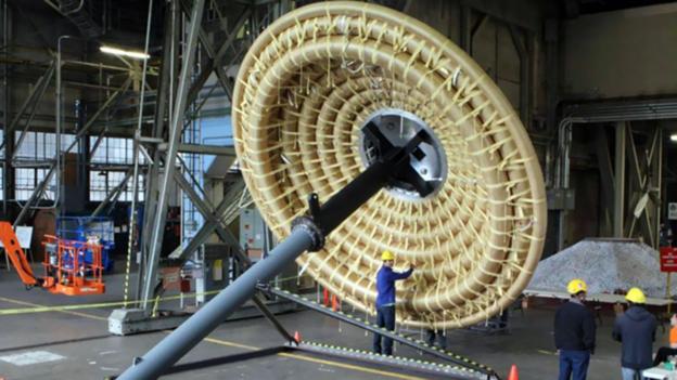
NASA heat shield could enable Mars surface deliveries
Low-Earth Orbit Flight Test of an Inflatable Decelerator (LOFTID), the NASA heat shield’s first test was on November 10, 2022. It launched from the United Launch Alliance (ULA) Atlas V rocket and demonstrated a successful inflatable aeroshell. The Hypersonic Inflatable Aerodynamic Decelerator (HIAD) aeroshell could help large spacecraft to safely descend through the atmosphere of Mars, Venus, and Saturn’s moon, Titan. “Large-diameter aeroshells allow us to deliver critical support hardware, and potentially even crew, to the surface of planets with atmospheres. This capability is crucial for the nation’s ambition of expanding human and robotic exploration across our solar system,” said Trudy Kortes, director of the Technology Demonstrations Missions (TDM) program.
I am not sure what happened to the topic of hyercone or ballutes but they seem to be gone from the great crash...
Nasa is currently working on the Hypersonic Inflatable Aerodynamic Decelerator (HIAD) which is another cone shaped inflateable....following on the heels of a successful flight of the Inflatable Reentry Vehicle Experiment (IRVE)-3
Hypersonic Inflatable Aerodynamic Decelerator
http://www.bbc.com/future/story/2014031 … rs-landing
https://en.wikipedia.org/wiki/Hypercone_(spacecraft)
Offline
Like button can go here
#6 2023-11-23 18:54:55
- SpaceNut
- Administrator
- From: New Hampshire
- Registered: 2004-07-22
- Posts: 30,758
Re: Heat Shield Design Manufacture Application Maintenance
The front runner to the HIAD program comes from these projects.
Structural Analysis and Testing of the Inflatable Re-entry Vehicle Experiment (IRVE)
INFLATABLE AND FOLDABLE AEROTHERMODYNAMICS DECELERATORS AS PART OF AERO SEKUR EDL TECHNOLOGIES
Offline
Like button can go here
#7 2023-11-23 19:05:12
- SpaceNut
- Administrator
- From: New Hampshire
- Registered: 2004-07-22
- Posts: 30,758
Re: Heat Shield Design Manufacture Application Maintenance
The topic Entry, Descent, and Landing Advanced Mars EDL Technologies for Manned and Unmanned Missions
Low-Density Supersonic Decelerator Project (LDSD) NASA’s “flying saucer” prepares for another spin
Landing a flying saucer on Mars
Offline
Like button can go here
#8 2023-11-27 06:57:00
- Mars_B4_Moon
- Member
- Registered: 2006-03-23
- Posts: 9,809
Re: Heat Shield Design Manufacture Application Maintenance
Heat Shield demo passes the test dubbed 'Just flawless'
https://www.spacedaily.com/reports/Heat … s_999.html
Soviet old solutions
https://www.bbc.com/future/article/2021 … space-tech
The cannonball design of the Vostok also made re-entry to the Earth’s atmosphere simpler. Mercury astronauts had to carefully orientate their capsule for the heatshield to protect them. The Vostok, however, was entirely covered in heat-resistant material and was simply weighted at the bottom so it faced in the right direction.
Chinese sample return from the Moon
Design and implementation of the integrated thermal control system for Chang’E−5 lunar module
https://www.sciencedirect.com/science/a … 6522004106
. An integrated and autonomous thermal management system for robotic lunar spacecraft was designed including a single-phase fluid loop, water sublimator and high temperature thermal protection shield. The single-phase fluid loop driven by a miniature pump served as the thermal bus to collect heat. The water sublimator was applied as a supplementary heat sink of panel radiators to dissipate heat load on the lunar surface. The lightweight thermal protection shield was applied to protect the equipment in confined space from high temperature plume of big-powered engine during powered descent and ascending. The combination heat sink of fixed panel radiators and water sublimator was managed to meet different heat dissipation requirements of the Chang’E−5 lunar module.
Lots of TPS tiles missing on S25 today. It’s important to note that SpaceX likely fully expected this to happen. On S28 every tile was tested using a suction cup to verify adhesion. This was not performed on S25 and as a result a large number of tiles along the ring weld lines fell off during flight.
https://twitter.com/CSI_Starbase/status … 9225679047
In other words, it’s not as bad as it looks.
One day perhaps an Unfolding inflatable Shield for Mars transit?
NASA Space Tiles
https://www.youtube.com/watch?v=CchPemGaEmw
2022 article
NASA’s LOFTID: A New Kind of Heat Shield
https://blogs.nasa.gov/jpss-2/2022/11/1 … at-shield/
Offline
Like button can go here
#9 2024-03-15 15:30:38
- tahanson43206
- Moderator
- Registered: 2018-04-27
- Posts: 24,729
Re: Heat Shield Design Manufacture Application Maintenance
The subject of heat shields is front an center in the topics following SpaceX Starship testing ...
I would like to point out Mars_B4_Moon reporting on heat tile loss in the post above #8
The purpose of ** this ** post is to point out there is a technology available today that was NOT available previously... 3D Printing.
GW Johnson is headed to the Carbon Society conference on thermal management in the next few days ...
Let's provide a vigorous discussion of possible 3D printed heat shield for Starship.
There are companies investing in their personnel attending this event.
One of them (or a consortium) might be interested in developing a 3D Printed heat shield for Starship.
The business for the product is going to be huge.
(th)
Offline
Like button can go here
#10 2024-03-15 15:42:16
- tahanson43206
- Moderator
- Registered: 2018-04-27
- Posts: 24,729
Re: Heat Shield Design Manufacture Application Maintenance
Here is a reply from Quora that tries to answer a question about heat shield design using Carbon ...
Mike Miller
Studied Materials Science and EngineeringUpvoted by
Chris King
, BS Aerospace and Aeronautical Engineering & Computer Science, California State Polytechnic University, Pomona… and
Parth Yawale
, B. Tech Aerospace and Aeronautical Engineering, Manipal University (2021)Author has 10.7K answers and 59.4M answer viewsUpdated 2y
Has anyone considered using 3D printed graphene heatshield for starship?That might’ve been considered, but it wouldn’t work for several reasons:
Graphene is pure carbon. It burns just fine when heated in the presence of oxygen.
At large scales (i.e., above 1 centimeter), graphene does not exhibit exceptional strength or properties. It acts like graphite. So, there’s not much reason to deal with the cost of a large graphene structure.
3D printed graphene isn’t a thing for large structures. Some 3D printing efforts have produced resins and gels that blend in graphene or graphene oxide powder, but those don’t offer interesting properties.
If you wanted a carbon-based heat shield then you’d be better off using a carbon-carbon heat shield like some of the shuttle’s panels. During the processing you could easily add oxidation barriers like silicon carbide, not to mention insulation.
(th)
Offline
Like button can go here
#11 2024-03-15 16:11:33
- GW Johnson
- Member
- From: McGregor, Texas USA
- Registered: 2011-12-04
- Posts: 6,222
- Website
Re: Heat Shield Design Manufacture Application Maintenance
Ed Pope at Matech has a porous ceramic composite material that looks like a winner to me, given a thin hard impermeable layer exposed as the surface. It comes in big plates you can more easily tie down, too. It's a re-radiating refractory, good to around 5000 F.
Bear in mind that re-radiating refractories (even Pope's material) cannot serve above about 10 km/s at entry interface. The plasma sheath is opaque to re-radiated IR, just like it is opaque to radio starting at lower speeds. The plasma sheath radiation starts to overwhelm the convective heating from about that same 10 kms on up. You must use ablatives. There is no other proven solution. Lots of concepts, nothing proven.
GW
Last edited by GW Johnson (2024-03-15 16:13:25)
GW Johnson
McGregor, Texas
"There is nothing as expensive as a dead crew, especially one dead from a bad management decision"
Offline
Like button can go here
#12 2024-03-15 17:24:38
- tahanson43206
- Moderator
- Registered: 2018-04-27
- Posts: 24,729
Re: Heat Shield Design Manufacture Application Maintenance
For GW Johnson re #11
Glass tiles were used on the Shuttle. Your post says that "there is no other proven solution".
I'm not sure what to think. Carbon-Carbon was used for the leading edge of the Shuttle surfaces.
Was all that material replaced after each flight?
I was under the impression the glass tiles were able to serve for more than one flight.
Oh! I think I get it.... you're talking about re-entry from Moon or Mars, which is much faster.
Would glass fail if the vehicle is returning from beyond LEO?
(th)
Offline
Like button can go here
#13 2024-03-15 17:27:26
- tahanson43206
- Moderator
- Registered: 2018-04-27
- Posts: 24,729
Re: Heat Shield Design Manufacture Application Maintenance
For GW Johnson ...
Assuming (for the moment) you are right ....
If ablatives must be used, and the ablative tiles must be replaced after each Starship flight, then the answer would be to automate the process so that all tiles that need swapping are replaced using automation while the tanks are being refilled.
(th)
Offline
Like button can go here
#14 2024-03-15 17:38:58
- SpaceNut
- Administrator
- From: New Hampshire
- Registered: 2004-07-22
- Posts: 30,758
Re: Heat Shield Design Manufacture Application Maintenance
There were three different tile types on the shuttle, and they were used in different locations on the shape for the shuttle.
Depending on location some were bolted onto the airframe while as Robert indicated a felt and adhesive was used to keep them adhered to the surface of the ship.
Offline
Like button can go here
#15 2024-03-15 20:01:20
- tahanson43206
- Moderator
- Registered: 2018-04-27
- Posts: 24,729
Re: Heat Shield Design Manufacture Application Maintenance
For SpaceNut re #14
Thank you for the reminder there were three kinds of heat protection on the Shuttle ...
Because this topic is intended, would you be willing to look for a link where those protection types are defined? There may well be a Wikipedia article.
My hope for this topic is that it will become a resource for those who might be wanting to design a heat protection system for a new space vehicle.
We only have one member who can actually speak to the question, but all of us can help by finding resources and posting the links with a bit of text explaining what they are about.
(th)
Offline
Like button can go here
#16 2024-03-16 11:45:50
- GW Johnson
- Member
- From: McGregor, Texas USA
- Registered: 2011-12-04
- Posts: 6,222
- Website
Re: Heat Shield Design Manufacture Application Maintenance
I put a lot of the answers to Tom's questions in an email to Tom.
Be aware that the "glass" he refers to regarding shuttle tile was merely a glassy ceramic top coat applied to a very porous alumino-silicate tile. The "glass" served 2 purposes: (1) to seal the tile against gases flowing right through it, and (2) to apply either a black or white surface coloration.
The more emissive black tiles were used on the windward side, where higher thermal re-radiation was needed to balance the convective heating. They could be poorly-emissive white on the leeward surfaces, where there was much less heating to balance with re-radiation.
The "trick" was running the tile surface hot enough to balance incoming and outgoing energy rates, without exceeding a material surface temperature limitation of about 2000 F. The material undergoes a solid phase change at about 2350 F, after which it shrinks, cracks, and might start to crumble, if you exceed that limit. Quoting meltpoint 3250 F is deceiving; if it embrittles and cracks upon cooldown because it exceeded 2350 F, it is not in any way reusable. You can only do that once.
The high porosity, low density of the ceramic tile bulk confers very low thermal conductivity, essentially cutting off the path for conduction into the interior. That's the ONLY reason these tiles could be glued to an aluminum airframe underneath! Aluminum is junk if it exceeds about 350 F, and RTV adhesive becomes carbon char just above 700 F. A more dense tile (lower porosity) leads to much greater conductive heat flow inward, and a higher backside temperature that is much harder to hang onto.
The extreme case is the much-touted modern super-ceramics that survive temperatures in the 5000-7000 F range. These are very dense, very conductive, and will soak out very nearly isothermal. There is NOTHING with which we can hang onto anything that hot! Until there is a way to do that, such materials are quite useless in any practical sense, and the rest is all marketing hype (spelled "lies").
GW
Last edited by GW Johnson (2024-03-16 11:51:32)
GW Johnson
McGregor, Texas
"There is nothing as expensive as a dead crew, especially one dead from a bad management decision"
Offline
Like button can go here
#17 2024-03-16 17:17:05
- tahanson43206
- Moderator
- Registered: 2018-04-27
- Posts: 24,729
Re: Heat Shield Design Manufacture Application Maintenance
This post is advance notice of a possible quote from Dr. Johnson's email if he grants permission.
It covers much of the material in Post #16 but more besides.
The bottom line appears to be that the design of the heat management system has to be configured for the specific vehicle and mission.
I learned (for example) that Carbon-Carbon used at the leading edges of Shuttle was ablative, but the rate was slow enough so the material could be reused up to 12 times, but eventually had to be replaced.
Until a solution is found to the undisciplined behavior of molecules accelerated from rest to the velocity of an arriving space vessel, it appears we are going to have to put up with the consequences. I've pointed out this problem previously, and this is a good opportunity to repeat it. Molecules in air function as little elastic balls which emit radiation when they are accelerated in a new direction. Since the molecules that encounter an arriving space craft bounce away with a velocity at least equal to that of the vehicle, they collide with nearby molecules, so the entire region participates in the exercise.
The British tried to impose some discipline on the air molecules with their cooling concept, but something a lot more effective than that is needed. The ideal system would capture each molecule, accelerate it to the vehicle velocity and prevent it from jiggling other molecules. To the best of my knowledge (admittedly limited) humans are presently unaware of a way to accomplish this, so the existing heat management systems are all we have to work with.
(th)
Offline
Like button can go here
#18 2024-03-17 10:08:20
- tahanson43206
- Moderator
- Registered: 2018-04-27
- Posts: 24,729
Re: Heat Shield Design Manufacture Application Maintenance
With permission, here is a quote from an email about heat shields...
The shuttle tiles were very porous alumino-silicate ceramic in their bulk. The "glass" wasn't glass as we know it, but a glassy ceramic surface layer to seal the surface and make it non-porous. That was also how they got the white or black color. This alumino-silicate material melts around 3250 F, but has a solid phase change at around 2250 F that causes about 3% shrinkage with embrittlement cracking upon cooldown, which is why tile service was limited to areas only up to 2000 F. The nose-tip and aerosurface leading edges, being at or near stagnation zones, got closer to 3000 F, which is why they were made of carbon-carbon composite, a slow ablative at orbital entry conditions. These would be replaced every 10 flights, plus or minus. This was judged by the incurred erosion accumulated.
At only orbital speeds from low circular orbit, some 8 km/s at entry interface, there is no significant radiation heating from the glowing plasma. There is only the convective heating. The tiles re-radiate from their hot exposed surface the same heat rate as the applied convection. That surface temperature is exactly that which is needed, to produce an amount of re-radiation equal to the applied convection. Their high porosity, low effective density produces the low thermal conductivity to essentially cut off conductive heat flow into the interior, which is why you can glue them to aluminum airframe structure.
The carbon-carbon also re-radiates, an amount equal to the applied convection less the small amount of heat carried away in the ablation gases. Heating at and near stagnation zones is higher, so the equilibrium re-radiation temperature is higher, but this carbon-carbon material ablates rather slowly at these conditions. Its density and thermal conductivity are higher, so it is a lot harder to hang onto the heated part, and you must have insulation behind it to protect adjacent structures from its conducted and re-radiated heat. But, it does ablate, and eventually erodes enough that you must replace it.
The only reason this re-radiation cooling works at all is that at only 8 km/s entry interface speeds, the glowing plasma is still optically transparent to heat (IR). You can see this at optical wavelengths as a sort-of translucent appearance. But, as speed increases at entry interface toward 10 km/s, the glowing plasma gets much brighter and looks optically-opaque. It has also gotten opaque to infrared, and so re-radiation cooling fails. From that point, only ablation will serve. And at only 10 km/s, carbon-carbon is too slow. Which is why silicone polymers are used (since Gemini). These are loaded with microballoons to lower density (and weight), and also to raise ablation rates into the range required for entry. There, I went and told you how Avcoat fundamentally works.
It's just that as the polymer chars into a charcoal-like material, that stuff is quite fragile and easily torn apart by the harsh fluid scrubbing forces, even at vanishing air density. Which is why on Mercury and Gemini, they learned to bond a hex honeycomb structure to the heat shield baseplate, and then "gun" the Avcoat into the hex cells, to create a monolithic heat shield integrally attached to the base plate, in turn integrally attached to the vehicle structure. That serves up to about 11 km/s, which was essentially the entry interface speed for Apollo coming back from the moon. Maybe higher, but probably not 12+ km/s for coming back from Mars, unless you make it a lot thicker. That's the mistake "they" made with the second Orion capsule flight, Artemis 1. They deleted the hex, and lost too much char too fast and too erratically.
You have to deal with the heat flow conducted inward, which on a transient can be "dumped" into a heat sink mass, that being the heat shield and its substrate plate. Depending on the integrated heat absorbed and the mass of the heat shield and substrate plate, the attachment of substrate to vehicle structure may get too hot for aluminum. Every design is different.
That transient effect is what makes heat-sinking your way through entry possible. Steady hypersonic flight in the atmosphere is not a transient, so you cannot heat sink your way through it. Quite often, the thermal management of hypersonic flight is a tougher problem to solve than atmospheric entry. And THAT ugly little truth is why I often say that, unless you have a thermal management plan that is feasible, your "favorite hypersonic airplane design" is fundamentally infeasible, no matter what propulsion you propose. I see a lot of BS about hypersonic flight. It applies to missiles, too.
The plasma sheath opaqueness is why SpaceX's re-radiating ceramic tiles will NOT work for a Starship coming back from Mars! Those will need to be ablative tiles. Which will be fundamentally non-reusable. Although they could easily serve a 7.5 km/s entry at Mars, and then a 12-17 km/s entry at Earth, in something that could be made. Free entry speed depends upon how fast a trajectory you try to fly, but falls in the 12-17 km/s range. I notice nobody is talking about that.
Yeah, I know this crap is complicated. There's no such thing as a "one-size-fits-all" heatshield. And that is a very unpopular truth.
GW
(th)
Offline
Like button can go here
#19 2024-03-18 06:47:01
- tahanson43206
- Moderator
- Registered: 2018-04-27
- Posts: 24,729
Re: Heat Shield Design Manufacture Application Maintenance
This post is about possible use of a ribbon of heat shield material wrapped around the exterior of Starship...
The cylindrical shape of Starship provides an opportunity.
A ribbon of Carbon based ablative material can be wrapped around the entire body of the Starship, so there is no area not protected.
The inability of the Starship to control it's attitude would be less of a problem it the entire body were protected.
The ribbons would be joined together with suitable fasteners, so they could be removed and replaced when they wear out.
I'm thinking here of GW Johnson's observation that Space Shuttle carbon-carbon material was able to survive for up to 12 flights before it became unsafe.
(th)
Offline
Like button can go here
#20 2024-03-21 09:35:51
- tahanson43206
- Moderator
- Registered: 2018-04-27
- Posts: 24,729
Re: Heat Shield Design Manufacture Application Maintenance
GW Johnson reported (by email) that he has seen a picture of the studs welded to the exterior of the Starship to hold tiles.
If anyone can find an image showing the studs, it would be a valuable addition to this topic.
Images of the tiles themselves would be welcome.
The tiles have been coming off, so I would expect that there will be changes made.
The images of the current versions will be valuable for comparison.
(th)
Offline
Like button can go here
#21 2024-03-21 13:06:34
- GW Johnson
- Member
- From: McGregor, Texas USA
- Registered: 2011-12-04
- Posts: 6,222
- Website
Re: Heat Shield Design Manufacture Application Maintenance
See Human Missions, Starship is Go, post 1752. Somebody posted a photo there, of the pins and tiles on Starship. The pins seem to have a split, and maybe a bit of a knobbed end, or maybe not.
My suggestion was to apply RTV silicone to the pin to more securely hold onto the tile. It may not be enough.
As the vehicle tumbles (and I believe I saw both pitch and roll disturbances in the SpaceX video, indicating total loss of attitude control as re-entry began), the tiles at the edge of the heat shield will "randomly" see a strong wind coming at them tangential to the surface, from the unprotected side toward the protected side. The air gets under the edges of the tiles, pressurizes that space, and so pries them up, causing them to come off the pins.
This cascades like opening a zipper, from each band of tiles oriented across the wind direction to the next. It can rapidly strip bare major chunks of airframe that were supposed to be protected.
There is also the issue of ice, which is what the small white flecks departing the vehicle may well have been. If ice forms between the tiles and the metal hull, due to the humid air contacting the cold tank walls under the tiles, then as the vehicle flies into space, this ice will slowly sublime, being quite limited in the amount of heat available for phase change. That's no risk.
Re-entry is quite different, there is very much heat available, and it can get to the ice under the tiles, and cause it to essentially explode into steam! Both the emplacement of the ice under the tiles, and how the heat gets under there to suddenly sublime it, are precisely due to the tiles not being bonded down, but instead held down by the pins.
If my suggestion to glue the pins to the pin-holes in the tiles is not strong enough, then they will have to bond down the tiles to the hull. That's an answer they really didn't want, or they would have done it that way in the first place! But if ice under the tiles is exploding into steam, those steam explosion forces may just be too strong.
Bonding the tiles down would stop the infiltration of ice under the tiles, and would be a stronger retention force than the pins can be (it's a contact area thing).
As for the loss of attitude control, the answer is simple: strong attitude thrusters. That has been known since Mercury in 1961. It works.
GW
Last edited by GW Johnson (2024-03-21 13:13:22)
GW Johnson
McGregor, Texas
"There is nothing as expensive as a dead crew, especially one dead from a bad management decision"
Offline
Like button can go here
#22 2024-03-21 14:33:00
- Void
- Member
- Registered: 2011-12-29
- Posts: 9,513
Re: Heat Shield Design Manufacture Application Maintenance
Normally I would not post after expert materials Dr. Johnson, for fear of being stupid. So, I will be careful.
I feel you have illuminated some things for me, so thanks.
Starship is different than the Shuttle, as tank flexing and thermal shrinking and expansion is also involved, where the propellants are proximate. So, that looks pretty tough for them to solve.
It may be that in trips to Mars or from Mars to Earth, any ice over time would sublimate without as much problem with the heating of the ices, if you were careful.
I am thinking that Stokes Space, if it works may be a method to consider. But I don't know if it could be sized up to Starship size and work successfully. You have already indicated that such a heat shield will not work for a more stressful situation than reentry from LEO.
This is just to indicate where I am at with my thinking after your post.
Done
Last edited by Void (2024-03-21 14:36:04)
Is it possible that the root of political science claims is to produce white collar jobs for people who paid for an education and do not want a real job?
Offline
Like button can go here
#23 2024-03-21 17:33:03
- SpaceNut
- Administrator
- From: New Hampshire
- Registered: 2004-07-22
- Posts: 30,758
Re: Heat Shield Design Manufacture Application Maintenance
We know that the fuels make ice so build up under tiles seem plausible..
Offline
Like button can go here
#24 2024-03-21 21:03:58
- Void
- Member
- Registered: 2011-12-29
- Posts: 9,513
Re: Heat Shield Design Manufacture Application Maintenance
Perhaps this will be worth looking at: https://www.youtube.com/watch?v=Srt9kzVQBNI
Quote:
101: SpaceX's Starship HEAT tiles
Ellie in Space
The thing to note is that at some point the back side of a full heat tile is shown by the owner who recovered it.
I has a "Y" architecture which, I think could touch the "Felt" that lines the stainless steel. So, it may be that some ventilation may exist for ice that accumulates. Ideally the ice could evaporate to vent to the joins between hexagonal tiles, but of course the amount of ice may matter. And then the heating rate may matter upon reentry. So, we would not want pressure buildups, maybe there is a way to minimize that kind of problem.
So, the tiles can perhaps handle some of the heat, and the "Felt" give a bit more protection and then the Stainless Steel is rated to a fairly high temperature. And the tiles might be sending reduced thermal conduction to the felt and metal tank as only the "Y" may be in direct contact.
Just guesses though, please don't get a rope for me just yet.
Done
Last edited by Void (2024-03-21 21:12:18)
Is it possible that the root of political science claims is to produce white collar jobs for people who paid for an education and do not want a real job?
Offline
Like button can go here
#25 2024-03-21 22:55:01
- kbd512
- Administrator
- Registered: 2015-01-02
- Posts: 8,533
Re: Heat Shield Design Manufacture Application Maintenance
I probably have a different idea related to how to solve this, but it's similar to what NASA did for their TUFROC high temperature tiles on the X-37. Rather than adhesives and felts, they opted to use mechanical fasteners. They were using bolts affixed to the shaft / shank of the TUFROC parts because they were primarily used in the leading edges. This allowed for a little bit of play between tiles.
For example:
Imagine you have a steel ring partially embedded into each hexagonal PICA tiles. There's a flange sticking out the end facing the propellant tank. Around that flange, you have an adjustable snap-ring and a sheet steel slot weldment on the exterior of the tank. We could forego weldments for each tile and use rails as well. This slot allows you to wiggle the tile just a bit for a small uniform gap between each tile, perhaps the thickness of a credit card. When your tile is shimmed into place, you rotate the snap ring and it locks the tile in place. Said snap ring will have a large bearing surface area so that each tile is held in place somewhat near the its edges.
The idea behind this is to maximize attachment strength without large forces applied to the tile which might crack it. The net effect should be an improvement to your ability to "hold onto" the tile, and each snap ring weldment on the tank acts as a type of "spring", so as to allow each tile just a little freedom of movement as the propellant tank flexes from thermal cycling or aero loads applied to it. This reduces the possibility of cracking at the edges of each tile, or losing them entirely. I don't know what the optimal sizes and edge geometries are, but there must be a "right size", dependent upon the tank size or part size being protected.
Offline
Like button can go here