New Mars Forums
You are not logged in.
- Topics: Active | Unanswered
Announcement
#401 Re: Science, Technology, and Astronomy » Amateur solid-fueled rockets to *orbital* space? » 2017-09-16 07:35:55
Lessee, a 5 sec burn at a nominal 0.3 in/sec for AP-composites yields a web burned of 1.5 inches, about 50% of the radius of a 6-inch motor. That's definitely in the ballpark for the thrust-time curves you posted. I cannot pin down a pressure from this, as burn rates are tailorable from 0.2 to 1+ in/sec at 1000, and pressure exponents are typically quite low (near 0.3).
Reducing motor pressure from 1000 psia to around 500 psia, with a 14.7 psia backpressure, reduces pressure ratio from 60-ish to 30-ish, which reduces CF from near 1.5 to nearer 1.4. That reduces c* from just over 5000 ft/sec to around 4800-4900 ft/sec, which is just about what I computed from the tabular thrust and impulse data from their propellant weight.
I would hazard the guess their average chamber pressure is nearer 400-500 psia, which brings down Isp into the range they quote.
Based on this estimate of burn rate for APCP motors, we can get a longer burn rate by doubling the diameter. Such longer burn motors though won't be "off-the-shelf" for Cesaroni.
Could amateurs make their own APCP of this size? I did see on the net discussion of amateurs making their own APCP though not in the size range we require. You mentioned the dangers of making AN propellant, such as vacuum-curing. Is APCP simpler and/or safer than this?
The SS-520-4 is an example of a solid motor orbital rocket that had stages with short burn times in the 20 to 30 second range for the separate stages:
Experimental Launch of World’s Smallest Orbital Space Rocket ends in Failure.
January 14, 2017
http://spaceflight101.com/ss-520-4-rock … l-mission/
The first test flight wasn't successful for the SS-520-4 but this is believed to be due to an easily correctable electrical flaw in the first stage.
Bob Clark
#402 Re: Science, Technology, and Astronomy » Amateur solid-fueled rockets to *orbital* space? » 2017-09-15 10:34:50
I've gotten feedback about the proposed solid-rocket cube-sat launcher discussed in post #40. The main criticism is the high acceleration and therefore high drag associated with these stages which only have a burn time of about 5 seconds. So to remove this objection, could we lengthen the burn time?
If we kept the same propellant amount by shortening the length of the Pro150 segments by a factor of 4 but increasing the radius by a factor of 2, so the volume is the same, this would mean the internal burn surface area would decrease by a factor of 2.
This should mean the propellant burn rate should decrease by a factor of 2, right? Then IF the Isp remained the same, the thrust would be cut in half. At the same time, the burn time is determined by the thickness of the loaded propellant, so if this is doubled the burn time should be doubled, correct?
Would this be a way to reduce the thrust, thus reducing the T/W ratio, and increase the burn time, while keeping the Isp the same?
Bob Clark
#403 Re: Unmanned probes » Mars InSight lander » 2017-09-05 08:19:09
Preparations for Deployment of InSight Lander to Mars are Ramping Up!
InSight Lander for its scheduled launch in 2018.
Once deployed to Mars, the lander will reveal things about Mars’ interior geology and composition, shedding new light on the history of the Red Planet’s formation and evolution.
Mars Insight scheduled to land near the equator already will be a great geology mission but the recent discovery of large water deposits near the equator on Mars raises the possibility it could also be a great astrobiology mission:
Water ice found near Mars’s equator could entice colonists and life-seekers.
Find also poses climate puzzle.
SCIENCEMAG.ORG
http://www.sciencemag.org/news/2017/08/ … fe-seekers
The full research article is available free, full-text online:
Equatorial locations of water on Mars: Improved resolution maps based on Mars Odyssey Neutron Spectrometer data.
Icarus, Volume 299, 1 January 2018, Pages 148-160.
Jack T.Wilson, Vincent R.Eke, Richard J.Massey, Richard C.Elphic, William C.Feldman, Sylvestre Maurice, Luís F.A.Teodoro
http://www.sciencedirect.com/science/ar … 3516306029
Mars Insight is scheduled to land in Elysium Planitia at 4°N 136°E:
Mars Insight.
https://en.wikipedia.org/wiki/InSight#S … ic_payload
Here is a map from the Icarus paper showing the regions of high water(ice) content:

Notice in the second panel in the image there is a region of high water content indicated in blue near the Mars Insight landing site. However, for Mars landers you can't get the landing position exactly right and there is unfortunately a larger area above and to the right of very low water content indicated in red near the landing site. The question is could they stick the landing near the high water region?
One of the Mars Insight instruments might be ideal for detecting the near surface water since it will include a subsurface borer able to drill down to 5 meters:

But what instruments could be used to distinguish liquid water from ice water?
In view of the possibility of liquid water existing near surface, I would also like to see a true microscope put on the lander. Of all the landers sent to Mars none included a true optical microscope. The best optical resolution of the imagers sent to Mars were no better than that of a geologist's hand lens.
Bob Clark
#404 Re: Meta New Mars » Introducing myself » 2017-09-02 10:30:45
Welcome to the forum! The Mars Society is holding its convention in California starting Thursday. Are you planning on attending?
THE 20TH ANNUAL INTERNATIONAL MARS SOCIETY CONVENTION.
University of California, Irvine
A311 Student Center
Irvine, CA 92697
September 7 - 10, 2017
http://www.marssociety.org/conventions/2017/
Bob Clark
#405 Re: Science, Technology, and Astronomy » Amateur solid-fueled rockets to *orbital* space? » 2017-08-26 11:23:54
Hi Bob:
It was hard to tell for sure, but it looks like that outfit makes 1 single propellant grain, and sells various cases that hold anywhere from 1 to 6 of them. I could not identify what that grain design actually is, but clearly there is a port down the middle.
Obviously, they are not having the resonance instabilities that going from a 4-segment to a 5-segment SRB design encountered, but that's a function of absolute size, as well as shape proportions, and what species are in the 2-phase flow mix.
That being the case, perhaps they don't offer a 7 grain stack because the bore port would come too close to choking, which usually leads to sudden motor explosion. The port is pretty big to pass the massflow from 6 grains, which means web fraction and volumetric loading are fairly low, regardless of the design details.
GW
You mean the "grain" simply means the weight of propellant?
Bob Clark
#406 Re: Science, Technology, and Astronomy » Amateur solid-fueled rockets to *orbital* space? » 2017-08-24 19:51:40
GW, looking at some prices for these solid rockets, I saw the price depended on the "grain" size, with the grain listed from 1 to 6.
What is the "grain" size, and why do the higher grains cost more, perhaps by two to three times more for 6 grain over 1 grain?
See here:
http://www.the-motorman.net/6452.html
Bob Clark
#407 Re: Science, Technology, and Astronomy » Amateur solid-fueled rockets to *orbital* space? » 2017-08-22 19:28:28
Discussion of low cost orbital rockets for cubesats and smallsats that are within the capabilities of most university undergraduate labs:
Orbital rockets are now easy, page 2: solid-rockets for cube-sats.
http://exoscientist.blogspot.com/2017/0 … age-2.html
Feasibility comments encouraged.
Bob Clark
#408 Re: Science, Technology, and Astronomy » Amateur solid-fueled rockets to *orbital* space? » 2017-08-20 18:54:31
...
So take the cost of the third stage, derived from the Cesaroni Pro1050, as $3,000, and the second stage 4 times larger as $12,000, and the first stage larger by an additional factor of 4 as $48,000. So $63,000 for a small sat launcher with a 7 kg payload to orbit.Bob Clark
To save, costs I'm envisioning making the components as much "off-the-shelf" as possible. But among its standard products Cesaroni offers the Pro150 as the largest motor. So to get the larger second and first stages, I would have to combine multiple copies of this motor.
I could cluster them in parallel, but for the first stage that would be 16 of them, and you would have the problem of simultaneous ignition with that many motors.
So what I'm envisioning is take 4 copies of the Pro150 stacked vertically one on top of the other for the second stage, then cluster 4 of these second stage motors in parallel for the first stage.
The question I have about the vertical stacking though is how much the thrust scales in this case. If for the solid motors the propellant burned from the bottom upwards, then the thrust would be the same as for a single motor, you would just get 4 times longer burn time.
But that's not how solid motors work. Actually, they have a hollow region in the center so the propellant burns from the inside surface, proceeding outwards.
In this case, this would seem to mean you have a greater amount of propellant being burned per second because of the larger vertical area with the stacked segments. In fact the thrust should scale linearly with the number of segments. Is this correct?
BTW, the reason why I don't just also stack the first stage vertically, is because of the thinness of the rocket that would result. The Pro150 is about 3 feet long and 1/2 foot wide. If you stacked vertically 16 for the first stage, 4 for the second, and 1 for the third, that would be a rocket 63 feet high but only 1/2 foot wide, for a ratio of length to width of over 120 to 1.
This ratio of length to width is called the "fineness ratio". Rocket engineers don't like for it to be higher than about 20 to 1 because of the severe bending loads that would result. The upgraded version of the Falcon 9 has been noted for its long, skinny profile, and has a fineness ratio of about 20 to 1. The Scout solid rocket had a fineness ratio of about 24 to 1. Solid rockets can support a higher fineness ratio because their thicker walls can withstand higher loads. Still, 120 to 1 would very likely be too high.
So to avoid this I decided to form the first stage by clustering in parallel 4 copies of the second stage.
Bob Clark
#409 Re: Science, Technology, and Astronomy » Amateur solid-fueled rockets to *orbital* space? » 2017-08-20 02:59:03
...
Scout used "off the shelf" motors from the solid propellant companies (in those days there were many). None of these had any "trick" nozzles, just plain ablative convergent-divergent designs. It had small fins to enhance aerostability while the first stage was burning. The control system fired hydrogen peroxide thrusters to correct an attitude angle if it drifted out of an acceptable deadband. Very simple, but worked like a charm.
Memory fails, but I think I remember we were putting 200-pound-class payloads into geosynch transfer trajectories in 1974.
GW
I'll need some type of attitude control for the upper stages operating in little atmosphere, as fins would be ineffective. How did the hydrogen peroxide thrusters work?
Bob Clark
#410 Re: Life on Mars » Where Should we Send our Rovers to Mars to Look for Early Life? » 2017-08-19 09:42:45
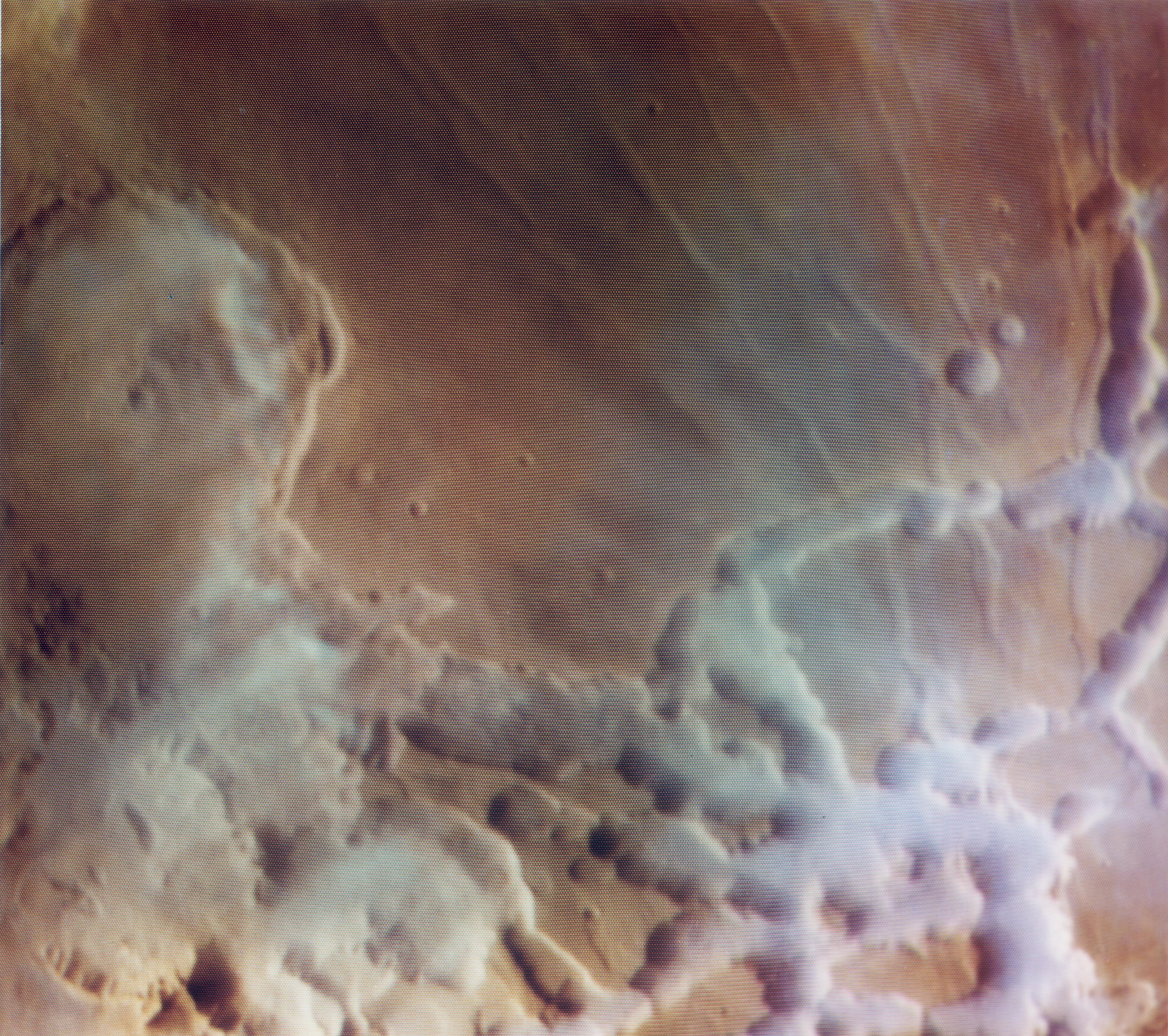
With the recent reports of liquid water being possible on Mars as brines, I like the Noctis Labyrinthus region because of the frequent low lying fogs:
http://www.ridingwithrobots.org/wp-cont … A03213.jpg
Bob Clark
Water ice found near Mars’s equator could entice colonists and life-seekers.
Find also poses climate puzzle.
SCIENCEMAG.ORG
http://www.sciencemag.org/news/2017/08/ … fe-seekers
Very interesting finding. Daytime surface temperatures near the equator can be well above freezing. That raises the possibility of liquid water near surface at these sites.
Could Curiosity or Opportunity visit one of these sites?
One of these sites might be a good location for the Mars 2020 rover.
Noctis Labyrinthus is my favorite site for the Mars 2020 rover because of its frequently low lying fogs and clouds. This may be indicative of the near surface water ice now known to exist at equatorial sites such as Noctis.


Bob Clark
#411 Re: Science, Technology, and Astronomy » Amateur solid-fueled rockets to *orbital* space? » 2017-08-18 01:47:12
http://nasawatch.com/archives/2017/08/g … -on-i.html
GAO estimated that DOD could sell three Peacekeeper motors—the number required for one launch, or, a "motor set"—at a breakeven price of about $8.36 million and two Minuteman II motors for about $3.96 million, as shown below. Other methods for determining motor prices, such as fair market value as described in the Federal Accounting Standards Advisory Board Handbook, resulted in stakeholder estimates ranging from $1.3 million per motor set to $11.2 million for a first stage Peacekeeper motor.
Article doesn't say how much these motors repurposed as orbital launchers could loft to orbit. Anyone know that?
Bob Clark
#412 Re: Science, Technology, and Astronomy » Amateur solid-fueled rockets to *orbital* space? » 2017-08-17 02:42:21
I've looked into this before...can't remember any real details but I think you could get one or two people off the surface of Mars with a few tonnes (maybe 5-8 tonnes) of fuel/propellant. Think it was 3 tonnes for the Moon...but technology moves on.
I thought of using small solid motors to do a Mars sample return mission. It would seem to cost a small fraction of NASA's $10 billion estimate for such a mission.
But the calculation in that last post was to suggest any university would have the capability of conducting their own smallsat launch to LEO.
Bob Clark
#413 Re: Science, Technology, and Astronomy » Amateur solid-fueled rockets to *orbital* space? » 2017-08-16 19:11:37
Lessee, a 5 sec burn at a nominal 0.3 in/sec for AP-composites yields a web burned of 1.5 inches, about 50% of the radius of a 6-inch motor. That's definitely in the ballpark for the thrust-time curves you posted. I cannot pin down a pressure from this, as burn rates are tailorable from 0.2 to 1+ in/sec at 1000, and pressure exponents are typically quite low (near 0.3).
Reducing motor pressure from 1000 psia to around 500 psia, with a 14.7 psia backpressure, reduces pressure ratio from 60-ish to 30-ish, which reduces CF from near 1.5 to nearer 1.4. That reduces c* from just over 5000 ft/sec to around 4800-4900 ft/sec, which is just about what I computed from the tabular thrust and impulse data from their propellant weight.
I would hazard the guess their average chamber pressure is nearer 400-500 psia, which brings down Isp into the range they quote. Most of the military hardware I worked on had chamber pressures above 1500 psia, and we typically got the higher Isp values.
...
GW
I found this commercial solid motor with a similar sea level Isp as the Cesaroni solid rocket motors Pro150 I mentioned earlier:
Star 37.
Thiokol solid rocket engine. Total impulse 161,512 kgf-sec. Motor propellant mass fraction 0.899. First flight 1963. Solid propellant rocket stage. Burner II was a launch vehicle upper stage developed by Boeing for the Air Force Space Systems Division. It was the first solid-fuel upper stage with full control and guidance capability developed for general space applications.
AKA: Burner 2;TE-M-364-1. Status: First flight 1963. Number: 180 . Thrust: 43.50 kN (9,779 lbf). Gross mass: 621 kg (1,369 lb). Unfuelled mass: 63 kg (138 lb). Specific impulse: 260 s. Specific impulse sea level: 220 s. Burn time: 42 s. Height: 0.84 m (2.75 ft). Diameter: 0.66 m (2.16 ft).
Thrust (sl): 33.600 kN (7,554 lbf). Thrust (sl): 3,428 kgf.
http://www.astronautix.com/s/star37.html
So we might estimate the vacuum Isp of the Cesaroni to be in the Star 37's range of 260 s.
Using this as a vacuum Isp of a first stage and a 285 s vacuum Isp of second and third stage I get a three-stage solid rocket able to reach orbit, with not even particular high mass ratios of 5 to 1 for the stages:

With a payload of 7 kg:

And this with standard nozzles, no altitude compensation required.
The Cesaroni Pro150 retails for about $3,000 and in general the Cesaroni solids cost in the range of $100 per kg of the motor mass:
Cesaroni O8000 White Thunder Rocket Motor.
$3,099.95
Product Information
Specification
Brandname: Pro150 40960O8000-P Manufacturer: Cesaroni Technology
Man. Designation: 40960O8000-P CAR Designation: 40960 O8000-P
Test Date: 4/10/2008
Single-Use/Reload/Hybrid: Reloadable Motor Dimensions mm: 161.00 x 957.00 mm (6.34 x 37.68 in)
Loaded Weight: 32672.00 g (1143.52 oz) Total Impulse: 40960.00 Ns (9216.00 lb/s)
Propellant Weight: 18610.00 g (651.35 oz) Maximum Thrust: 8605.10 N (1936.15 lb)
Burnout Weight: 13478.00 g (471.73 oz) Avg Thrust: 8034.50 N (1807.76 lb)
Delays Tested: Plugged ISP: 224.40 s
Samples per second: 1000 Burntime: 5.12 s
https://www.csrocketry.com/rocket-motor … motor.html
So take the cost of the third stage, derived from the Cesaroni Pro1050, as $3,000, and the second stage 4 times larger as $12,000, and the first stage larger by an additional factor of 4 as $48,000. So $63,000 for a small sat launcher with a 7 kg payload to orbit.
Bob Clark
#414 Re: Not So Free Chat » Are current Moon plans trying to copy 1950s movies? » 2017-08-10 18:56:54
Full film Project Moonbase available on the net:
Project Moonbase.
http://www.dailymotion.com/video/x21jtid
Bob Clark
#415 Re: Human missions » Apollo 11 REDUX » 2017-06-26 10:44:08
https://image.slidesharecdn.com/vonbrau … 1225347351
Apollo LM vs Soviet LK
http://astronautix.com/nails/l/lemvslk.jpg
Soviet LK:
Height: 5.20 m
Diameter: 2.25 m
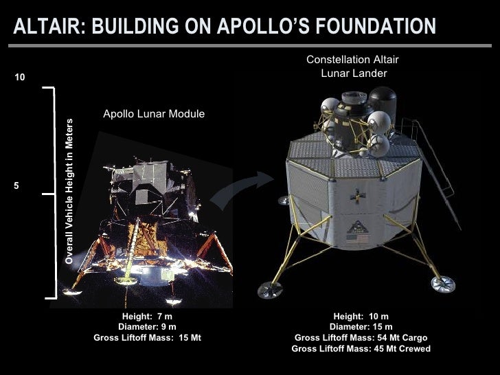
Gross Liftoff Mass: 5,560 kg (5.56 Mt)I said we could launch both crew Dragon with a service module instead of trunk, and a new Lunar Module based on the Soviet LK but designed to carry all 4 astronauts, no science instruments at all, and a modern docking hatch to mate with Dragon. This could be launched on a single SLS. In fact, we could use SLS block 1, however it would require an additional stage. The Interim Upper Stage (IUS) is a Delta IV upper stage, we could use that for TLI. The additional stage would be used for LOI (Lunar Orbit Insertion) and to de-orbit the new LM. The Dragon service module would only be used for TEI (Trans-Earth Injection).
This would be a crew taxi to deliver crew to the Lunar surface. A Mars Direct habitat would be pre-landed, used as a permanent Moon base, launched by SLS block 2B. The Mars Direct habitat would have long-duration life support, science instruments, and a rover.
Key statistic: crew variant of Altair = 45 metric tonnes, LK = 5.56 metric tonnes
As described on the Astronautix.com page, the Soviet LK did not do the full landing on its own. It required the Soviet Block D stage to do most of the propulsion towards the lunar surface, bringing the LK to within 5 km and 100 m/s of the landing. The rest of the landing was done by the LK, as well as doing the take-off.
This type of landing used what's called a "crasher stage" since the Block D would crash into the lunar surface. I'm not a fan of this type of landing, though it's probably just a visceral reaction with this stage crashing and exploding on the lunar surface, even though kilometers away from the lander.
In any case the mass of the LK stage was comparable to the Apollo's ascent stage only, and the full lander was not at a saving in mass to the Apollo full lander.
About the Block D stage:
Block D space tug.
http://www.russianspaceweb.com/n1_d.html
For a replacement for this Block D stage, I like the storable propellant version of the Ariane 5 upper stage:
Ariane 5-2
N2O4/MMH propellant rocket stage. Storable propellant, restartable upper stage for use with Ariane 5. Chamber pressure 10 bar; expansion ratio 83.0; propellant mix ratio 2.05. Empty mass without VEB payload fairing support ring and avionics is 1200 kg.
AKA: L-9. Status: Active. Thrust: 27.40 kN (6,160 lbf). Gross mass: 12,500 kg (27,500 lb). Unfuelled mass: 2,700 kg (5,900 lb). Specific impulse: 324 s. Burn time: 1,100 s. Height: 3.36 m (11.02 ft). Diameter: 3.96 m (12.99 ft). Span: 5.46 m (17.91 ft).
Cost $ : 6.000 million.
http://www.astronautix.com/a/ariane5-2.html
Note that it's actual dry mass without the extra equipment used for its Ariane 5 function would only be 1,200 kg. Given also its high Isp, it could serve as a full stage descent stage, i.e., no separate crash landing for the stage.
Also, nice is its low cost.
Bob Clark
#416 Re: Human missions » Apollo 11 REDUX » 2017-06-25 05:47:31
Still wanting Space x to design a modified lunar lander followed by a mars capable MAV as well...
Can the Dragon V2 land on the moon
Descending and ascending the moon is much easier than on Mars. The Moon is just 17% of earth's gravity while Mars is 38%. The Apollo LM did not need any fancy inflatable re-entry vehicle to land on the moon. Rocket thrusters will suffice.
The Dragon-2 has enough power and fuel to land and ascend back to lunar orbit. The Dragon's SuperDraco has higher performance than the Apollo Lunar Module. Apollo LM descent engines has 10,000 lbf thrust, and 3,500 lbf thrust for ascent (the lander part is left behind). The Dragon's SuperDraco has 16,000 lbf thrust. The Dragon also uses computers to control throttle and land (much more fuel efficient). Hence, the Dragon-2 has enough power and fuel to land and ascend back to lunar orbit even if it carries all it's parts during ascent. However, it may need to cut crew from 7 to 3 to loose more weight for fuel.
The Dragon V2 has enough thrust to takeoff and land on the Moon but not nearly enough delta-v. I've seen the delta-v estimates it's capable of in the range of 400-600 m/s. But it takes ca. 1,850 m/s to takeoff or land on the Moon from lunar orbit.
Edit: proposals I've seen to make the Dragon, either cargo or manned version, a lunar lander involve giving it greater propellant load by adding tanks to the trunk section.
Bob Clark
#417 Re: Science, Technology, and Astronomy » Amateur solid-fueled rockets to *orbital* space? » 2017-06-24 07:31:53
Getting good thrust coefficient CF at low Pc in vacuum is why the vacuum Isp data in my old Pratt & Whitney handbook are for Pc = 100 psia, while the sea level data are for 1000 psia. Thrusters in vacuum are usually quite low chamber pressure, so that the hardware is thinner and lighter.
Same could be true of upper stage engines, but that choice depends more on where that engine design came from: Spacex's second stage Merlin is just the first stage Merlin fitted with a much longer nozzle. They both use the same chamber design.
...
GW
Do you know of examples of those low chamber pressure solid thrusters at Pc = 100 psia? For my upper stage of the all-solid launcher, I want to use one of the size of the Cesaroni motor used on the Up Aerospace suborbital rocket I mentioned in post #13 with a 412 pound fueled weight and 0.8 propellant fraction. This puts is it at about 80 pound empty weight and 320 pound propellant weight. If I got the chamber pressure smaller by a factor of 10, then I could reduce that empty weight to only 8 pounds, and the payload would increase by 72 pounds.
But this means I want to keep the same propellant weight, and use the same size case but only thinner wall thickness by a factor of 10. But I don't know if this is possible for a solid-fueled motor. For a liquid I could just reduce the propellant burn rate to reduce the chamber pressure, i.e., less propellant burn at any time, less pressurized gases produced at any time, therefore lower chamber pressure.
But decreasing the chamber pressure is not so easy to do with a solid. It won't work to just increase the case volume because that eliminates the advantage you wanted to get of having a smaller empty, i.e., case weight. You can't reduce the propellant amount either to get a larger volume for the central open section because you want the same size stage.
Is there some method to get the same amount of propellant to just burn at a slower rate? Another possible way it could work would be by having the propellant compressed to an extreme degree to only 1/10th it's usually volume. Don't know if that is technically feasible.
Bob Clark
#418 Re: Science, Technology, and Astronomy » Amateur solid-fueled rockets to *orbital* space? » 2017-06-23 10:08:39
Thanks for that. Another interesting fact I discovered using the RPA engine analysis program is that you can get high vacuum Isp by using high area ratio even with low chamber pressure. For instance, according to the program, I could let the chamber pressure be only 200 psi instead of 2,000 psi and get a 325 s Isp with a 750 to 1 area ratio.
This low pressure will reduce the thrust. But for an upper stage, where the high Isp is most important, thrust isn't as important. In fact, for upper stages the thrust is often only half the stage weight.
But if the chamber pressure only had to be 1/10th as high, you could reduce the empty weight also by a factor of 10. This would be important for an upper stage to maximize payload.
But I need to know what thrust you could get at this low a chamber pressure. Suppose you used a very high area ratio, say by an aerospike, of 750 to 1. But let the chamber pressure be only 200 psi. What would be the Isp and thrust then?
Bob Clark
#419 Re: Science, Technology, and Astronomy » Amateur solid-fueled rockets to *orbital* space? » 2017-06-19 10:32:25
Speaking of SSTO's, there are some solid stage motors with high mass ratio, in the range of 20 to 1. If this was kerolox or hydrolox with their high maximum vacuum Isp's this would be enough for a SSTO. Unfortunately, for solids their vacuum Isp's are typically only in the range of 285 s.
But I was surprised running the engine simulation program RPA, http://propulsion-analysis.com/index.htm, that the APCP solids could get vacuum Isp's in the range of 325 s and above by using nozzles with extremely high area ratios, in the range of hundreds to 1. Then running the launch performance calculator, http://silverbirdastronautics.com/LVperform.html, I found they could be SSTO.
Here's one solid motor with the high mass ratio:
Star 48
Thiokol solid rocket engine. Used in Delta 3900; Conestoga; PAM-S; PAM-D. Total flown included in total for Star-48-8. Total impulse 575,682 kgf-sec. Motor propellant mass fraction 0.946. First flight 1982.
AKA: PAM-D;PAM-S;TE-M-711-3. Status: Out of Production. Number: 125 . Thrust: 67.20 kN (15,107 lbf). Gross mass: 2,114 kg (4,660 lb). Unfuelled mass: 114 kg (251 lb). Specific impulse: 287 s. Burn time: 88 s. Height: 2.04 m (6.69 ft). Diameter: 1.24 m (4.06 ft).
Chamber Pressure: 40.00 bar. Area Ratio: 49.
http://www.astronautix.com/s/star48.html
Here's how the input screen looks on the launch performance estimator for this motor:

Note there some quirks of this program you need to be aware of if you use it. First, always use the vacuum values for the Isp's and thrust numbers, since the program already takes into account the diminution at sea level. Second, always set the "Restartable Upper Stage" option to "No", rather than the default "Yes", otherwise the payload will be reduced. This is true even for a supposed SSTO.
Third, always set the launch inclination to match the launch site latitude, otherwise the payload will be reduced. This is related to the fact that changing the orbital plane involves a delta-v cost. So for the Cape Canaveral launch site, the launch inclination should be set to 28.5 degrees.
Now, here's the result:

i.e., 0 payload is the estimation.
Now, for the case where the vacuum Isp can be raised to 325 s by using the aerospike or other altitude compensation methods the results are then:

i.e., 33 kg is the payload estimation.
Bob Clark
#420 Re: Science, Technology, and Astronomy » Amateur solid-fueled rockets to *orbital* space? » 2017-06-19 08:40:00
Thanks for the info. The new start-up Arca Aerospace will test this year for the very first time, 50 years after the aerospike was developed, the high altitude performance of an aerospike on their liquid-fueled demonstrator for their planned SSTO:
Flight of the Aerospike: Episode 1.
https://www.youtube.com/watch?v=L1hnImvI2gw
Bob Clark
#421 Re: Science, Technology, and Astronomy » Amateur solid-fueled rockets to *orbital* space? » 2017-06-18 10:39:07
Hi Bob:
...
The thing about vacuum expansion is that the larger you make your expansion area ratio, the higher the Isp performance you get. But such high numbers, while quite real, are often deceptive: there are usually physical real-world limitations on how big you can make your area ratio.
One is the diameter(s) of your nozzle exit(s) exceeding your stage diameter - that simply won't work in any practical vehicle design. Another is the length of such an extremized expansion bell - there is usually no room for super-long nozzles in practical designs, and even if there were, the surrounding adapter shroud connecting the stages gets to be an excessive inert weight.
The vacuum expansion data reported in my ancient Pratt & Whitney handbook were limited to Ae/At = 40 for exactly those same reasons. It is possible in some designs to go larger, but not a whole lot larger. Every design is unique in that respect. The handbook writers used that ratio as a "typical" figure for "representative" data. I see in the much more modern AIAA handbook that they pretty well report vacuum Isp data to the same expansion convention.
The other disparity between handbook Isp data and real-world performance is that in most of the handbooks, the reported vacuum expansion Isp data are for low chamber pressures like in thrusters, down near 100 psia. The sea level data are for a nominal 1000 psia chamber pressure; most modern engines run higher than that, some a lot higher.
...
What do you calculate the Isp would be for a 1,000 psi and 2,000 psi engine with an area ratio of, say, 500 to 1? As you say that would make a regular bell nozzle impractically large, well outside the motor's diameter. But with an aerospike it would stay inside the motors diameter. Surprisingly, after knowing about the aerospike for over 50 years there still have been no high altitude tests of the aerospike where the ambient pressure would be near vacuum. The only flight tests have only been at about 30,000 ft. where the pressure is still 1/3 sea level.
BTW, what do you use as the solid motors throat area when it is not circular but cross-shaped? Also it would seem to me the throat area should change as the solid fuel burns away.
Bob Clark
#422 Re: Science, Technology, and Astronomy » Amateur solid-fueled rockets to *orbital* space? » 2017-06-15 06:45:31
GW, I assume you have some engine performance programs available such as RPA, http://propulsion-analysis.com/index.htm. I was surprised when I tried it that for an extra large, vacuum optimized nozzle, expansion ratio of several hundred, that you can get the vacuum Isp to be in the 325 s range. This would result in a significant increase in payload over the 285 s Isp common with APCP solid rockets.
Another reason why I am a big proponent of altitude compensation methods such as the aerospike.
Bob Clark
#423 Re: Science, Technology, and Astronomy » Amateur solid-fueled rockets to *orbital* space? » 2017-06-15 06:25:40
Why not use a LOX-rubber hybrid? Solid propellants sound downright dangerous. The sort of hobby that could end up depriving a man of his arms.
Some amateur groups are working on hybrid engines. However, they are not as safe as portrayed, as the accident at Scaled Composites shows. Also they are not as well understood as solids and liquids, as the 10 year development cycle to get the hybrid engine on SpaceShipTwo to work properly shows.
Bob Clark
#424 Re: Science, Technology, and Astronomy » Amateur solid-fueled rockets to *orbital* space? » 2017-06-13 18:39:17
GW, I found this after a web search:
CTI rocket motor successfully powers the launch carrying the ashes of astronaut and James Doohan - April 30, 2007.
On April 28th, a Spaceloft™XL rocket successfully completed a round-trip space flight launched from Spaceport America. This rocket was developed by UP Aerospace Inc. of Hartford, Conn. The rocket carried a wide variety of experiments and payloads, which included the cremated remains of Star Trek's "Scotty", James Doohan and NASA astronaut and pioneer Gordon Cooper. In addition, the cremated remains of more than 200 people from all walks of life were onboard. Also flown into space on the SL-2 Mission were dozens of student experiments from elementary schools to high schools to universities - from across America and worldwide - as well as innovative commercial payloads.
The flight was a successful demonstration of the rocket motor developed and built by Cesaroni Technology Incoporated (CTI). CTI started the design process in September of 2005. CTI specializes in low cost propulsion systems for military and space applications and used its experience to develop an affordable, reliable propulsion system for the rocket. The motor has a carbon fiber composite case and a monolithic solid propellant grain that is bonded to the casing.
Watch the post-launch coverage as carried by local television station KRQE here (9 Mb)
Watch the launch as carried by the BBC here (1 Mb)
Watch pre-launch coverage as carried by CTV Toronto here (9 Mb)
Watch pre-launch coverage as carried by CBC Toronto here (9 Mb)
Technical data for the UPA-264-C rocket motor

http://www.cesaroni.net/news.php
So Cesaroni also makes solid motors for professional aerospace companies. A few interesting facts in the table. First, this motor is quite large at nearly 10 feet long and at 412 pounds. Second, by using carbon composite casings we can get the propellant fraction in the .8 range. This corresponds to a saving in the dry mass of about half over the aluminum casings. Having a propellant fraction in this range was important for my calculation. Third, the sea-level Isp is in the 240 s range. This is in the range you suggested should be achievable for APCP propellant, so then we should be able to achieve 285 s in the vacuum Isp.
Also, interesting is amateurs do make the APCP propellant themselves:
How to Make Amateur Rockets
(2nd Edition)
Book, Video & Software Set
http://www.space-rockets.com/newbook.html
Bob Clark
#425 Re: Science, Technology, and Astronomy » Amateur solid-fueled rockets to *orbital* space? » 2017-06-09 10:51:02
This page from the Cesaroni web page says their high power rocket motors use ammonium perchlorate composite propellant (APCP):
http://www.pro38.com/regulations.php
They sell mostly to amateurs so perhaps they don't make the propellant with the optimal requirements to optimize performance.
BTW, I was reading some articles of applications of nanotubes, among the now numerous applications of them I found some refs that found adding nanotubes to fuels speeds up the combustion speed to an extraordinary degree:
Highly energetic compositions based on functionalized carbon nanomaterials.
Qi-Long Yan a, Michael Gozin *a, Feng-Qi Zhao b, Adva Cohen a and Si-Ping Pang c
DOI: 10.1039/C5NR07855E (Review Article) Nanoscale, 2016, 8, 4799-4851
http://pubs.rsc.org/en/content/articleh … c5nr07855e [free full text]
Enhanced Energy Release from Homogeneous Carbon Nanotube-Energetic Material Composite.
Authors: Um, Jo-Eun; Yeo, Taehan; Choi, Wonjoon; Chae, Joo Seung; Kim, Hyoun Soo; Kim, Woo-Jae
Source: Science of Advanced Materials, Volume 8, Number 1, January 2016, pp. 164-170(7)
Publisher: American Scientific Publishers
http://www.ingentaconnect.com/content/a … cation/pdf [abstract only]
I wonder if this could increase the burn rate for the solid propellants even at relatively low pressures.
Bob Clark