New Mars Forums
You are not logged in.
- Topics: Active | Unanswered
Announcement
#1 Re: Science, Technology, and Astronomy » Wind Energy Capture - All methods in one topic » Today 14:18:27
tahanson43206,
Can you ask your AI tool roughly how much wind energy we would need to use for direct compressed air / hot water production to replace gasoline, provided that the average weight of a passenger vehicle was around 4,000lbs and it only had to travel a distance of 100 miles for 90% of real world driving?
#2 Re: Not So Free Chat » Politics » Today 14:08:45
Sadly, our Democrats in our Legislature just proved last night during the State of the Union that they don't think they represent the interests of American citizens over illegal aliens. I don't know how much clearer they can make their position to the American people. They refuse to stand for American citizens. The only rational reason for their behavior is that they don't view themselves as Americans first and everything else second. Their collective "statement" to the American people is a crystal clear violation of their oaths of office.
#3 Re: Not So Free Chat » Politics » 2026-02-23 14:16:01

Harris - AOC - 2028 - Incomprehensibly Confidently Ignorant
DEI admissions and hires, while perhaps not as qualified as people who had to pass all tests to get accepted, should still be able to complete English sentences about topics they supposedly prepared for over the course of three months. We literally spoon-feed party and national policy talking points to them like children. All they have to do is regurgitate the talking points on-command. If you studied the material at all, it's not hard to do. If you apply any real effort to learning the talking points, it comes off as effortless and knowledgeable.
We recently had a DEI hire Sheriff, the highest ranking law enforcement official in his county, who attempted to testify before Congress, who was unaware of how many branches of government there are, nor which one he belonged to as a Sheriff. Somehow, he also has a college degree and over 20 years of law enforcement experience. I have no clue how he doesn't know he's a member of the Executive Branch.
I don't care that AOC doesn't know that Venezuela is above the equator, nor that cowboy culture and way of life comes from Spain, which she is a descendant of and inheritor to. Americans, to include legislators in Congress, don't need to know where Venezuela is on a map because President Trump had our military capture their former dictator in a military operation that lasted all of a few hours. Where Venezuela is or was on a map is largely irrelevant. Dissing her own cultural heritage is, frankly, just bizarre. I guess I should expect that socialists don't care about cultural inheritance, especially when it diminishes the necessity of socialism for some sense of "belonging".
I do care that she showed up to the Munich Security Conference to discuss American foreign policy, at a time of heightened tension between the US and China over Taiwan, but couldn't spit-out US policy regarding Taiwan, after it was no doubt spoon-fed to her. There's no chance that her tutor didn't cover America's Taiwan policy. It wasn't a "trick question" intended to make her look bad, it was a "speak the words to reassure the world" question or an "articulate a reasonable alternative Taiwan policy for America to pivot to" question- one which gets asked every time there's another dust-up with China over Taiwan. For goodness sake, Speaker Nancy Pelosi, her former boss in Congress, was threatened by the communist Chinese government over her show of support for Taiwan.
Gretchen Whitmer also showed up to the conference, and also proceeded to demonstrate how little she knows about foreign policy, but at least Governor Whitmer had the good sense to say she wasn't prepared to discuss that particular question and declined to voice an opinion on it.
What was the point of sending these Democrats to Munich?
They clearly didn't bother to show up prepared to speak about the 4 central American foreign policy issues, namely Ukraine-Russia, Israel-Iran, Taiwan-China, and American foreign policy on the go-forward as it relates to security alliances. We gave them a chance to shine, to prove all of their detractors wrong, but they squandered it because they couldn't be bothered to seriously study the subject matter. Munich is not a photo-op. It's speaking engagement with foreign audiences about topics of interest to America as it relates to our national security, and to listen to their concerns about their own security, in order to learn more about the global security environment from different perspectives. If you're not going to do that when you show up, then don't waste everyone else's time.
#4 Re: Not So Free Chat » Peter Zeihan again: and also other thinkers: » 2026-02-22 14:14:15
1st Fleet - 1947 to 1973 (Central Pacific Ocean; Disestablished at the end of the Viet Nam War)
2nd Fleet - Norfolk, VA (North Atlantic and Arctic Oceans)
3rd Fleet - San Diego, CA (Eastern Pacific Ocean)
4th Fleet - Mayport, FL (Central and South America)
5th Fleet - Manama, Bahrain (Persian Gulf, Red Sea, Arabian Sea)
6th Fleet - Naples, Italy (Mediterranean Sea and Black Sea)
7th Fleet - Yokosuka, Japan (Western Pacific and Indian Ocean)
10th Fleet - Fort Meade, MA (US Cyber Command and Space Operations)
Apart from 10th Fleet, which has no assigned warships to the best of my knowledge, all other commissioned US Navy warships are spread amongst the 6 numbered fleets. 4th Fleet doesn't require much in the way of ocean-going warships, so we could assert with some confidence that 5 fleets must be supplied with warships, support ships, naval aviation support, and logistics ashore.
At any given time, if we have 4 ships of a given class, then only 1 of those 4 ships is ready for immediate contingency use, which includes deployment to a war zone or as a floating staging area for natural disaster relief. Amongst the 76 Arleigh Burke class guided missile destroyers, only 19 of them are available for deployment at any given time. The US Navy says 15 to 20 Arleigh Burkes will be on deployment at any given time, which tracks quite well with my assertion that 4 ships are required to ensure 1 of the 4 is deployed.
AEGIS Combat System equipped Arleigh Burkes are our primary air defense ships for battle groups or task forces because all of our Ticonderoga class guided missile cruisers are retiring, they're the primary anti-submarine warfare ships because we have no frigates, and they're the primary surface strike platform as well. Simple math indicates that only 4 ships per numbered fleet are available for deployment or on deployment at any given time, covering an entire ocean or sea, and sometimes more than one large body of water. This means true combat power is quite limited, especially when these destroyers are tethered to a carrier or amphibious battle group they must defend. Their freedom to operate as independent warships in a destroyer squadron task force ordered to locate and eliminate enemy warships is essentially nonexistent.
We had 670 destroyers and destroyer escorts (frigates) by the end of WWII. Towards the end of the Cold War, we still had a 600 ship Navy. No matter how capable the Arleigh Burke class is, relative to the vastly cheaper and more plentiful Fletcher class destroyers of WWII, or the Perry class guided missile frigates primarily used for sub chasing, it can only ever be in one place at one time. If a modern destroyer is tethered to a carrier battle group, then it's not fulfilling the primary role of a destroyer, which is to find and destroy enemy warships.
We have no modern frigates, so no dedicated submarine hunting ships. We have precious few mine countermeasures ships, all of which are retiring within the next decade. If the Navy's desire is to keep their high capability guided missile destroyers close to a battle group for air defense, then we need to offload the destroyer escort / frigate duties to smaller dedicated sub chasers and mine neutralization ships.
If those Tesla humanoid robots become generally useful supplements for the semi-skilled labor performed by human sailors, then perhaps we can still have a 600 ship Navy without training and paying far greater numbers of sailors. If the robots are capable of assisting with feeding the crew, cleaning the ship, and making minor repairs to engines and weapons, then we don't need any brand new warship designs, merely larger numbers of existing guided missile destroyers, aircraft carriers, and amphibious ships.
#5 Re: Not So Free Chat » Peter Zeihan again: and also other thinkers: » 2026-02-21 08:35:20
RobertDyck,
I see you still don't understand the point.
There's little point to further argumentation over America's military budget until you accept the concept of purchasing power parity. The US dollar doesn't buy the same amount of goods and services in America vs anywhere else. That's why currencies from different countries have exchange rates.
You argue that Russia would invade if the US cut its military budget. Really? Russia has invaded, and is in the process of invading now. What is the US doing about it? Biden took action, but Trump has done jack shit!
There are several reasons the Russians would invade a country, perceived weakness being only one of them.
This is Victoria Nuland, amidst the "Euromaidan Revolution" in Ukraine:
Every great mistake has an origin story. This one begins with arrogance and ignorance. Although it was never his doing, President Trump feels responsible for the imprudent and unaccountable behavior of people like Ms Nuland. He cannot bring back the dead, but stopping the killing is something he feels a duty to do as an accountable leader.
Europe is buying weapons from the US to give to Ukraine, and the US is making profit. That's not contributing, that's profiteering.
European nations decided to fund Russia's war effort in Ukraine, so now they're paying for weapons that were previously freely given. When your government is literally funding your self-described enemy during a time of war, you're no longer acting like an ally, you're acting like your own worst enemy.
As for Zelenskyy's remarks: after Trump tried to pressure Ukraine to surrender territory to Russia, of course Zelenskyy does not trust the US.
President Zelensky's remarks were made while President Biden was still in office.
As long as Trump is President, the US cannot be trusted.
The majority of Americans feel the same way about Europe's current leaders.
We've established that we don't trust each other. So, now what?
Still blathering about military spending?
Yes, because it matters.
Make a list of aircraft carriers of navies of the world? Don't forget to include America's assault carriers, not just strike carriers. You really think the US needs that many?
To guarantee the availability of any particular type of ship for a contingency operation, you need at least 4 so that 1 is available when you need it. The other 3 will be in various stages of repair and training activities. This is something I learned by being part of the US Navy, but you've never served in the military and lack the intellectual curiosity to teach yourself about how a military functions.
Your "purchasing power parity" becomes meaningless when approximately 1/3 of all Russia military spending goes to embezzlement.
The very instant that stops, or is significantly curtailed by Putin or whomever comes after Putin, your argument ceases to exist. You're welcome to fixate on what's going on today, but good leaders also plan for tomorrow.
#6 Re: Not So Free Chat » Peter Zeihan again: and also other thinkers: » 2026-02-21 02:32:34
RobertDyck,
However, there is no excuse for abandoning your allies. None.
American troops remain stationed at European military bases, ready and waiting to do battle with any Russian military forces which attempt to invade NATO countries, as they always have been. The Russians know this. That's what matters to me. Your opinion about this is irrelevant.
I claim the US should have reduced military spending much much more.
Russia never would've thought twice about invading NATO countries if we'd done what you suggested because we'd have no usable weapons left with which to fight them.
No, that did not require increasing military spending of other allies.
America maintained military spending because all other NATO countries drastically reduced their military spending after the Cold War ended.
Other NATO countries should have kept their military spending as it was.
They should've, but didn't.
The US should have just simply reduced.
Russia and China never quit spending money on their military after the Cold War ended. That's why Russia can still produce over a million artillery shells per month while all NATO nations combined still cannot match Russia's munitions production 4 years after the Ukraine War started. Russian munitions production is why every city in Eastern Ukraine looks like a rubble pile.
I'm sure military contractors wouldn't have liked that, because it means reduced sales. Tough! It's not about supporting war profiteers.
The American public doesn't care about what military contractors do or don't like. We never have and never will. We do care about whether or not we have a military so well-prepared and effective in operation that attacking America or our allies is a suicidal proposition.
Now that Russia is on a rampage, now is the time to increase military and stand by your allies. But the US has proven to be chicken.
There is no magic wand anyone can wave to instantly increase production of modern military munitions. The best time to increase military spending was years ago. Today is a very distant second best time.
We stand by our allies until it's beyond obvious that they won't fight for themselves. Eventually, we must accept that some people aren't interested in their continued existence.
Did I put that bluntly enough? Yes, chicken. Bill Clinton signed the Budapest Memorandum in 1994. Bill Clinton pressured Ukraine to surrender nuclear weapons, in exchange for guarantees that if Russia were to invade, the US would defend Ukraine. That was the deal. Yes, boots on the ground. In Ukraine. Fighting Russian soldiers directly. But you're chicken. Chicken!!! Lawyer weaselly words doesn't get you out of anything. The US failed to honour the agreement, and showed itself to be too chicken to fight Russia. Chicken!!!
President Zelensky's own remarks on this matter, from his address to the US Congress, are as follows:
"Ukraine never asked American soldiers to fight on our land instead of us. I assure you Ukrainian soldiers can perfectly operate American tanks and planes themselves."
There are no American troops in Ukraine because President Zelensky has not asked for any. He wants to direct his own war against Russia on his own terms, which he is largely doing. If American troops are sent to fight in Ukraine, then we're doing things our way. Your childish name calling won't change President Zelensky's decision on this matter.
Yea, Germany should have cut off Russian energy products right away. That does not get you out of anything.
Nobody here in America has ever "gotten out of anything". As always, you are free to believe otherwise.
But still, explain to me why you think the US needs a military budget that large.
The US dollar doesn't pay for the same amount of goods and services purchased in the US vs Russia or China. The purchasing power parity of Russia and China means the combination of the those two nations are much closer to American military spending than your simplistic comparison indicates.
r/dataisbeautiful - Defense Spending at PPP
Created by adjusting data from Visual Capitalist (https://www.visualcapitalist.com/larges … the-world/) for purchasing power parity (PPP) using ChatGPT and PPP data from the Military Purchasing Power Parity (Military PPP) project, IISS, and other sources.
We often hear that the U.S. outspends the rest of the world on defense, but reading the Visual Capitalist article, I realized how different the picture looks when adjusting for PPP. While the U.S. still leads, China, Russia, and others close the gap significantly when adjusting for PPP.
To get a clearer comparison, I used ChatGPT to adjust the full list of defense budgets to PPP.
After PPP is accounted for, US military spending is 32.4% of global military spending. The combination of Russian and Chinese military spending is 32.2% of global military spending. The US will not rely on any other nation to effectively counter both Russia and China because they reneged on their military spending agreements over the past 25 years. Until allied nations demonstrate lasting commitments to funding their own defense, the US will continue to spend what we believe we must to effectively counter Russia and China.
#7 Re: Not So Free Chat » Peter Zeihan again: and also other thinkers: » 2026-02-20 17:33:58
RobertDyck,
My point is don't blame Germany.
Germany put effort into energy independence only after the loss of the Nord Stream pipeline. Prior to that, everything they did made them more dependent on Russia for energy. Energy is the basis for all industrialized economies, so it's not as if they didn't know that using Russian energy was a terrible risk. I don't blame Canada's Prime Minister Trudeau for the actions of German Prime Minister Merkel, nor vice versa. Everyone is responsible for their own actions, as well as whatever advice they choose to take. This seems to be stumbling block for all leftists. Leftists don't think they're personally responsible and accountable for their own actions. America cannot maintain functional military alliances with nations run by people who refuse to take responsibility and accountability for their own actions.
After the Nord-Stream pipeline was destroyed, they had to reactivate the power plant in East Germany that burns brown coal.
Germany had perfectly usable nuclear reactors which they proceeded to shut down during the Ukraine War. The German green goofballs would rather re-open brown coal power plants than allow existing nuclear reactors to continue operating. They even destroyed their training facility so no new nuclear reactor operators could be trained in Germany. They weren't "forced" to do it that way, they decided to do it that way for self-destructive ideological reasons.
#8 Re: Not So Free Chat » Peter Zeihan again: and also other thinkers: » 2026-02-19 22:23:43
RobertDyck,
The reason Europe has removed the US from certain NATO commands (not all) is Trump cannot be trusted to defend Europe when Russia attacks.
Long after the war started the Germans were still handing over tens of billions of dollars for Russian oil and gas. President Trump asked them to stop doing that during his first term in office, before Russia's war in Ukraine started, which they responded to with a bunch of snide comments. While you're worried about whether or not President Trump can be trusted, I'm only mildly amused by European arrogance, condescension, and backstabbing. American leaders can't afford to have the sort of short-term and selective memory of European leaders. When our supposed allies do more business with their self-described enemies than they do with their most powerful military ally, they're telling us where their loyalties lie. I choose to believe them when they tell us to our faces who they are and what they value, as does President Trump.
The European Union has an economy equivalent in size to America. If they still cannot, collectively, defend themselves from a country with the economy of Italy, after every American President in the 21st century has asked them to spend what they agreed to spend on their own defense, that sounds like a "them" problem. Maybe their leaders only want to pay lip service to the idea. That's no longer acceptable to American leaders. If America leaves NATO, the only remaining question is whether or not Europeans can be trusted to defend Europe when Russia attacks.
I would've thought Europeans would be overjoyed that America is no longer interested in "meddling" in European defense. They can make whatever defense decisions they choose for themselves, as long as they're footing the bill. Europe has 10% of the world's population, 25% of the world's GDP, and represents 60% of global welfare spending. They can still have whatever welfare programs they can afford, after they pay for their defense. European nations had billions of dollars to hand over to Russians who want to kill them and take their land, so they must also have billions of dollars to arm themselves to prevent that from happening.
#9 Re: Not So Free Chat » Peter Zeihan again: and also other thinkers: » 2026-02-19 19:16:27
RobertDyck,
Russia has been fighting in Ukraine for 4 years now. Russia has failed to take half or even a third of Ukraine. Russia's supply of war machines is dwindling by the day.
If Russia wanted to take all those other NATO countries you named, and all those European countries are ready and willing to fight Russia as your commentary seems to suggest, then how would Russia's military achieve anything beyond its own annihilation?
#10 Science, Technology, and Astronomy » Quantum Computing Software Not Very Useful » 2026-02-19 15:55:11
- kbd512
- Replies: 0
I've seen a number of articles indicating that despite substantial quantum computing hardware improvements, quantum computing software may not allow people to solve real world problems in a practical way due to fundamental mathematical limitations.
Here's the explanation:
Why I Left Quantum Computing Research
While it's true that a sufficient number of qubits can provide all possible outputs for a given set of inputs, all at the same time, what it cannot do is tell you what the actual answer to your math problem is. You can either record all outputs generated, nearly all of which are useless information that you will then discard by sequentially checking all outputs against the inputs to determine if they are true solutions, or you can receive a random output corresponding to the last computed value, which highly unlikely to be the answer.
This is merely another way of stating that the answer to a NP-complete problem may be near-instantly output using a sufficiently powerful quantum computer, but the limitation of the software, which is essentially a limitation of mathematics, means it's lost in a sea of useless data because software doesn't exist to allow you to identify which outputs are correct answers without sequential output validation.
Q: What's the point of using a quantum computer to "solve" a NP-hard or NP-complete problem?
A: There isn't any, because the very nature of the mathematics involved doesn't allow it.
The very definition of a NP-complete problem accurately describes why a solution is so computationally expensive. Even if your hardware allows you to instantly derive all possible outputs, your software still can't identify the solutions. There are a highly constrained set of computationally-intensive classical mathematics / computer science problems quantum computers can be usefully applied to. Combinatorics, prime number based encryption, and computational chemistry don't seem to be included amongst the problems these computers can provide rapid answers to.
A number of leading chemistry researchers who had previously hoped to use quantum computers to perform computational chemistry have authored a paper indicating that they think no further funding from computational chemistry budgets should be allocated to quantum computing development until software can be devised or critical inputs empirically predetermined, which means "doing the chemistry in real life". Performing the chemistry in a lab defeats the purpose of computational chemistry, which sought to avoid having to do time consuming real world work to tell chemists how new chemical compounds might be synthesized and how much energy input would be required.
There may eventually be staggering usable computational power derived from quantum computers, which is reason enough to continue quantum computer hardware development, but a "real breakthrough" will only materialize through as-yet unrealized mathematical advances.
Maybe I'm the only one, but I find it mildly amusing that the very nature of the questions being asked precludes our ability to derive any "fast and easy" answers. Is there a lesson in there somewhere? I certainly hope so.
#11 Re: Meta New Mars » kbd512 Postings » 2026-02-18 23:29:53
SpaceNut,
If available engineering data indicates that regolith-filled Vectran is a lower mass solution which remains long-term viable, then we're rolling with that idea. Your solution seems like it should work well enough. I'm happy with using polymer to bind the regolith together. Most "first ideas" tend to be sub-optimal. The exoskeleton framing was only an idea intended to recycle some of those Starships, since many of them are never leaving after they land. If we don't send Starships all the way to the surface, then they're not "lost" to our inability to deliver enough power and equipment to refuel them. I'm not an architectural engineer, so it was no surprise and of little consequence that the first idea I had turned out not to be the best way to build something large enough to house 1,000 people on Mars. That's why we iterate design concepts until something approaching optimal is arrived at. Payload mass not devoted to heavy but relatively weak steel can now be allocated to other necessary equipment.
Do you think we're going to need to "pre-heat" the regolith for adequate mixing of the polymer binder?
Vectran's maximum continuous service temp is 200C, but ideally it should remain between 149C and -62C to avoid loss of fiber tenacity. Vectran melts at 330C. While Vectran fabric is used over temperatures outside this range in LEO, for this to be a very long-term structure we want to avoid creep, which happens faster to polymer fibers when they're placed under load near the edges of their service temperature envelope. The interior fabric layers will be impregnated with Silicone to seal the interior to prevent loss of atmospheric gases. We may want multiple to use multiple Silicone impregnated layers as insurance against punctures. Vectran fiber is already commonly coated with small amounts of Silicone to reduce fiber-to-fiber abrasion, but the kind of Silicone I'm talking about using is a "rubberized" solid. So far as I'm aware, there is no out-gassing issue with these materials aboard ISS, meaning they're approved aerospace materials for human space flight applications. Bigelow Aerospace's BEAM module uses these materials and is presently attached to ISS, but many layers of fabric are used because they're part of an inflatable structure. There is (obviously) no Martian regolith inside them to provide radiation protection, as ISS is largely shielded from CME / SPE / GCR by Earth's Van Allen Belts.
I'm going to introduce the idea of using two additional materials for enhanced fire and impact protection:
I feel as though some sort of thermally and electrically insulating liner material should be applied to the interior wall of the habitat to inhibit accidental fire damage as well.
1. CarbonX fibers "interlock" when exposed to extreme heating, "sealing" the fabric against further heat transfer. I think the interior should be lined with this fabric. Colors are very limited, dark grey or dark blue or black. That might not be ideal for "ambiance", but it is a near-ideal "fire blanket" to protect the interior from fires.
2. To enhance structural integrity to preclude a collapse under the weight of the regolith, we could embed uni-directional fiberglass "bow staves" laced into the interior structure. At ~1,800kg/m^3 of Martian regolith, presuming 2m of overhead protection, the "load" is roughly 280lbs/ft^2. Even with a polymer binder for the regolith and use of a very strong fabric like Vectran, a little additional insurance against a structural failure won't add that much weight.
Here's a photo of a unidirectional fiberglass composite main landing gear bow used for light aircraft:
Placing these supports bows inside the habitat, and possibly outside as well, would ensure that the structure remains adequately supported following some kind of impact event. Maybe they're not needed, but I don't know how regolith with polymer binder behaves under impact at low temperatures.
#12 Re: Not So Free Chat » Cost-Effective Credible National Defense » 2026-02-17 21:19:50
One of the few future warfare armaments I think the US military has correctly pursued, and for the correct reasons, are inexpensive mass produced turbine powered cruise missiles for over-the-horizon standoff attacks. These so-called "cheap" weapons still cost at least several hundred thousand dollars per weapon, with warhead weights in the same range as traditional heavy anti-tank missiles, aptly illustrating the extreme price tag attached to any kind of turbine powered aircraft. Every part of the vehicle is relatively expensive, but this is what's required to deliver 25-50lb warheads to distances of 200+ miles, at flight speeds between 400 and 600mph, at treetop level.
While I would be cautious about "over-learning" any lessons drawn from the Ukraine War, it helped planners correctly evaluate how fast precision guided munitions would be expended in the absence of air superiority. The munition consumption rates to dispatch the sheer number of targets present was startlingly high, far higher than previous wars because Russia has high numbers of armored vehicles, artillery, and mobile air defense systems. China has far more equivalent systems than Russia presently does, and much greater numbers of ships and submarines. Our experiences from Desert Storm, Allied Force, Enduring Freedom, and Iraqi Freedom were that existing stockpiles of precision guided weapons were rapidly depleted against enemies with few effective air defense systems, in mere weeks.
The sensor and computer tech required to create 100 to 250lb "miniature cruise missiles" simply did not exist 25 years ago, but the Precision-Guided Munition (PGM) tech of that era was GPS and laser-guided glide bombs. Despite having much larger PGM stockpiles accumulated during the tail end of the Cold War, we ran short of PGMs after the first 2 weeks of fighting in Iraq (both times) and Afghanistan, to the point that dumb bombs had to be dropped whenever a target wasn't danger close to friendly forces.
We would be foolish in the extreme to think any war against China's military would not result in dramatically higher PGM consumption rates. We would be equally foolish to think successful air attacks which don't result in unacceptable losses to our own aviation assets won't also necessitate greater standoff distances to avoid exposing our aircraft to the most effective parts of integrated air defenses and mass counter-attacks using lower cost short range drones and PGMs. The more actively fielded military hardware any given country has, and the greater the sophistication and depth of their air defenses, the more standoff PGMs will be required to win battles.
If the US had the ASM-N-2 Bat, the active radar homing anti-ship PGM of its day, ready to deploy at the outset of WWII, then we would likely have abandoned overflights of ships and ground targets to bomb them. Shortly before WWII ended, several Japanese ships were successfully attacked and severely damaged or sunk by Bat PGMs, from just beyond the effective range of their anti-aircraft guns, with the end result that aircrew casualties were greatly reduced by virtue of not exposing themselves to air defenses. Entire squadrons of Avenger, Dauntless, and Helldiver aircraft might have been saved if Bats were available at the start of WWII. Vastly fewer strategic bombers would've been lost by not directly overflying their targets.
My assertion throughout this topic is not that we should attempt to use piston engine aircraft to re-fight WWII using WWII tactics and weapons, rather that to field the sheer numbers of combat aircraft and generate enough sorties per day to decisively win future air wars, we need much less costly airframes, engines, armaments, and greatly reduced fuel consumption rates so that we can indefinitely supply our military with the aircraft and munitions to prevail against adversaries who will otherwise have local numerical superiority if deploying their own land-based tactical fighter jets.
The opening hour of every battle will be fought almost exclusively by stealthy high performance turbine powered aircraft firing long range missiles used to destroy enemy air search radars and tactical fighters in the air or on the ground. The next hour of the battle will require many hundreds of lower performance piston engine aircraft to execute medium range strikes using low cost miniature cruise missiles, primarily against remaining air defense systems and aircraft, via offboard guidance delivered by high altitude turbine powered ISR drones that find, categorize, and prioritize targets. Every successive hour of battle will be fought almost exclusively by piston engine aircraft to economically target and engage enemy ground forces. One to two squadrons of piston engine aircraft can be fielded for the same purchase and operating cost as a single tactical fighter, so the inevitable losses from training accidents / engine failure / pilot error / enemy action, however painful, remain tolerable in the context of the overall war effort.
What I've been looking at, which I find highly disturbing, is that fully mission capable rates, meaning airframes with no outstanding squawks against them and thus presumably capable of performing any assigned mission, across all Western air forces, are typically below 50%, even though the aircraft may still be flyable and capable of performing some specific mission. Availability rates only appear artificially higher when the nation in question doesn't actually do much training with their aircraft, meaning lowers flight hours per year. If you don't fly very often, then your availability rates might appear stellar on paper, but that doesn't mean you could maintain those rates if forced to fly more frequently, as would be the case in combat. Ultimately, if you don't routinely fly your combat aircraft then you cannot train aircrews to use them as weapons of war.
Our pilots are now receiving 200 to 250 flight hours per year, on average, so they can only train for one mission type. The multi-role designation given to most tactical fighters is an inaccurate reflection of what types of missions their aircrews can competently perform. 300 to 350 flight hours per year is the minimum to competently perform two different missions, close air support and tactical strike, for example. While combat air patrol and close air support are reasonably self-explanatory, a tactical strike is a type of ground attack mission executed against a fixed defended target, such as a bridge or air base or munitions depot or oil refinery. The training and tactics used in close air support are very different from the tactics used to strike an air base, even if both missions use some of the same munitions.
Piston engine aircraft would enable us to provide 500 flight hours per aircrew per year, which means our aircrews understand how to fly and navigate, how to employ weapons against other aircraft in air-to-air engagements, they've simulated enough PGM drops / launches to attack ground targets for close air support missions, and could also perform a tertiary role against air defense systems or air bases or ships or jamming enemy radars and communications or using equipment for ISR missions. Merely having a multi-role tactical fighter does not mean the air and ground crews are multi-role trained. The EA-6B Prowlers in my squadron could technically drop bombs like any other A-6E Intruder, but no aircrew training was ever conducted to do that. It would be a mistake to think they could jam enemy radars and drop their own GPS guided bombs on defended targets. Our F-14Ds were technically designed for fleet air defense, but by the end Enduring Freedom the only missions they'd executed were guided bomb drops at night or in bad weather followed by immediate BDA using their TARPS pods. It would be a mistake to think they were prepared to intercept aircraft headed towards our carrier. We retired the A-6Es, F-14Ds, EA-6Bs, and S-3s, then pretended that Super Hornets were suitable for tactical strike, fleet air defense, jamming and electronic intelligence, ship / submarine hunting, and aerial refueling. This was, of course, an utterly preposterous assertion. In truth, apart from aerial refueling, most of those mission specialties received perhaps one or two familiarization training flights per year. The notion that your squadron is competent to attack enemy warships because you flew one training mission in a calendar year with a Harpoon would be laughable if senior officers didn't expect you to do that in a war where you were forced to because there are no other types of fixed wing naval aircraft on the flight deck.
In aircrew training, the first 175 to 200 hours are devoted purely to what we call "recurrent training", which encompasses all aspects of basic military airmanship. If you're carrier qualified, this includes practicing catapult launches, arrested recovery, pattern work with the LSOs and "meatball", cross-country navigation in all weather conditions, night operations qualification, formation flying with 1 to 3 other aircraft, aerial refueling, emergency procedures, coordination with other aircraft and ground units, and various other aspects of military flight operations. Some of this training is conducted concurrently, while other aspects require dedicated flight time.
Carrier Qualifications (CQ), for example, typically require their own dedicated training flights, not combined with any other training syllabus. 10 to 12 day landings with at least 10 arrested and 6 to 8 night landings, with at least 6 arrested, and simply "grabbing 1 of 4 wires" does not mean you'll receive a passing grade by the LSOs. It doesn't matter if you're a nugget fresh out of the RAG or the squadron's Skipper, you have to perform at least that many, but no more than 8 in a given day, which implies a minimum of 2 full days of flight operations will be dedicated to CQ. It's common for 3 to 4 days to be devoted to CQ. If you go one month during a transit without making another trap, guess what? It's time for a requalification. What I would call "actual recurrency training", for experienced fleet pilots, is only 6 day and 4 night traps. When the air wing comes aboard the carrier, they haven't trapped in 6 to 12 months. Most of the time you'll rack-up double the minimum number of traps before the LSOs grading your landings feel you're sufficiently practiced to do it at the end of a mission when you're fatigued and low on gas. Individual squadron training ashore is 3 months, followed by 3 months of integrated air wing training ashore, followed by a deployment with 1 month of realistic combat training, followed by either more comprehensive training or an actual combat deployment. Training timelines can be extended when deployment cycles are 18 vs 12 months, but this is not always an option.
The LSOs want your approaches to be as close to textbook as they can be, and you must nail your speeds / altitudes / turns, meaning within 1 to 3 knots, especially on short final, and no more than a couple hundred meters out of lateral position whenever you're in the pattern. That level of "perfection" is critical to your survival as a naval aviator. You're never more than a second or two from killing yourself and deck personnel during landing. Everything happens fast. A number of physiological studies have shown that the heart rates of naval pilots were never as high in combat as they were during a carrier landing. You might get killed in combat, but you probably won't. Death is the most probable outcome if you mess up a landing. 5m to the left or right is usually a fatal error. Your wings will strike other parked aircraft. 10m too low and you'll strike the ramp and die on impact. Ramp strikes are nearly always fatal. 10m too high and you won't snag any of the 4 wires. You're moving at a relative 120 to 130 knots to retain sufficient energy for a throttle-up and go-around if you bolter. The flight deck pitches and rolls. Try doing this at night in bad weather while you're low on fuel. Whenever you land following a mission, you're purposefully within 10 to 15 minutes of running out of fuel to reduce your trap weight, remain within ordnance "bring-back" capability, and to lower your stall speed as much as possible. The gist of CQ training is that you will either perform on-command or die.
All of this is to say that fully mission capable rates and flight hours for training will continue to decline as tactical fighter jets become more costly to purchase and operate, to the point that however supremely capable the next generation of stealthy combat jet might be, their aircrews will rarely acquire sufficient training to maximize their potential. The same limitations will apply to AI-enhanced combat drones, with the possible exception of one drone teaching many others without the other drones having to actually perform to "know" that they are competent to perform a specific mission. If they cannot test their programming in a realistic way, then they are not going to learn what works and what doesn't, either. Lots of things appear to "math" on computers that are also utterly impossible in the real world.
#13 Re: Exploration to Settlement Creation » Ring Habitat on Mars Doughnut Torus » 2026-02-16 20:13:18
SpaceNut,
Maybe we are better off using impermeable fabric and regolith bags only. There's no significant upper limit to the size of inflatable structures here on Earth.
Take note of the size of the human standing to the left of this structure:
Look at how tiny the cranes are next to this inflatable:
If we can pressurize and fill with regolith dust for structural support and radiation protection, then the habitat should still be there a century from now. That ought to provide sufficient time for Iron mining and smelting for steel construction.
#14 Re: Exploration to Settlement Creation » Ring Habitat on Mars Doughnut Torus » 2026-02-16 16:34:19
SpaceNut,
Was there any mass reduction at all?
#15 Re: Not So Free Chat » Cost-Effective Credible National Defense » 2026-02-16 15:17:06
In the waning days of WWII, the Hütter Hü-211 design was created for high altitude recon and night fighting:
We no longer distinguish between day and night fighters, as virtually all military aircraft are all-weather capable due to advances in radar / radio / avionics, but this design could be a suitable successor to Grumman's S-2 Tracker. The primary use case for this aircraft is hunting the diesel-electric submarines of adversary nations, which still remain more numerous than nuclear powered attack submarines, and potentially quite lethal since all nuclear attack submarines are not as quiet as diesel-electric boats.
Lockheed's S-3 Viking was capable of a top speed at sea level of 493mph and cruising speed of 400mph, whereas a design such as the Hu-211 would only be capable of about 400mph at sea level with a 300mph economical cruising speed. That said, the Hu211's max range was modestly greater than the S-3, and endurance is what counts for sub hunting. Service ceiling for the Hu-211 design was significantly greater than that of the S-2 or S-3, not that high altitude capability matters much for sub and ship hunting. The Hu-211 wings and butterfly tail were to be constructed from wood for improved performance through reduced weight. This WWII design was also equipped with early ejection seats and a pressurized cockpit to enable high altitude operations, features now common on turbine powered aircraft.
In modern times, US aircraft carriers are deploying with far fewer aircraft because the Navy cannot afford to purchase and operate as many multi-role airframes as the single-role airframes they replaced. Aircraft carriers from the Forrestal / Enterprise / Kitty Hawk / Nimitz / Ford classes were designed to operate with up to 90 large aircraft aboard, but due to budgetary constraints and aging airframe maintenance-related unavailability, they now routinely operate with as few as 48 combat jets. At any given time half of those jets are down for maintenance while underway and perhaps 1 out 4 are fully mission capable. Irrespective of how individually capable they may be, the loss of numbers of airframes has greatly diminished the aircraft carrier battlegroup's striking power.
Executing an "Alpha Strike", wherein all mission capable aircraft aboard an aircraft carrier are launched in rapid succession to attack a target, a common naval aviation tactic from WWII through to the end of the Cold War era, is now virtually impossible with today's Carrier Air Wing complement and airframe availability rates. Sustainable sortie rates per carrier some 25 years ago, when I was still part of an Air Wing in Seventh Fleet, fell between 90 and 120 sorties per day, as-evidenced by the past 2 wars where aircraft carriers were extensively used due to issues with basing of land-based aviation assets close enough to their targets to be practical additions to strike packages. During Operation Enduring Freedom, which our carrier battlegroup deployed to support immediately after 9/11, our Air Wing had at least 60 combat jets to work with. During the critical initial phase of that war, naval aviation contributed the majority of all sorties generated.
Fast forward to today, and I've heard of recent deployments with as few as 36 jets, because the rest of the airframes were indefinitely grounded while awaiting replacement of timed-out major structures such as wing boxes, wings, and fuselage components subjected to the merciless pounding of landing on and taking off from a carrier. Concentrating so much money and capability into so few airframes has made each one a precious and irreplaceable asset, which can still only be in one place at one time. Fully mission capable rates have steadily deteriorated over time, rather than improved, despite the fact that squadron head count has not decreased. This is a natural consequence of over-working too few airframes. 3X squadrons of 12 F/A-18E/Fs and 1 squadron of only 4 EA-18Gs is not enough planes for an Alpha Strike against a well-defended target.
If we're not actually fighting a war against a peer level adversary like China, then the greatly reduced total number of combat jets may be sufficient to contend with the limited military forces of third world dictators, but that is not the stated military purpose behind maintaining a dozen aircraft carriers and almost as many air wings. We either have deployable naval aviation assets with fully mission capable rates over 50%, or we don't have a realistic carrier strike force.
P-3s and P-8s are primarily intended to shadow enemy fleet activities and submarines from significant standoff distances, particularly ballistic and cruise missile carrying submarines. While they also have significant attack capabilities, they were never intended to be front line attack jets, because they're essentially converted airliners with sensors and armaments. Using them against an enemy with real air defense capabilities would only result in their loss. The EP-3E Aries forced to land on Hainan by Chinese fighter jets is a good example of this. The Lockheed S-3 Vikings, earlier Grumman S-2 Trackers, and late WWII to early Cold War Grumman AF Guardians provided organic long range anti-submarine and anti-ship tracking and attack capabilities to aircraft carrier battlegroups. Whereas tactical fighters like the Super Hornet, or earlier purpose-built attack jets like the Intruder, would nominally attempt to attack enemy ships from higher altitudes and air speeds, Trackers and Vikings were intended to fly much lower and slower, using the radar horizon as a mask against enemy ships equipped with integrated air defense systems. Regardless of which flight path was selected, all attacks use subsonic anti-ship cruise missiles with significant standoff range to place the launching aircraft well outside the engagement envelope of the targeted ship's air defense missiles. The speed of the launching aircraft isn't much of a factor, and helicopters using offboard target tracking to send mid-course guidance updates to the missile have successfully attacked ships this way using smaller cruise missiles.
While it's true that supersonic anti-ship cruise missiles and hypersonic ballistic missiles can achieve much higher flight speeds, it's equally true that none of them, except nuclear warheads, are still hypersonic when they arrive at the target ship and existing air defense weapons seem to have little issue shooting them down because their heat and radar signatures make them very visible targets that cannot be confused with airliners or other non-military aircraft. The tradeoffs associated with using these higher flight speed / altitude weapons is that they either carry much smaller warheads or are substantially larger / heavier / more costly. The range or potential range of any such weapon is always limited by the ability to provide timely offboard mid-course guidance updates to the missile. If your giant shore-launched hypersonic glide missile can hit a target at 2,500km away but your shore-based radars can only track ships out to 250km, then you're not targeting anything father away and all that potential capability is wasted.
The anti-submarine helicopters attached to most surface combatants these days can be thought of as short range purely defensive anti-submarine air assets with extremely limited attack capability. They can launch one torpedo or small anti-ship cruise missile and can only scan the immediate area around the ship they're attached to, because fuel burn is so high that they lack the range to venture farther away. When these helicopters are down for maintenance, which is most of the time, the ship has no standoff anti-submarine capability at all, certainly nothing akin to the "waypoint ahead" route-clearing capability fixed wing anti-submarine aircraft provided to carrier battelgroups during the Cold War era.
The loss of this critical capability has been widely acknowledged as a serious deficiency by the US Navy, but nothing effective has been done to replace the Vikings because all available funding has been soaked up attempting to build new ships and to maintain the aircraft carrier's now-diminished strike capability. Worse than that, several drone programs also failed to produce a like-kind capability.
Converting all aircraft to turbine engines and driving up the max takeoff weight of individual combat jets to something in the same ballpark as a WWII strategic bomber has resulted in airframes and engines too expensive and complex to maintain in a practical way, in numbers that would affect the outcome of a war against a peer level adversary. That process took an entire human lifetime to achieve, helped along by a lot of questionable ship and aircraft projects that resulted in no usable combat hardware, but it's already happened. The loss of critical mission skills maintenance, since nobody is specifically training to hunt for and attack submarines, is an even greater hurdle to overcome. When you can only afford to provide perhaps 200 flight hours per aircrew per year, you cannot train your crews to fully develop their ability to successfully locate and attack elusive or well-defended targets.
Flying at 300mph (5 miles per minute) vs 400mph (6.66 miles per minute) vs 500mph (8.33 miles per minute) vs 600mph (10 miles per minute) is irrelevant to hunting for ships and submarines that top out around 0.5 miles per minute. Your attack aircraft require extreme range and endurance, not extreme flight speeds, because the target has no ability to escape and it's not evading modern sensors. Even the so-called "stealthy" ships show up quite well on radar and all ships are unmistakable IR targets. What would be relevant to the mission is being able to affordably launch an entire squadron of planes with a collective fuel burn rate approximately equal to a single tactical fighter. If you can put an entire squadron of planes in the air for every tactical fighter jet you can realistically operate, mere presence dictates how fast enemy ships and subs are found, as well as the intensity of a subsequent attack directed against them.
Where should your air defenses be directed if a carrier equipped with dozens of piston engine aircraft can attack an opposing battlegroup from a half dozen different angles at the same time?
That is the problem sheer numbers confers to an opposing naval air wing operating a strictly limited number of large / expensive / thirsty tactical fighter jets. They can and probably will shoot down some of your slower planes, but since they also have nowhere to land following a successful attack, their ability to do that more than once is very limited. By operating far greater numbers of planes, your own air wing can absorb inevitable combat losses, whereas they cannot. The tit-for-tat paradigm is broken, so they can no longer rely on superior speed or technology to prevent their destruction. They're forced to either redirect some funding to lower tier systems or risk complete loss at nominal cost to their enemy. As always, the radar finds the targets and a torpedo or anti-ship cruise missile does the killing, not the plane itself.
4 fully mission capable Super Hornets equipped with 4 Harpoons per jet is 16 total chances to successfully attack a ship. Nobody in the squadron is likely to recall the last time anyone carried a Harpoon or trained to attack ships, but it is at least possible to do so. 12 fully mission capable propeller driven planes only carrying 2 Harpoons per plane is 24 total chances to attack a ship. If you lose 4 planes attacking a ship or they turn back due to engine or avionics issues, then you still have the same number of weapons available as all 4 Super Hornets. If you lose 1 Super Hornet during an attack, then a quarter of your striking power is gone and likely won't be replaced any time soon. If you're fighting a naval power equipped with twice as many ships as the US Navy, protected by an extensive array of air defense systems, then attrition is going to happen regardless of how capable your tactical fighter jets are. The only question is whether or not you can afford that attrition, or not. We know what the answer is at the present time, which is why we need to alter our thinking about what is required vs what is nice to have if it doesn't come at an unaffordable cost in terms of dollars and maintenance to maintain a necessary combat capability.
I don't believe jet powered combat drones are the correct answer, either. Thus far, all programs initiated have failed to produce a maintainable solution at a price point below crewed combat jets and helicopters, which is why each new combat drone program is either cancelled outright or drastically curtailed after it fails to deliver promised results. Drones may provide other advantages related to very specific capabilities, but not without spending a lot more money. Airframe capabilities are forever tied to max takeoff weights. In a permissive environment devoid of integrated air defense systems and radar-directed AAA, smaller propeller-driven combat drones can reduce the cost of maintaining persistent air cover for ground and sea forces, relative to much larger and more capable tactical fighters, but in such an environment a piston engine aircraft would also be a perfectly acceptable solution, one which no amount of data link signal jamming can overcome, because a human has direct physical control over the aircraft. The best AI-enhanced combat drone is still dependent upon interpretation of sensor input and data links to issue requests to the drone to either attack or defend a given target. That's why the small drones used in Ukraine trail fiber-optic cables behind them. Nothing in the size and weight class of typical kamikaze drones can overcome the intense signal and sensor jamming those drones are subjected to, and many of them are already as large as a small Cessna. Nations with more sophisticated jamming suites would only further increase the minimum size and weight of a suitable combat drone to the same class as a tactical fighter equivalent.
I guess we're about to witness exactly how sheer numbers vs technological sophistication plays out if China proceeds to attack Taiwan. All war game scenarios, without exception, indicate that both sides run out of their high capability cruise / ballistic and air defense missiles in the first month or two of the war, with many scenarios showing both sides completely depleting their missile inventories inside of two weeks. There will be great loss of aircraft on the ground for both sides, even with multi-layer air defenses. A smaller-scale glimpse of this was showcased in Israel after they ran out of interceptor missiles and some of the combat drones and cruise / ballistic missiles fired by Iran struck Israeli air bases. Israeli and American integrated air defense systems and tactical fighter jets shot down approximately 95% of the weapons fired at Israel, and then the remaining 5% proceeded to impact their targets. If Iran had the weapons inventory to launch even one more such "Alpha Strike" using their missiles and drones, hundreds of weapons would've hit Israeli air bases and air defense systems.
Gun-based air defense systems have made a major comeback for a reason. There is not enough money or even manufacturing capacity to field enough air defense missiles to intercept the hordes of low cost EO/IR missiles and drones arrayed against them. The computing power required to reliably guide an EO/IR weapon to a target is far below that of a smart phone, which means it's not very costly to do. A reliable high power / high resolution / high scan rate radar set for a high speed air defense missile is at least 10X more costly, ignoring the cost of a high power air search and track radar. That is why US destroyers operating near Yemen resorted to engaging slower missiles and drones using their 20mm CIWS. They ran perilously short of air defense missiles. Yemen is very far from a peer level adversary to the US Navy, but the battlegroup we deployed to counter their attacks against Israel and civil shipping in the Persian Gulf resulted in a force that was incapable of more than point defense inside of a couple months. High capability SM6 air defense missiles were also accidentally fired at a pair of Super Hornets, scoring two blue-on-blue kills, which didn't help matters. Every mass drone / missile attack in Ukraine results in a few of the weapons finding their targets. You don't need to be a mathematician to figure out why we cannot continue to concentrate all available defense funding and manufacturing capacity into ever-dwindling numbers of supersonic tactical fighter jets and high capability air defense missiles.
#16 Re: Meta New Mars » Housekeeping » 2026-02-16 01:41:30
SpaceNut,
Here are some documents for your AI program to evaluate, related to the use of Austenitic High-Manganese Steel:
Material Properties, Applications, Q&A:
High-Manganese Steel: Properties, Performance, and Applications
General Welding Info:
How to Weld Hadfield (Austenitic Manganese) Steel
A Welding Procedure Example:
Welding of Austenitic Manganese Steel
Historical and Casting Info
Man of Steel: Austenitic Manganese Steel
South Korean Base Metal and Weld Qualification Testing for LNG Tankers:
Fracture Toughness Characteristics of High-Manganese Austenitic Steel Plate for Application in a Liquefied Natural Gas Carrier
Casting Process Info:
Cast Austenitic High Managanese Steels - Some Practical Notes
India's Acceptance Testing Criteria:
Guidelines on Approval of High Manganese Austenitic Steel for Cryogenic Service
Specific Named Grades of Low-Temperature Capable Tubing / Piping:
Sunny Steel - Low-Temperature Service Pipe
If we're not going to send the Starships all the way to Mars, then there is no source of 304L, so payloads consisting of austenitic high-Manganese steel tubing can be sent to the surface of Mars using NASA's HIAD inflatable heat shields and storable chemical propellants for retro-propulsion. Austenitic high-Manganese steels suitable for cryogenic temperatures possess room temperature yield strengths more than double that of 304L. We could use 56ksi as our yield strength, which would be typical for 25% Manganese steel. 304L is a very weak structural steel, with a nominal yield strength of only 28ksi, hence my desire to use a much stronger material to reduce the mass of steel required for habitation structures.
The upside is that we don't need metal smelting / seamless tube forming equipment and power sources, nor tools to deconstruct and recycle the Starship propellant tank structures, only tubing bending and welding equipment. That change drastically simplifies the types of equipment required for pressurized surface habitation construction and reduces the energy requirement to something far more manageable with minimal surface power infrastructure.
#17 Re: Not So Free Chat » Cost-Effective Credible National Defense » 2026-02-13 23:40:31
This is only a collection of initial ideas about what a modern piston engine fighter might look like and some basic design characteristics.
ParkFlyer Plastics P-40E Warhawk model flipped upside down: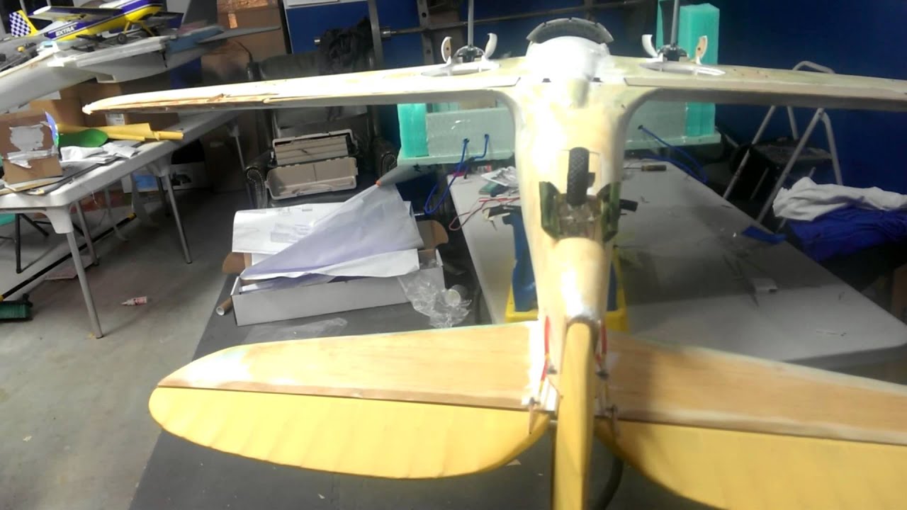
Attempt to visualize an airframe with shoulder-mounted anhedral wings for improved maneuverability and ground clearance, unlike the model shown above showing with its landing gear on what is actually the bottom of the P-40's low-wing configuration, a mid-mounted supercharged V8 engine, similar to Bell's P39 Airacobra, but with the prop shaft leading to a tail-mounted variable-pitch propeller so that a miniaturized radar can be mounted in its nose like any conventional fighter jet. Armaments might include a 20-30mm chain gun with 50-150 rounds of ammunition, 4 wing pylons for 4X Peregrine or Hellfire or Griffin missiles, or 4X Mk81 GPS guided bombs, or 4X 7-shot 70mm rocket pods, plus 2X AIM-92 Stinger missiles for self-defense.
WWII era fighters were typically low-wing monoplanes like the P-40, with conventional vs tricycle landing gear, because the heavy main gear could be mounted to the wing's main spar to absorb higher landing loads. The idea of attaching the gear to a mid-fuselage engine mount was not attempted. Tractor engine configurations permitted heavy engine / gearbox / propeller / autocannon combinations to be hung off the nose. Airborne radar was very new back then, so there was little thought given to mounting an air search radar in an ideal location. Twin engine night fighters did typically mount the radar antenna on or in the nose. Modern composite materials and aerodynamic drag reduction enables the use of shoulder-mounted cantilever wings. Stronger and more resilient modern steels enable the use of longer gear legs and tricycle gear configurations without excessive weight penalties.
A modern piston engine fighter should use tricycle gear to prevent ground loops. Any pusher engine configurations, such as the one I proposed, should always use a tricycle gear configuration to prevent prop strikes. Pusher engines eliminate prop wash effect over the empennage, which produces a more jet-like control response at low speeds. This can be viewed as a positive or negative. If the empennage is appropriately designed, then adequate control authority will be maintained right up to the stall, but the ability to induce a prop strike on takeoff will be greatly reduced.
Mini-IMP In Flight: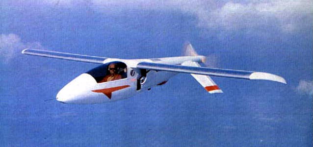
Fixed Gear Mini-Imp Variant on the Ground:
Even at 400mph, fixed vs retractable gear, with aerodynamic gear legs and wheel fairings, only results in a nominal speed increase of 5 to 10 knots.
Mini-Imp with Y-Tail and Variable Pitch Propeller:
Air-Cooled General Motors Corvair Mini-IMP Engine and Prop Shaft:
Testing the Mini-Imp, by M. B. "Molt" Taylor
Molt Taylor was an aeronautical engineer who worked for the US Navy during WWII. IIRC, he designed a drop tank for US Navy fighters operating in the Pacific and worked on weapons separation testing. He was the only aircraft designer to ever successfully achieve highway certification for a road-legal passenger car that was also a type-certificated light aircraft, and this work was performed during the 1950s, culminating in the so-called "AeroCar". While the project was technically dragged across the finish line, Taylor's company ran out of funding for series production. Following WWII, there was a thought process that middle class people living in the US would commute for work over longer distances using light aircraft and then drive said light aircraft's "fuselage" around town. In a certain sense, this is historically what happened, but the major airline services primarily provided city-to-city transportation using large turbine powered purpose-built hight speed aircraft, rather than slower but less costly owner-operator light aircraft seating 2 to 6 people. Some 20 years later, the Mini-IMP (Independently Made Plane) was Taylor's 1970s aviation cost reduction project undertaken to create a greatly simplified aircraft that could be made in a garage and required minimal numbers and types of different tools. Quite a bit of the design process revolved around airframe fabrication simplification. The "buy vs make" parts of the airframe were simplified to landing gear, engine mount, avionics, and radio.
Prior to designing and building the "Mini-IMP", Molt first designed and built a much larger and more expensive "IMP", similar in size to a modern piston engine fighter type aircraft, using a traditional aircraft engine with construction techniques and materials which were then-common in the aviation industry. This first pass at the cost and complexity problem was immediately deemed "too expensive / too complex" for a home builder. It was similar in cost and performance to early RV type aircraft. Following distribution of the Mini-IMP plans and key components such as landing gear and engine mounts, work on the "Micro-IMP" began, although never completed, which was an even smaller and more affordable plane. As far as lower cost materials were concerned, Molt also worked on "Taylor Paper-Glass" material, which combined a paper product with glass fiber, intended to be rolled and glued around a mold, similar to what modern fiber tape laying machines do for airliner fuselage and wing skin fabrication, to further reduce construction time and cost.
Anyway, that's the back story on the IMP / Mini-IMP / Micro-IMP and Taylor Paper-Glass... I never personally met Molt, but I did meet the man who eventually purchased his business and continued to distribute parts and plans after Molt retired and died in the 1990s. I never asked him about the AeroCar because it wasn't something I was interested in at the time. The new owner is / was himself a retired airline pilot and someone with a personal love of building light aircraft, and model aircraft as a child. He and his wife are as old as dust by now, too, if they're still alive.
The cockpit placement ahead of the engine was a deliberate design choice to provide superb visibility in all directions except directly behind the pilot. Since most other aircraft that might kill you during a mid-air collision are ahead (in front of), above (descending), or below (climbing) you. Nose-to-tail mid-air collisions do happen, but tend to be rarer. In any event, as can be seen in the photos, the wing and all other visual obstructions are located aft of the Mini-IMP's cockpit to maximize visibility. This is also an important design characteristic for all fighter-type aircraft to have.
The Mini-IMP uses NASA's GA(PC)-1 airfoil, which was a member of their "advanced technology" General Aviation (GA) airfoils designed during the 1970s. This was bleeding edge stuff when Molt included it in his designs. While they were primarily intended to reduce takeoff and landing speeds for light prop aircraft, they happen to perform decently at higher speeds, approaching the limit of what is legal below the flight levels, because the flaps in many implementations are reflexed upwards to reduce induced drag (from generating lift) at higher speeds. This is not the type of airfoil that should be used by higher speed fighter type aircraft, though. Between 75 and 275mph, though, they're pretty efficient. Back in the day, NASA worked on more projects to benefit GA. These days, they only seem to do gee-whiz projects for GA, and almost all of that is actually directed at commercial light aircraft, which makes sense in a way. EAA has pretty much taken over GA innovation where NACA and then NASA left off. There's no shortage of self-directed improvement projects that EAA members have undertaken, some of which ultimately ended up in the cockpits of commercial airliners.
The laminar flow NACA-66 series used on the P-51 were / are suitable for 200 to 450mph speeds, near-ideal for straight-line cruising, but weren't the greatest for maneuverability. Spitfires used modified NACA 2200 series airfoils, which provided a good mix of high speed drag reduction and maneuverability. Focke-Wulf's Ta-152H, a heavily modified variant of their famous FW-190, was ideal for straight-line speed at high altitudes, but again, not so great for maneuverability, nor use at lower altitudes for that matter. Wing loadings for 400mph sea level top speed fall between 40 and 50lbs/ft^2, which is 1/3 to 1/2 that of a supersonic tactical fighter jet, so takeoff speeds fall modestly below those of light biz jets, meaning 85 to 100mph. Biz jet takeoff speeds are 115 to 135mph. Initial climb rates are pretty spectacular for piston engines, meaning 5,000fpm+. This sort of sea level performance is suitable for turning inside highly maneuverable short-range IR-guided missiles and making aiming difficult for radar-guided autocannon air defense systems.
The Mini-IMP's control surface layout is modestly unconventional, but otherwise unremarkable. Various empennage arrangements were experimented with, including conventional, cruciform, butterfly, inverted butterfly, Y, and inverted Y. The inverted butterfly and Y tails were the ones which provided the best compromise between highest cruise speed and control near stall speeds during crosswind landings while making it difficult to deflect the control surfaces to the point of achieving a prop strike on takeoff. The airfoil chosen was a then-modern NASA design intended to both reduce stall speeds and achieve efficient cruise flight. Using a 65hp VW engine, the plane could achieve 175mph. Using the more powerful and ubiquitous 100hp Continental O-200 or 125hp GM Corvair engine, it could hit 200mph to 225mph. The airframe was relatively light yet strong, rated for aerobatic flight, and control forces remain light at higher speeds. The cockpit has lots of leg room, or at least the one I sat in did. The side-mounted control stick near the front of the right arm rest was comfortable to move in all directions. The ability to see out was much better than any Cessna I've flown, apart from directly behind. You really can see almost everything. It was possible to visually confirm that the main gear was down from the cockpit, but not the nose gear. Airflow into the cockpit in Texas heat? Not so great compared to the 152s and 172s because the prop is in the tail. I was baked after latching the canopy. It does feel like you're sitting on the ground, which you almost are. Entering was initially awkward, but exiting required no effort at all- open the canopy, stand straight up, and step over. Entering and exiting a scaled-up model with a V8 engine ought not require a ladder for most average height pilots, stepping on the wing, or other potentially dangerous gymnastics, a bonus for field operations.
Since "flying below the radar" will be necessary for survival of modern piston engine fighters, let's examine operating altitude ranges:
Radar Horizon vs Altitude
10m = 13-15km (8-9 miles)
100m = 40km (25 miles)
1,000m = 130km (80 miles)
10,000m = 400km (250 miles)
Anticipated operating altitudes for modern piston engine fighters should fall between treetop level and 3,000m to reduce or eliminate exposure to long range radar guided missiles associated with integrated air defense systems. Modern fighter jets fly at higher altitudes because they must, otherwise fuel economy suffers so greatly that combat radius and endurance are unacceptably affected. Piston engine aircraft can operate at significant altitudes, but a balanced approach to surprise / stealthiness / threat avoidance makes them more effective at lower altitudes where tactical fighter jets guzzle fuel and become more visible targets for shorter-range IR-guided missiles and autocannon fire.
The primary design criteria here are as follows:
1. Much lighter and less costly airframes and engines than turbine powered tactical fighters, with dramatically reduced fuel burn rates and consumption of less expensive gasoline vs kerosene fuel
Airframes fabricated from CNC machined lumber, plywood, and CNF from wood pulp are far less costly than synthetic composites and metals. Fuselages, wings, wing spars, empennage, and propeller blades will make use of wood and CNF laminate veneers that are pressed and heated to bond multiple layers of material together. CNC machines can then precisely mill wood parts. The use of plywood helps assure the average weight and strength of parts using these natural materials. To the extent practical, synthetic composites and metals won't be used. Certain fibers such as hemp and flax may be incorporated for specific use cases. Part of the crash structure for some Formula 1 cars now includes flax natural composites, specifically the seat. They're still working out how to make the entire survival cage built around the driver out of flax and hemp. The natural fibers are not as strong as higher grades of Carbon fiber, but other layers of materials such as Kevlar don't need to be bonded-in because natural fibers don't produce razor sharp shards of composite during a crash and do a better job of absorbing impact energy because they actually "crumble", sort of like tempered safety glass, rather than snapping like glass rods.
Amplitex Crash Box: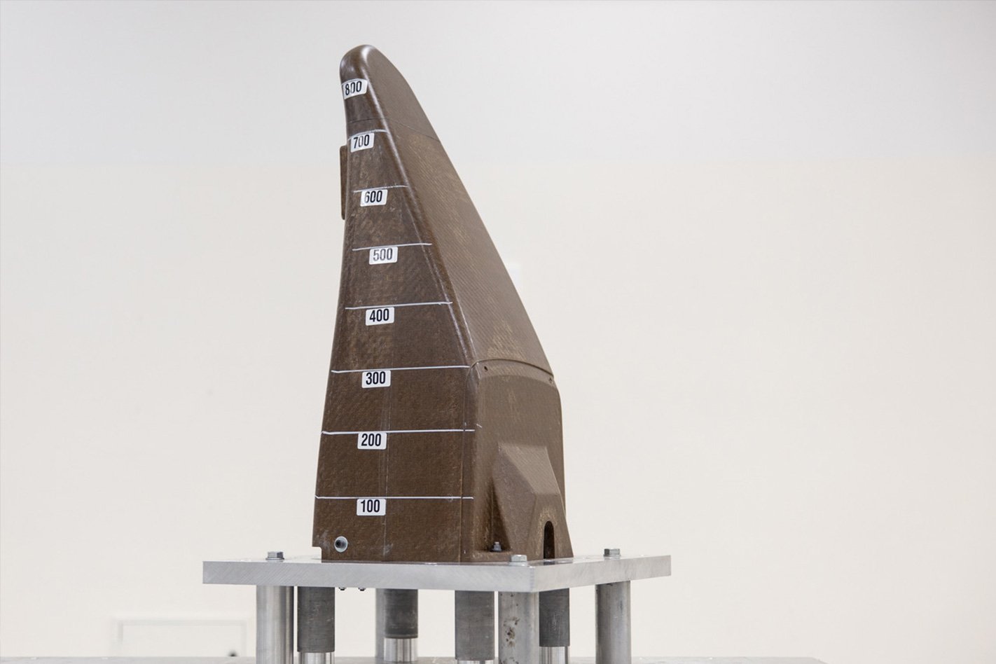
Amplitex Crash Box Testing: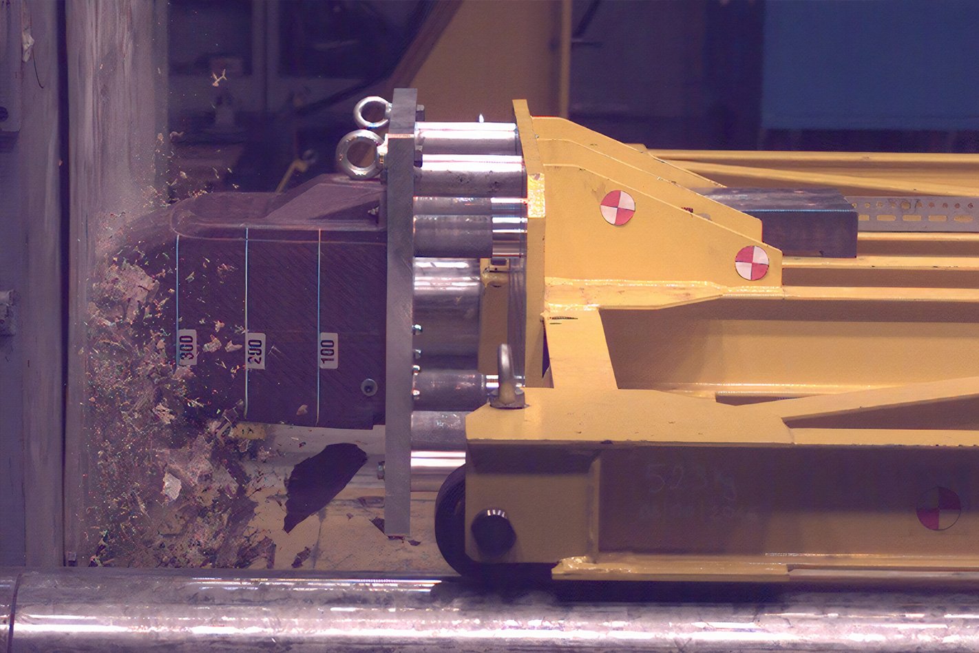
Amplitex Power Ribs:
The crash box shown above is still about 40% heavier than CFRP, but the seat is 9% lighter than an equivalent CFRP seat and 5X better at vibration dampening to reduce driver fatigue.
Synthetic spider silk is also nearing commercialization, and should be used for cockpit armor to capture shell and missile warhead splinters / fragments. Rather than some ridiculously expensive and ultimately futile attempt to armor the entire plane, it should instead be used to protect what matters- the aircrew. Any other use is questionable at best. The airframes and engines are nominal value expendable assets, as are all other weapons of war. Gold-plating any solution is counter-productive. On that note, any weapon system fielded against a competent enemy must be treated as a consumable, so technology must be applied only when it provides a meaningful advantage. If not, then there's no limit to the justification for sinking more money into any particular weapon or vehicle. You build to a standard which affords reasonably necessary mission capabilities and crew protection, then use better training, the element of surprise, and superior numbers to win.
2. Cruising speeds 100mph faster than the fastest helicopters and max speeds 200mph faster than the fastest helicopters
Ideal Speed Ranges
150 to 200mph: maximize range and endurance
300 to 350mph: evasive maneuvering
350 to 450mph: swift single passes against well-defended ground targets or engaging airborne targets
Higher flight speeds make more sense only for attacking integrated air defense systems, but all such attacks are executed with Mach 3 to 4 missiles with considerable standoff range. Autonomous combat drones already act as bait to force air defense system operators and tactical fighters to reveal themselves through defensive missile launches or face destruction.
3. More money is allocated to miniaturized sensors and armaments
Sensors illuminate targets, computers filter noise / clutter / jamming from true signal returns, and precise weapons efficiently dispatch them. This is where we should concentrate available funding.
4. Repair and complete replacement costs for the airframe and engine are nominal
The ability to lose an aircraft, or an entire squadron of aircraft, without that loss being unrecoverable, is a highly relevant advantage of turbine powered tactical fighters. If both Britain and Germany were only able to field a few squadrons of fighter jets, even if they did considerably more damage, the air war would've been over for both sides following the outcomes of singular daily battles.
5. Maneuverability is equal to or better than turbine powered tactical fighters
200 to 300mph of increased practical speed, at most, is utterly irrelevant to an inbound missile moving at Mach 2.5 to 4. We've already discussed why nobody flies faster than Mach 1.5 in air combat. Any speed over Mach 0.95 consumes fuel so fast as to be highly impractical in all but the most narrowly defined engagement scenarios, nearly all of them at high altitudes, even though it's technically possible to achieve using turbofan and turbojet engines. F-111s could and did fly at Mach 1.2 at treetop level, not using a phenomenal thrust-to-weight ratio typical of modern tactical fighters, only optimized aerodynamics in that speed range. Unfortunately, using this tactic rendered them highly vulnerable to air defense missile battery fire during the Viet Nam War, so several were lost to controlled flight into terrain attempting to evade missiles, a clear indicator of their inability to perform effective evasive maneuvers at such high flight speeds, despite a 7g maneuvering limit and generally excellent maneuverability.
Flying at high subsonic speeds near the ground to evade longer range radar tracking from integrated air defense systems precludes tight turns necessary for terrain and missile avoidance. Rapid downward altitude changes to capitalize on terrain masking to break radar locks are not possible. Rapid upward altitude changes only make the targeted aircraft more visible to threat radars. Whilst flying at higher altitudes renders both modern tactical fighter jets and WWII era propeller driven bombers functionally invulnerable to man portable IR-guided missiles and medium caliber radar-slaved autocannon air defense systems, they then become ideal targets for faster and potentially more lethal radar guided air defense missiles with significant ranges and powerful warheads. Stealth technology then made achieving a radar lock against a fighter jet operating at higher altitudes and high subsonic cruising speeds much less likely at extended ranges, but their IR signatures are unmistakable. If it ever becomes practical to perform volume search using powerful long range electro-optical sensors, then radar stealth becomes far less effective.
Maser-based radars will ultimately render existing radar stealth technologies ineffective. The stealthy features of the F-22 may reduce the radar return signal strength by 1,000X when compared to a similar non-stealthy airframe, but per unit area a maser also delivers at least 1,000X greater microwave radiation intensity. Deployment of maser-based air search radars implies that we revert back to using lower altitudes and flight speeds in conjunction with terrain or radar horizon masking to hide from vastly more powerful maser-based air search radars that can still lock-up a stealthy tactical fighter jet almost as easily as non-stealthy jets. Geometry provides most of the radar signature reduction (deflecting inbound radiation in any direction except directly back at the source emitter), not RAM, which mandates another 3 orders of magnitude in radar return strength reduction to maintain radar signature levels similar to those already achieved by the F-22. That's likely impossible, so a 0.001m^2 F-22 radar target is about as visible to maser-based air search radars as a 1m^2 radar target is to a conventional X-band air search radar today. Modern X-band radars can track 1m^2 targets from over 200km away, so existing radar stealth technologies won't sufficiently reduce tracking ranges against maser-based radars to remain militarily useful.
If radar and infrared signature reduction measures can't passively protect our military aircraft, then we must develop and deploy active protection systems to destroy inbound missiles. Our armored ground combat vehicles already use these technologies. Sufficiently accurate autocannon turrets should be able to reliably destroy inbound missiles, making the entire stealth vs non-stealth argument irrelevant on cost grounds, irrespective of future application of new radar and electro-optical tech improvements. Ground-based autocannon systems are already used to intercept inbound artillery shells and missiles. Using a moderately successful implementation, air defense system operators might expend far more money launching missiles at piston engine bombers flying at 20,000ft and 200mph than the aircraft are intrinsically worth, prior to achieving a kill. That makes everyone's near total reliance on defensive and offensive missiles an impossible math problem. We then revert back to using cannons and guided glide bombs to saturate a target area with weapons so that at least one shell or bomb will destroy the target. Glide bombs dropped 10 miles away keep the launching aircraft outside the engagement envelope of lower cost high powered cannons and shoulder-launched IR-guided missiles. Nominal cost kamikaze drones already capitalize on this missile math problem, but unmanned combat drones with similar size physical size / weight / payload-to-distance capabilities as crewed tactical fighters cost every bit as much as crewed fighter jets, frequently substantially more than crewed aircraft, which is why the US military has retired so many of their higher tier capability combat drones. All their supposed cost reductions never materialized. This was re-proof that airframe cruising speed, therefore engine cost, operating empty weight, therefore materials costs, plus sensor and weapons capabilities, drives procurement and operating costs, not the presence or absence of a crew member aboard the aircraft.
ATK's LW25 lightweight 25mm autocannon:
LW25 Dual-Feed Turret:
LW25 capabilities:
LW25 Integration on SAAB Trackfire RWS
The 68lb LW25 has a dual-feed system, so a single-feed system suitable for aircraft defensive turrets could be as light as the 63.5lb M3 .50 caliber aircraft machine guns used aboard US aircraft since WWII. LW25 cyclic rates are lower than M3s, but that might not matter as much when using programmable airburst munitions capable of high precision distance-based fusing in conjunction with low-cost / lightweight / short-range (5-25km) / high resolution imaging radars with AI-enhanced control software capable of automatically tracking and engaging inbound missiles. If the LW25 is insufficient, more powerful higher velocity autocannons are available, such as the M230, at the expensive of weight and cost. Single barrel chain guns like the M230 cost about $25K per copy, less for the smaller caliber models and more for the larger caliber models, more expensive than M3s but more effective with appropriate munitions and far less costly than Gatling autocannons like the M197 and M61, at $250K per copy.
If autocannons alone prove insufficient for stopping inbound missiles, then Stinger missiles are an alternative, much more costly than cannon shells though much less costly than large radar-guided air intercept missiles. Fiber lasers will eventually become viable, too. What likely won't become a more practical option is sinking ever-greater sums of money into individual airframes and engines for 200 to 400mph worth of usable speed difference while facing inbound weapons moving 2 to 4 times faster than a turbine powered tactical fighter can manage without rapidly exhausting its onboard fuel supply.
#18 Re: Not So Free Chat » Politics » 2026-02-11 17:04:34
Jesse Van Rootselaar, 18, ID’d as transgender ex-student behind Tumbler Ridge mass shooting
9 people were apparently killed and 25 others injured between a prior shooting at or near the suspect's home, which involved shooting their mother and brother, and the Tumbler Ridge Secondary School, British Columbia, Canada, where he / she / they / them / this / that / the other was previously a student.
#19 Re: Human missions » space x going to the moon instead of mars » 2026-02-11 04:18:16
Oldfart1939,
ULA's so-called "crasher stage" concept landed a RL-10 powered Centaur upper stage on the moon using thrusters affixed to all four corners of the vehicle so that the upper stage could land on its side, which was a very stable landing configuration, relative to a vertical Centaur-based lander similar to the one proposed by Lockheed-Martin, or SpaceX's "more ridiculous" super-sized version.
This 2013 article from Jon Goff, over at Selenian Boondocks, describes his take on the concept:
Centaur UnCrasher Stages for Simplified Lunar Landings
#20 Re: Not So Free Chat » Cost-Effective Credible National Defense » 2026-02-11 04:05:11
During WWII, the British De Havilland Mosquito fighter-bomber was fabricated from birch and poplar aircraft grade plywoods with balsa wood cores. When compared to similar American / German / Japanese Aluminum alloy airframes, the Mosquito was substantially lighter and stronger for a given weight.
That was the real reason it was so difficult for the Germans to deal with it. A lighter natural composite airframe means more speed and maneuverability for a given engine power and combat loading. De Havilland's Mosquito was enough of a problem for Germany's Luftwaffe that Focke-Wulf built their own wooden fighter-bomber, the Ta-154 Moskito. The Ta-154's airframe relied upon a then-advanced phenolic resin film used to bond sheets of aircraft plywood together, so-called "Tego film".
De Havilland Mosquito B Mk.XVI
Crew: 2
Engines: 2X Rolls-Royce Merlin 76/77 liquid-cooled V12s; 1,750hp each (2,000hp w/higher Octane fuel)
Empty Weight: 14,300lbs
Max Takeoff Weight: 25,000lbs
Max Speed: 415mph at 28,000ft
Wing Area: 454ft^2
Internal Fuel: 450 gallons
Range on Normal Internal Fuel: 1,300 miles
Service Ceiling: 37,000ft
Normal Max Bomb Load: 4,000lbs
Normal Defensive Armament: 4X 20mm cannons
G Limits: +8G/-3G
Grumman XTSF-1 (Fighter-Bomber Derivative of Late War F7F Tigercat)
Crew: 2
Engines: 2X Pratty & Whitney R-2800-22W Double Wasp air-cooled radials; 2,400hp each
Empty Weight: 17,288lbs
Max Takeoff Weight: 26,171lbs
Max Speed: 414mph at 18,600ft
Wing Area: 500ft^2 (455ft^2 for the F7F Tigercat)
Internal Fuel: 400 gallons
Range on Normal Internal Fuel: 975 miles (1,200 miles for F7F Tigercat)
Service Ceiling: 36,500ft
Normal Max Bomb Load: 4,000lbs
Normal Defensive Armament: 4X 20mm cannons
G Limits: +6G/-2.5G (applicable to F7F Tigercat; 7.5G tested in a 525mph dive)
Notes:
Approximately 700lbs of XTSF-1's empty weight is directly attributable to its heavier R2800 radial engines. Merlin engine dry weight with radiators and fluids was near 2,000lbs, so the 1,640lb engine dry weight is a bit deceptive since ready-to-fly installations were much heavier. R2800s weighed in at 2,360lbs, without engine oil or exhaust piping, which varied between aircraft. However, XTSF-1's airframe weight, less engine dry weight, was still 12,568lbs. Mosquito's airframe weight, less engine dry weight, was 11,020lbs. That means XTSF-1's all-Aluminum airframe was 14% heavier and range was 75% of a wood composite Mosquito airframe. If you include radiators for the Merlins, then Mosquito's airframe weight is about 17% lower than XTSF-1.
Max takeoff weight for XTSF-1 is appreciably higher, but the F7F Tigercat's airframe it was based upon was 25,720lbs, very close to a Mosquito, and a Tigercat's normal max range was 1,200 miles, so 100 miles short. Equal internal fuel capacity for a F7F would increase range over a "standard" Mosquito, but Mosquito variants were built with larger wing tanks for increased max range. If XTSF-1 and Mosquito both carried 450 gallons of internal fuel, simple math says XTSF-1's range increases to 1,097 miles, still 15.6% short of a Mosquito.
Both Britain and the US used the same 20mm Hispano autocannons with very minor dimensional variations for a handful of internal parts, but they were outwardly identical weapons and weapon weight was almost identical. I can't speak to the weight of shells, propellants, and casings. In general, America paid more attention to the weights of casings and shells than other nations because we had spare engineers to do that.
How might we apply the lessons of WWII airframe design decisions to modern piston engine fighters?
For fabrication of airframes, we can still use natural composites made from light hardwoods, such as poplar and pine, combined with a brand new engineered fiber material known as Cellulose NanoFiber (CNF) film, which is derived from processed wood pulp. CNF is our modern day equivalent to Germany's Tego film. Tensile strength of CNF film ranges between 100MPa and 300MPa, dependent upon processing pressure. 1,700bar presses are required to make 300MPa films. CNF film can then be pressed or epoxied to thin wood veneers or plywood to dramatically increase the tensile strength of wooden structures. The strength-to-weight ratio of CNF film is about equal to the strongest Aramid fibers.
People who fabricate fiberglass composite boats for a living know that wood cores combined with a fiberglass overwrap for tensile strength results in multiple hundreds of pounds of weight savings, for equivalent strength, over pure fiberglass alone, which is much heavier per unit volume than any kind of wood. While GFRP is a superb material for tensile strength, adequate stiffness is achieved only by using thicker but much lighter core materials.
The key material property missing from CFRP and GFRP is stiffness, rather than tensile strength for a given weight, which is where they truly excel. It's fairly common to use Aramid honeycomb cores and various kinds of synthetic foams in conjunction with CFRP or GFRP to reduce weight. The problem with lower density foams and honeycomb cores has always been bond strength and the tendency of foam to buckle and crack under load. Low density hardwood or high density soft woods can minimize that problem while improving toughness.
Whereas CFRP combined with Aramid fiber honeycomb cores might have their place for very large and very high strength structures required by modern airliner and fighter jet wings / empennage / fuselage structures, they're also very expensive overkill for much lighter and smaller piston engine airframes. The performance increment they provide is marginal. They're most frequently applied to light civil aircraft to minimize engine power required for a given cruise speed and payload-to-distance. This is a less important design factor for much higher-horsepower military aircraft. A well-engineered natural composite structure is going to be strong and light enough to get the job done at greatly reduced cost, relative to metal and synthetic composites.
Composite Material Bulk Densities
Carbon Fiber Reinforced Plastic (CFRP): 1,500 to 1,700kg/m^3
Glass Fiber Reinforced Plastic (GFRP): 1,500 to 2,200kg/m^3
Poplar: 455kg/m^3
Shortleaf Pine: 570kg/m^3
Slash Pine: 655kg/m^3
The bulk density values for CFRP and GFRP are dependent upon fiberglass fabric type, resin matrix, and fiber fill ratios. The wood densities are industry average dried weights based upon 12% moisture content following kiln drying of the lumber. CFRP is about 3X heavier than wood, which means adequately stiffened structures will either be very heavy or use much lighter core materials.
Aircraft which are largely "wood and fabric" also possess another important material property for modern air warfare- they tend to have significantly reduced radar returns in comparison to CFRP, GFRP, and metals, even without special shaping to redirect the radiated energy away from the radar transceiver. This is not to suggest that a wood airframe is automatically better than all other stealth technologies, namely deliberately applied airframe shapings and special radar absorbent material coatings, but rather that without spending piles of cash on advanced stealth tech, you can still achieve a substantial radar return reduction with greatly reduced cost and effort. Radars provide stronger returns when directed against higher density metals and synthetic composite structures. This simple fact has been known since the inception of air search radar technology.
If your nation doesn't have an unlimited defense budget to spend on eye-wateringly expensive tactical fighters and various other turbine engine aviation assets, the alternative can still perform quite well in 90% of all real world air combat, at price points two orders of magnitude lower. Attacking integrated air defense systems and engaging stealth tactical fighters in air combat are the only notable exceptions.
A modern military still requires stealthy turbine powered aircraft or cruise missiles to destroy an enemy's integrated air defense systems and stealth tactical fighters on the ground, but once their irreplaceable air combat assets have been depleted, they cannot replace them fast enough to meaningfully affect the outcome of a war.
Consider how fast Russia's entire inventory of tens of thousands of armored vehicles were completely depleted during their war with Ukraine. Specific battles resulted in losses of over 100 units. They're actively making more T90s to replace the T54s / T55s / T62s / T64s / T72s / T90s lost in that war, but haven't kept pace with losses. Manufacturing modern or semi-modern main battle tanks is at least an order of magnitude less difficult and costly in comparison to a modern fighter jet, stealthy or not.
In a war where all aviation assets are in short supply, with a maximum replacement rate of perhaps one squadron per month, assuming the fighter jet factory hasn't been bombed or had its electricity cut off because the nearby power plant was bombed, you are never going to keep pace with a nation manufacturing an entire air wing per month. Tactical fighter jets are fantastic machines for air combat, but will never be in more than one place at one time. In a full strength squadron with 12 jets, 6 are merely flyable at any given time and 2 to 4 will be fully mission capable. 4 fighter jets are not going to win any air battles against an entire air wing of piston engine fighters equipped with the same sensors and weapons. Even if said fighter jets never suffer a loss in air combat, which is a statistical impossibility, eventually all aircraft must land, and then all their fantastic combat capabilities are meaningless while they're parked on the tarmac.
Piston engines powering wooden planes isn't such a crazy idea after you examine how fast all fighting machines get destroyed in modern wars. When individual aircraft have become so expensive and time consuming to manufacture so as to be treated as irreplaceable national assets, you lose less sleep over their inevitable loss in war when your nation still has available aviation assets rather than none.
There are vanishingly few "wunderwaffe" in real life. Nuclear weapons are outliers. No other singular technology has proven decisive, to include stealth. Air power alone has yet to win any war. Surprise can be decisive, and frequently is. Germany's V1s and V2s had zero effect on the outcome of their war. Germany's operational fighter jets had zero effect on the outcome of their war. Germany facing several squadrons of planes for every plane they could put in the air, and an entire brigade of armored vehicles for every vehicle they fielded, absolutely affected the outcome of their war. Logistics wins all modern wars, not technology alone. This has been the case since WWII and isn't likely to change in the near future.
Technology is important in many ways, but all the hypersonic weapons Russia fired at Ukraine haven't affected the outcome of the war in the slightest. The extreme cost of turbine engines and hypersonic weapons makes them useful tools only when they solve specific combat problems using additional speed. Speed alone has yet to render all other weapons and tactics obsolete or obsolescent. Despite the availability of large numbers of turbine powered aircraft and weapons, air superiority hasn't been established over Ukraine after 4 years of fighting. Future wars between peer level adversaries may never see establishment of air superiority by one side or the other. Any opponent that has defense-in-depth and realistic combat training is unlikely to "fold" after losing a major battle or even a string of major battles. When the will and means to continue fighting exists, we revert back to WWII style attritional warfare by default. Pouring incredible sums of money into dwindling numbers of exceptionally expensive weapon systems is not a good strategy for winning that kind of war.
#21 Re: Human missions » space x going to the moon instead of mars » 2026-02-10 16:52:14
GW,
A larger Starship should be cheaper to fly than a Falcon Heavy. Falcon 9 / Falcon Heavy are both reliable rockets, and fit-for-purpose, but the marginal cost of flying a mass produced Starship will likely be much lower than the Falcon series because SpaceX is creating the infrastructure for Starship mass production at a scale it never did for Falcon and Dragon. SpaceX also failed to man-rate Falcon Heavy, which is a problem. Maybe not a big one, but an impediment nonetheless. Atlas V had the same problem, which ULA later rectified, but only at extreme expense. Regardless, fuel costs are going to become significant under this new operating regime of daily or even hourly launches. A rocket flown that way must burn the cheapest fuel money can buy, and that's Methane.

A Falcon Heavy flight is around $100M and the independent analysis math on a Starship flights says marginal cost is around $10M per flight, and SpaceX could charge between $20M and $100M per flight while undercutting all existing orbital launch vehicles by a considerable margin.
Why launch a crew aboard one marginally capable heavy lift rocket when you can launch 10 super heavy lift rockets for the same price?
A 2,000t mass allocation is a pretty robust mission package, is it not? You ought to be able to do quite a bit of science with that.
$200M to $1B to deliver 2,000t IMLEO (double the mass of the ISS), for a crewed exploration mission, has to be one of the cheapest exploration missions in living memory. If they only charged $20M per flight, then the mission can be 10,000t IMLEO for $1B. Putting a Ford Class aircraft carrier's equivalent tonnage (110,000t) into LEO, costs less than building the actual USS Ford. I have to believe that Elon Musk and SpaceX understand that all commercial and colonization missions revolve around cost per ton delivered and little else. If government budgets are restricted in the future, then all future exploration missions will be similarly budget-constrained. There will still be more than enough dollars for exploration missions.
SpaceX, Blue Origin, and our other aerospace primes should be focusing on creating a "shopping catalog" of mission hardware sets, so that anyone who is willing to foot the bill can select from their catalog and walk out with the hardware required to perform a specific mission.
I agree with the idea about using a space tug, but not one that requires constant refills of cryogenic liquids. Tugs should be used for slow but inevitable "heavy hauls" of vehicles and cargo to higher orbits using electric propulsion, wherein time spent spiraling-out is a non-issue. We can afford to use pure chemical propulsion for rapid transit with crew members to GEO. The radiation fluence at the orbital altitudes involved is nowhere near what it is within the heart of those captured proton belts. NASA has worked on ZBO tech for a very long time now. It's either time to get that up and running if we're going to do tugs using cryogenic liquids, or to move on to other more productive propulsion technologies. If someone gets ZBO to work at a later date, then we'll circle back to it.
RocketStar has developed and flown in space their FireStar aneutronic "fusion afterburner" for electric ion engines. It improves thrust output by 50%, so nothing too spectacular, but Isp is 7,300s and the primary propellant is water. All they're doing is ramming high energy protons from the ion engine exhaust into Boron atoms and fomenting a very rapid radioactive decay chain starting with Carbon-12, a serendipitous exploitation of unique atomic properties of Boron and water, that briefly uses fusion as a radioactive decay catalyst, and dumps the heat into water vapor, creating more thrust in the process. The process is highly electrically efficient, and that is what matters, because it consumes electrical power rather than producing any from fusion. The extra power doesn't even come from fusion, only the rapid decay of Carbon-12. Work began back in 2014 from the results of an AFRL propulsion experiment for their spy satellites, IIRC. The specific phenomenon being exploited was understood and known to occur, but nobody thought to use it to generate additional thrust from an ion engine. It took RocketStar's people about 10 years from basic concept to working ground engine demonstrator in 2024, followed by an in-space demo in 2025 about a very small 6U Rogue Space Systems commercial micro satellite, named "Barry-2", primarily intended to demo COTS computer hardware in a high radiation environment. I believe it was launched aboard a Falcon 9 as a tertiary payload, March 15th, 2025, with the satellite's designator being OTP-2. NORAD ID was 63235. So far as I know, it's now defunct.
I think a tiny amount of Boron mixed into water is a suitable propellant for in-space propulsion using existing ion engines. Even gases like Argon or Oxygen or Nitrogen are more difficult to store and costly to obtain in pure form, in comparison to Boron and water.
All the more advanced fission and fusion concepts look very promising for high-thrust applications, but they're also very difficult to do safely and none of them are ready to use in the near term, which means they'll need to be worked into the program over the next 10 to 20 years. A water propellant 7,300s Isp ion engine with 2,900N of thrust per MWe of input electrical power is a nice consolation prize in lieu of Helicity's "real" Fusion Drive or BWXT's NTR. As I said before, baby steps. Fusion catalyzed Carbon-12 radioactive decay is good enough for now. Learn to accept the consolation prizes and move forward using what we can do over the short term for in-space propulsion. Real star-like fusion and fission reactors the size of trash cans pumping out a gigawatt of power are just really hard to do properly when they're not national priorities. We'll eventually make them work the way we want them to, but not in our immediate future.
In the mean time, we can still put together a pretty spectacular exploration class mission using what we have working right now or will have working within the next 5 years. I think it's reasonable to assume that Starship will be up and running 5 years from now. 5 years of FireStar development would deliver a MW-class pulsed plasma ion engine up and running. We've already ground tested several MW-class ion engines, and have decades of development work behind them. We're not working with a completely new technology here. It's a novel application of existing technologies, but purely operates on existing tech nonetheless.
If we can achieve a direct transfer to a high orbit using a lightly loaded (personnel only) Starship, with no docking or transfer until you get to GEO, isn't that simpler and faster, even though a space tug would still work?
For a chemical space tug, what major part of the upper stage vehicle mass do we get to leave behind?
Won't it be limited to the heat shield only?
#22 Re: Human missions » space x going to the moon instead of mars » 2026-02-09 14:02:48
A ship using ion propulsion can boost itself into a stable GEO without any crew aboard, and then a minimally loaded Starship V3 can dock with it at the far edges of Earth's Van Allen Belts, where radiation exposure is minimal. At 100kg per crew member, 100 crew members represents a 10t payload per Starship, aboard a vehicle that nominally delivers 200t to LEO and 15t to 25t to GEO, without refueling. That is more than sufficient payload performance to reach GEO. The time spent spiraling out from GEO to TMI is minimal.
If Starship V3 still requires 1 refueling event to return to Earth with an acceptable performance margin, then that still makes more economic sense than refueling it a half dozen times or more to send a Starship all the way to Mars. That means in-space electric propulsion is both feasible and practical using a modest but meaningful modification to how we perform crew transfers to larger / heavier / slower / but better-equipped interplanetary ships with artificial gravity and mass margins for additional crew provisions.
There is no hard requirement for the interplanetary ship to perform impulsive maneuvers to clear the Van Allen Belts swiftly when nobody is aboard. From a ship design standpoint, it's better if interplanetary ships don't perform impulsive maneuvers because then they don't need to withstand an additional set of significant mechanical loads applied to them by high-thrust engines.
If your propulsion options allow you to maximize speed or payload, go for payload. Enormous carrying capacity precludes the need for speedy transits. The slow boat to China still makes it to China, and still arrives carrying an enormous payload. We need bulk freighters to safely send people to Mars, not Ferraris.
If we insist on using LOX/LCH4 or LOX/LH2 propulsion, then over 90% of all the mass we deliver to orbit for Mars missions, assuming Earth orbit to Mars orbit and then back to Earth orbit transportation, is propellant. Using electric propulsion achieving an Isp of 2,500s or greater, at least 50% of the mass we ship can be anything except the propellant. If one of the primary mission objectives is to deliver things other than propellant, then in-space electric propulsion is a non-negotiable hard requirement.
It's not practical to build these enormous AI data centers in orbit and do Mars missions when every Mars mission requires at least a half dozen flights per outbound transit. At some point, our fuel consumption starts impacting other sectors of our economy, and that's where the Mars missions will end, because someone will invariably point out that there is no massive immediate economic return on investment. A Mars colony is a slow-burn investment into the future of humanity through enhancement of our reach into our own solar system. A large Mars colony is a long term side-hustle that pays off in the mid to far future, likely in ways we don't yet fully comprehend.
All the tech applicable to a Mars colony will eventually pay into real-life Star Trek starships that we can use to colonize planets orbiting nearby stars. If we don't have the interplanetary transport and colonization tech ready to go by the time AI figures out how to bend spacetime, then we're going to squander another 25 to 50 years experimenting with how to live on another planet before we can do anything at all with our snazzy new Star Trek "real-life starships", apart from taking pretty pictures. All the "baby steps" we take to get to that point are just that- a toddler learning to crawl-walk-run. Capitalizing on existing and emerging electric propulsion is merely one more of those baby steps.
#23 Re: Not So Free Chat » Politics » 2026-02-09 12:39:26
SpaceNut,
If leftists want our Police to treat them more humanely, then they should stop chasing them around, throwing things at them, spitting on them, vandalizing their vehicles, threatening to murder them in their sleep, and threatening to murder their families. Those are not the behaviors of someone who wants "de-escalate" anything.
#24 Re: Not So Free Chat » Politics » 2026-02-08 14:45:01
SpaceNut,
What I care about is that the State of Minnesota's Governor, the Minneapolis Mayor, and a lot of Somalis, all took part in a TEN BILLION DOLLAR MEDICAID FRAUD!
Only Democrats actually care about skin color, which is why they talk about it all the time. Everyone else is waiting for Democrats to course-correct to a set of core governance principles that don't involve blatant criminality.
If every single one of the people we imported from Somali were blonde-haired blue-eyed bikini team models, and they were involved in the same fraud schemes, then I would still want to deport every last one of them.
America is not going to become an "anything-goes" communist dystopia because a minor fraction of the population wants to agitate for it on the basis of irrationality and general ignorance of history.
You know who absolutely does deserve American citizenship?
All those Afghanis who fought for America, and for their own freedom, that President Biden's administration straight-up abandoned to the Taliban, should have been scooped up and spirited away from the hell hole the Taliban created.
How about all the Kurds and Yazidi who fought tooth-and-nail against ISIS?
Surely they are more deserving of the privilege of being an American than the repulsive assortment of rapists and murderers President Biden's administration imported into America.
#25 Re: Science, Technology, and Astronomy » Fighter jets: F-35 vs Gripen vs Avro Arrow » 2026-02-08 13:42:16
RobertDyck,
From Reddit user "Live_Menu_7404":
There has been a recent report by Global Defense Corp on YouTube claiming Saab will offer the Gripen E with the Eurojet EJ230 instead of the F414-GE-39E/RM16. Is there any truth to this claim? Is it feasible and sensible from a technical standpoint and what would this entail? What are the associated risks?
From Reddit User "RobinOldsIsGod":
That proposal goes back to the late 1990s, when Germany first proposed replacing the Gripen-C's RM12s with EJ230s. Typhoon was supposed to have thrust-vectoring engines, but those were canned due to budgets. Damn shame too, that would have made the Typhoon f'n awesome. But today? AFAIK, the EJ230 doesn't actually exist beyond a prototype taken to trade shows.
Now, sticking an EJ200 in a Gripen-C would be a godsend to that plane as it's got more thrust than the Gripen-C's RM12. But putting an EJ230 into a Gripen-E would likely result in a thrust loss. Not only does the EJ200 produce about 2,000 lbs less thrust than the F414/RM16, but thrust vectoring nozzles makes the engine itself heavier. That ain't great when the Gripen-E is already roughly the empty weight of a Blk 30 Viper but only has about 80% of the the Viper's thrust. Thrust has always been a LIMFAC on the Gripen series. The Dassault Rafale is basically what Gripen should have been; slightly larger with a much larger weapons and fuel load and generally better performance.
Outside of angry Canadians (just everyday people, not anyone with actual knowledge) reposting each other and having a crisis over the idea of EJ-powered Gripens and one YouTube channel with AI V/O that damn near gave me cancer...I can't find any corroboration to Global Defense Corp's claim. Maybe this is something that Saab has pitched again to drum up sales interests after Citrus Caligula's F-47 comments, but even Saab knows that their delta-winged Ikea F-20 is not in the same category as the F-35, much less a a twin-engined, 6th VLO fighter or even the KF-21 for that matter.
Remember those CFTs that were demo's on a Super Hornet a few years back? Know why you never see them in use? Because the Navy didn't fund their development. And even though there was interest from some potential foreign operators, they weren't willing to foot the bill for them once the Navy passed on it.
So Saab can offer it all they want, but someone's going to have to pay for the EJ230's development from prototype to production engine and the integration of it in the Gripen-E/F and all the associated flight testing.
Honestly, it's 2025 and Gripen first flew in 1988. This would have been great in the 90s on Gripen-C, but here we are on the verge of 6th Gen GCAPs. Sweden should have stuck with that instead of trying to get more blood out of this stone.
GE offers an up-rated F414 as well:
GE F414 Enhanced Engine