New Mars Forums
You are not logged in.
- Topics: Active | Unanswered
Announcement
#76 2021-11-18 14:47:29
- SpaceNut
- Administrator
- From: New Hampshire
- Registered: 2004-07-22
- Posts: 29,850
Re: Gravity Energy Storage
That unusable well for drinking and more is at a depth of 280 ft and its still cold (below 50' F) even after passing through the bed rock that is 60 ft down...
So a well depth that is a 1000 ft is going to be a hard sell....
edit
The pipe is less than a foot in diameter at the top of the well that is driven into the bedrock.
There are wells that are deeper when they can not get enough water pressure and its used as a reservoir to draw from.
Offline
Like button can go here
#77 2021-11-18 18:22:41
- tahanson43206
- Moderator
- Registered: 2018-04-27
- Posts: 23,353
Re: Gravity Energy Storage
For SpaceNut ... re #76
Thanks for providing the 280 foot real world number!
I asked Google to convert that number to meters, and it came up with:
https://www.google.com/search?channel=f … +to+meters
280 feet = 85.344 meters
That gives me a target to shoot for tomorrow, when I try lead as the counterweight.
I'm confident the depth will be less than iron at 106 meters, but whether it will get all the way down to 85 meters is a question.
I'm looking forward to finding out.
(th)
Offline
Like button can go here
#78 2021-11-19 07:22:49
- tahanson43206
- Moderator
- Registered: 2018-04-27
- Posts: 23,353
Re: Gravity Energy Storage
The post for lead was updated this morning. See link in Post #1 of this topic if you are interested in seeing the calculations.
The result is:
After consultation with www.WolfRam.com, we have assurance that the equation for the current problem is X * Y = Constant.
The constant in this case is 1941
The solution is: Square Root of 1941 * two, or 88 meters
That number compares to 175 meters for concrete.
The height of a shaft able to deliver 2 Kw for 24 hours, using a counterweight made of lead in the form of a cylinder 1 meter in diameter, is 88 meters. The height of the cylinder is ½ of 88 meters, and the drop distance is ½ of 88 meters.
This is more than the 80 meters of the water line that SpaceNut reported for his property, but way less than the height needed for concrete.
The shaft length could be reduced by increasing the diameter of the shaft from one meter. No doubt there is a sweet spot where the cost of digging the shaft vs the cost of the pipe in diameter and length is optimized.
Since lead is the densest material that is practical for this application, I offer 88 meters as the maximum depth for a Gravity Energy Storage device that is designed to employ a counterweight 1 meter in diameter.
(th)
Offline
Like button can go here
#79 2021-11-21 14:53:16
- tahanson43206
- Moderator
- Registered: 2018-04-27
- Posts: 23,353
Re: Gravity Energy Storage
The following is a snapshot of data reported earlier in this topic. It summarizes calculations for concrete/granite, iron, lead and an alloy
The alloy was computed with a cylinder radius of .6 instead of .5. The shaft height for this configuration is less than 80 meters.
80 meters is the target I was aiming for, given a real-world report from SpaceNut of a water well drilled locally.
Repeating Calliban re Concrete cube:
Quotation from Calliban:
2kW for 24hours is 48kWh = 172.8MJ. 1kg raised 1m = 10J. Let's us assume a 3m raise. That's 30J/kg. Concrete bound granite rock has a density about 3000kg/m3. So 1m3 raised by 3m = 90KJ. The total volume of rock needed would be just shy of 2000m3, or a cube 12.4m aside. A lot larger than an average house and not very easy to achieve.
End Quotation.
Begin Concrete using estimated density of 3000kg/m3:
Concrete density (about) 3000kg/M3 << The amount is a bit high but convenient
So 1 cubic meter of concrete raised by 3 meters is 3000 kg * 30J/kg gives 90,000 Joules or 90 KJ
The energy of a cubic meter of concrete raised 3 meters is 90 KJ which is .09 MJ
Volume computed for 172.8 MJ /.09 MJ is 1914 cubic meters.
End Concrete
Cube root of 1914 is 12.4 and change [12.419697 per calculatorsoup.com]
Height of a cylinder of radius .5 and volume 1914 is: 2437 per calculatorsoup.com
The product of 2437 and 3 is 7311 (This is the corrected constant for concrete)
The square root of 7311 is 85.5 and change
The total shaft height for a concrete counter weight is 85.5 * 2 or 171 meters.
Begin iron using reported density of 7860kg/m3:
Compute mass of a cubic meter of iron:
Iron density 7860kg/M3
So 1 cubic meter of iron raised by 3 meters is 7860 kg * 30J/kg gives 235,800 Joules or 235.8 KJ
The energy of a cubic meter of iron raised 3 meters is 235.8 KJ which is .2358 MJ
Volume computed for 172.8 MJ /.2358 MJ is 732.8 cubic meters.
End iron
Cube root of 732.8 is 9 and change [Per calculatorsoup.com, 9.01561077]
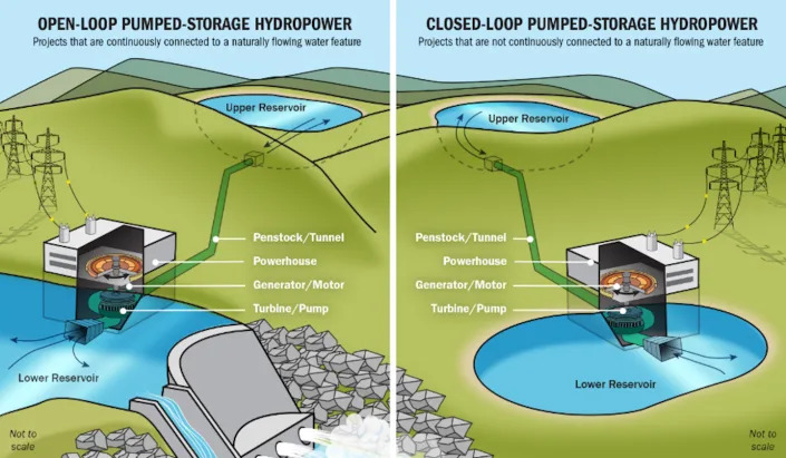
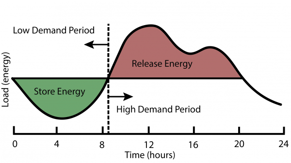
Height of a cylinder of radius .5 and volume 732.8 per calculatorsoup.com is: 933 meters
Per calculatorsoup.com, a cylinder of radius .5 and height 933 has a volume of: 732.776486
The product of 933 and 3 is 2799. (this is the corrected constant for iron)
The square root of 2799 is 52.9 and change. The total shaft height for an iron counterweight is: 106 meters
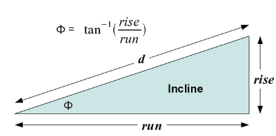
Begin lead using estimated density of 11,343kg/m3:
Compute mass of a cubic meter of lead:
Iron density (about) 11,343kg/M3
So 1 cubic meter of lead raised by 3 meters is 11343 kg * 30J/kg gives 340,290 Joules or 340.29 KJ
Volume computed for 172.8 MJ /.34029 MJ is 508 cubic meters. (rounding 507.8)
End Lead
Cube root of 507.8 is 7.976 and change [ 7.9764935 per calculatorsoup.com]
Height of a cylinder of radius .5 and volume 508 per calculatorsoup.com is: 647 meters
calculatorsoup.com gives a volume of 508.152612 for a cylinder of radius .5 and height of 647
The product of 508 and 3 is 1524. This is the corrected constant for lead.
The square root of 1524 is 39 and change, so a shaft height would be 39*2 or 78 meters
This is below the target height of 80 meters, per SpaceNut report of a water well drilled on local property.
10% iron at 7860 kg/m3 >> 786 kg
90% lead at 11,343 kg/m3 >> 10754.1
Sum of 786 and 10754.1 >> 11540.1
But the density of a mixture should be less than lead by itself
How to compute the density of a mixture of two metals?
Per indium.com:
Begin Quotation:
The density of the alloy is its mass (100g) divided by its volume (11.76 cc) or 100/11.76 g/cc = 8.50 g/cc. In general then, the equation to calculate density is 1/Dalloy = Mass Fraction Metal 1/Dmetal 1 + Mass Fraction Metal 2/Dmetal 2.
End Quotation.
786/7860 + 10754.1/11343 >> 1 (ie, .1 + .9 is 1)
https://www.handymath.com/cgi-bin/densi … bmit=Entry
Density of alloy is computed as 10861.7
Begin Mixture of alloy (lead in iron casing) using estimated density of 10861.7kg/m3:
Compute mass of a cubic meter of alloy: 10861.7kg
So 1 cubic meter of alloy raised by 3 meters is 10862 kg * 30J/kg gives 325,860 Joules or 325.86 KJ
The energy of a cubic meter of alloy raised 3 meters is 325.86 KJ which is .326 MJ
Volume computed for 172.8 MJ /.326 MJ is 530 cubic meters.
End Mixture
Cube root of 530 is 8.1 and change [8.09267234 per calculatorsoup.com]
8 cubed is 512. 8.1 cubed is 531.441 (per Calculator)
Height of a cylinder of radius .6 and volume 531 per calculatorsoup.com is: 470 meters
Per calculatorsoup.com, the volume of a cylinder of .6 and height of 470 is 531.557477
The product of 470 and 3 is 1410. The square root of 1410 is 37.549966711
Twice the square root of 1410 is 75 meters and change.
The shaft height for the defined alloy with radius .6 meter is 75 meters.
(th)
Offline
Like button can go here
#80 2021-11-21 15:35:15
- SpaceNut
- Administrator
- From: New Hampshire
- Registered: 2004-07-22
- Posts: 29,850
Re: Gravity Energy Storage
80m / 24 hr = 3 1/3 mhr of movement of the mass for each hour.
Neglecting the mass of the cable to hold the mass at its end as a contributor.
Remember that the length of the mass reduces the distance that you get for each hour of movement.
Deeper wells can be drilled but overall that is just the drilling costs that it impacts for the project.
In New Hampshire, the average bedrock well is between 100 feet and 500 feet deep. However, they can drill as deep as 1,000 feet!
I know that you are looking to create a dry well so it may need to be lined for the entire length and sealed at its end to keep water from filling it.
https://en.wikipedia.org/wiki/Gravity_battery
What is Gravitricity's Gravity-Based Energy Storage System?
Offline
Like button can go here
#81 2021-11-21 17:10:41
- Calliban
- Member
- From: Northern England, UK
- Registered: 2019-08-18
- Posts: 4,261
Re: Gravity Energy Storage
The amount of energy stored in 1m3 of rocky concrete, weigh 3 tonnes and raised to a height of 10m, say, is 300KJ, or 0.08kWh. The energy density is poor.
Remember that the wells dug in these circumstances are usually quite small in diameter, maybe 10cm. What you are discussing here appears to presume a wide well, of the sort that used to be dug to shallow depth by hand, with a bucket on a pulley on top. Modern wells don't look like that. They are just wide enough for a submersible pump to get down them. I have no idea how much it will cost to build what you have in mind here.
But how about something easier to build than a giant piston? Why not an air bag at the bottom of a lake for example? You are storing energy then in the rise and fall of water. And you can extract it simply by releasing compressed air through a pipe.
Last edited by Calliban (2021-11-21 17:18:49)
"Plan and prepare for every possibility, and you will never act. It is nobler to have courage as we stumble into half the things we fear than to analyse every possible obstacle and begin nothing. Great things are achieved by embracing great dangers."
Offline
Like button can go here
#82 2021-11-21 17:48:19
- SpaceNut
- Administrator
- From: New Hampshire
- Registered: 2004-07-22
- Posts: 29,850
Re: Gravity Energy Storage
I see that this is a variation of using excess energy to move the mass to any height for a later recovery at what ever descending value of choice to generate the power that is required mostly due to increase need.
Here is the water column pumped mass rising
https://gravitypower.wpengine.com/wp-co … 063021.mp4
Offline
Like button can go here
#83 2021-11-26 11:00:32
- SpaceNut
- Administrator
- From: New Hampshire
- Registered: 2004-07-22
- Posts: 29,850
Re: Gravity Energy Storage
SpaceNut wrote:That goes to show we will need every bit of the equipment and then some to set up a manned shop to start science and settlement on mars that RobertDyck posted in #114.
That said how would we make use of a cargo ship to build since its vertical and we need it laying on the ground. One possibility would be to cut just above the tanks to take the nose cargo area off from the stack up but what would we use as a crane to accomplish that task?
The remaining section of that starship would become the fuel tank farm which will need to run continously.
A winch of some kind would appear to be the most efficient option. How about an aerial ropeway? We could tether the Starship on one side and have a descending ropeway on the other. That allows heavy freight to be unloaded without risk of toppling the ship.
https://www.lowtechmagazine.com/2011/01 … sport.htmlThe ropeway can take freight in both directions of course. Using strong stainless steel ropes and pulleys, we can devise ropeway that can transport many times their own weight. When the job is finished, they can be dismantled and reassembled at the next landing site.
Unloading the cargo could be powered by gravity, as the Starship payload bay is above ground level. Eventually though, we will want to send crates of my finest vintage Martian whisky back to Earth. So the winch will be fitted with a small electric motor with appropriate gearing.
Seems that some of the links content very much applies to making power from the lowering of the items out of the cargo hold of a starship as well...
Offline
Like button can go here
#84 2021-12-20 04:17:51
- Calliban
- Member
- From: Northern England, UK
- Registered: 2019-08-18
- Posts: 4,261
Re: Gravity Energy Storage
Whilst electricity has now entirely displaced them, many cities had hydraulic power networks until well into the 20th century. The largest operated in London and remained operational until 1977. Steam engines were large and cumbersome devices, more suited to central power stations. Before the age of electricity, hydraulics were often used to transmit mechanical power over long distances.
https://www.lowtechmagazine.com/2016/03 … works.html
Power stations were built, which used steam engines to propel water through the networks. Gravity hydraulic accumulators were used to store energy, balancing rapid power surges from hydraulic equipment to the more constant power output of the power stations.
Hydraulics are still often used in equipment where high power-to-weight is needed. And hydraulic systems may be simpler to construct than electromechanical systems. Perhaps there will be an application for hydraulic power networks and gravity hydraulic accumulators on Mars. A central nuclear power station will function as the prime mover, pumping the fluid through pipe networks to thousands of individual machine loads within factories, spread over hundreds of square kilometres. In the modern case, machines will be electrically actuated and hydraulically powered.
The released hydraulic fluid will drain by gravity back to the hydraulic pump at the central power station. Such a system is too cumbersome to power mobile vehicles. However, hydraulic power mains and drainage pipes could be extended to mines and construction sites and used to power stationary equipment and charge stored energy vehicles, carrying a flywheel or compressed air tank.
Gravity energy storage accumulators are an essential part of any hydraulic power network, as end use equipment has rapid power transients. The nuclear generator will respond to increasing load more slowly and without energy storage, actuation of equipment would result in unacceptable pressure drop within the system. Without gravity storage, machinery would lose power due to additional loads elsewhere in the network.
Last edited by Calliban (2021-12-20 04:31:00)
"Plan and prepare for every possibility, and you will never act. It is nobler to have courage as we stumble into half the things we fear than to analyse every possible obstacle and begin nothing. Great things are achieved by embracing great dangers."
Offline
Like button can go here
#85 2022-01-12 19:16:14
- SpaceNut
- Administrator
- From: New Hampshire
- Registered: 2004-07-22
- Posts: 29,850
Re: Gravity Energy Storage
In the 30 seconds during which the blocks are descending, each one generates about one megawatt of electricity: enough to power roughly 1,000 homes.
Normally power is in watt hours
seconds in an hour 3600 so 30/3600 = 0.0083 1,000,000 watts x 0.0083 = 8,333.3 w/hr of power delivered / 1,000 at just 8.3 w/hr to each home.....
So how much power was there used to get the cement blocks to height versus what was delivered?
Offline
Like button can go here
#86 2022-01-19 22:30:22
- SpaceNut
- Administrator
- From: New Hampshire
- Registered: 2004-07-22
- Posts: 29,850
Re: Gravity Energy Storage
Seems this might work for another reason as well.
Off-river pumped hydro energy storage
In 2021, the U.S. had 43 operating pumped hydro plants with a total generating capacity of about 22 gigawatts and an energy storage capacity of 553 gigawatt-hours. They make up 93% of utility-scale storage in the country. Globally, pumped hydro’s share of energy storage is even higher – about 99% of energy storage volume.An off-river pumped hydro system comprises a pair of reservoirs spaced several miles apart with an altitude difference of 200-800 meters (about 650-2,600 feet) and connected with pipes or tunnels. The reservoirs can be new or use old mining sites or existing lakes or reservoirs.
On sunny or windy days, water is pumped to the upper reservoir. At night, the water flows back down through the turbines to recover the stored energy.
A pair of 250-acre reservoirs with an altitude difference of 600 meters (1,969 feet) and 20-meter depth (65 feet) can store 24 gigawatt-hours of energy, meaning the system could supply 1 gigawatt of power for 24 hours, enough for a city of a million people.
Offline
Like button can go here
#87 2022-01-29 16:53:11
- SpaceNut
- Administrator
- From: New Hampshire
- Registered: 2004-07-22
- Posts: 29,850
Re: Gravity Energy Storage
Clearly, this hiccup in the global energy industry is not only a result of the chaos wreaked by the novel coronavirus pandemic. The Inevitable Rise Of The Energy Storage Sector
Despite the essential nature of this service, the energy storage sector is still in its infancy. But it’s expected to grow at a breakneck pace in the coming years. “Within the next five years, the International Energy Agency (IEA) expects global energy storage capacity to expand by 56% to reach more than 270 GW by 2026, driven by a growing need to create flexible electricity systems which rely more on renewable sources,” the Guardian reported earlier this month.
Offline
Like button can go here
#88 2022-03-09 20:20:06
- tahanson43206
- Moderator
- Registered: 2018-04-27
- Posts: 23,353
Re: Gravity Energy Storage
The article at the link below reminded me of posts by Calliban.... it includes mining, gravity power production, trains and batteries ...
https://www.yahoo.com/finance/news/34-0 … 00748.html
Fortescue Metals Group, or FMG, is based in Western Australia with headquarters in Perth and enormous property holdings in the north of the state. It’s one of the largest producers of iron ore in the world. (Nearly 80 percent of Western Australia’s population lives in the Perth area, constituting about 8 percent of Australia’s total population; so only about 2 percent of Australia’s population inhabits the rest of the resource-rich state that occupies about 33 percent of the country’s total land area.)
FMG announced the Infinity Train as part of a joint project with recently acquired Williams Advanced Engineering (WAE), the Oxfordshire, England-based commercial arm of a well-known Formula One racing company. WAE builds batteries for electric vehicles, which FMG cites as one of the key reasons for the acquisition, as those batteries will power the Infinity Train. WAE has also worked on related projects, like designing the proprietary high-voltage battery system for a 290-ton hydrogen-powered mining truck, which will reportedly become the world’s largest electric vehicle once complete.
(th)
Offline
Like button can go here
#89 2022-05-01 11:03:14
- Void
- Member
- Registered: 2011-12-29
- Posts: 9,051
Re: Gravity Energy Storage
I believe that we were discussing something like that for the Salton Sea recently.
Other places to do similar may be the Qattara basin, and there is one in Australia, I believe.
https://en.wikipedia.org/wiki/Qattara_Depression
https://www.worldatlas.com/articles/low … 20Adelaide.
How about the Dead Sea?
All of these cases are of rather sunny locations and below sea level depressions where gravity energy storage could be employed, while perhaps providing other functions.
Gravity storage usually intends to store energy above the sea level, but this would be different.
One of my fantasies however, is to drill tunnels from the Pacific to the Great Basin. Granted, we are no where near that level of abilities, but are seeming to drift towards it.
If we imagine solar energy to pump the water, and perhaps even mirrors in orbit to assist, and if the tunnels did exist, then they could serve to store energy and water the desert.
Some things about the Great Basin.
In the ice age, significant lakes were in the Great Basin. https://www.lakeshoresup.com/2015/04/15 … e-ice-age/
Picture Quote: https://www.lakeshoresup.com/wp-content … uvial2.jpg
I have read, that the reason for the disappearances of these lakes is not a drop in rainfall, it is an increase in evaporation.
An interesting notion would be to reflect light out into space and decrease the heat and then reduce evaporation. This suggests something rather silly. Have an orbital target for those mirrors to aim at. Granted you have various atmospheric distortions and the night time, but you might do this and push objects into different orbits. This then would cool the Great Basin, but that would be a lot of mirrors.
It is hard to get moisture into the Great Basin, but it may also be hard to get it out, once you get it in. It may fall as rain and snow many times. So, if you can afford to get the water in, then it may be a wet place, or at least less dry.
Just a little fun.
Done.
Last edited by Void (2022-05-01 11:20:50)
Is it possible that the root of political science claims is to produce white collar jobs for people who paid for an education and do not want a real job?
Offline
Like button can go here
#90 2022-08-21 19:34:14
- SpaceNut
- Administrator
- From: New Hampshire
- Registered: 2004-07-22
- Posts: 29,850
Re: Gravity Energy Storage
Have been thinking about what I can do with a hillside that would give a distance and a slope to allow for energy to be created with.
https://www.freeenergyplanet.biz/free-e … o-czm.html
flywheel style energy transfer
https://www.gravitypower.net/
this one is the typical well with a piston system
https://science.howstuffworks.com/envir … -lamp1.htm
Since I have water at the top of the rise and a stream bed at the bottom, I should be able to create a system to make continuous power. Possibly using solar to move the water to the container (maybe 5 gallon pale) that would be the mass for gravity to make use of.
I will need to build some of this in order to test out some of the intended features that I am looking for.
I think the end to end is roughly 300 ft with the height of the hill incline at least 40 ft maybe more as it's a rough guess estimate.
I also believe that 3 pales equally space will suit the bill for continuous operations with each pale getting emptied at the downhill end.
1 Power required and time needed to fill the pale
2 uncheck time from start of downward transit as I might need to meter the speed to get best performance from the system
3 rotation spin of the end pulley that the guide cable will pass around as the pale moves as alteration of power generator and or ration may need to be altered
Offline
Like button can go here
#91 2022-09-10 16:16:22
- SpaceNut
- Administrator
- From: New Hampshire
- Registered: 2004-07-22
- Posts: 29,850
Re: Gravity Energy Storage
While I am thinking about gravity and water as the mass that we can make use of.
https://www.micro-hydro-power.com/water-turbines.htm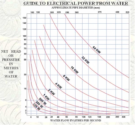
Power (watts) = Head (m) x Flow (litres/sec) x 9.81 (gravitational constant ‘g’) A typical water to wire efficiency is around 70%, so you should multiply the result by 0.7 to get the actual amount of electricity that you can expect from the site.
What I am thinking about is to substitute the moving water flow to one where a bucket of water moves along an incline to create the motion of flow. A sort of pulley and rope cable system on a pole that tilts towards the base of the incline for a good smooth ride.
https://www.builditsolar.com/Projects/H … fRiver.htm
Power = (1/2)(Turbine Efficiency) (Water Density) (Turbine Flow Area) (Water Velocity)^3
Normally the mass is what will cause the turbine to move so knowing the amount and time is a flow rate.
https://en.wikipedia.org/wiki/Stream_power
https://www.engineeringtoolbox.com/hydr … _1359.html
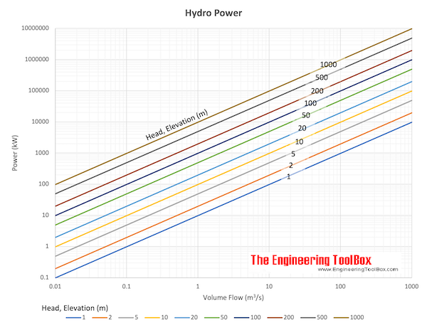
5 gallons is 0.01892706 meters cube
I see that we did wander into geothermal energy.
Offline
Like button can go here
#92 2022-09-11 15:11:43
- SpaceNut
- Administrator
- From: New Hampshire
- Registered: 2004-07-22
- Posts: 29,850
Re: Gravity Energy Storage
Rotation is required and that is torque.
Of course, when you need RPM's we are looking at that flow rate as it relates to the torque values.
https://www.studysmarter.us/explanation … al-motion/
https://en.wikipedia.org/wiki/Torque
Power in rotational systems (torque and frequency of a rotation)-527.png)
Offline
Like button can go here
#93 2022-09-13 21:57:47
- SpaceNut
- Administrator
- From: New Hampshire
- Registered: 2004-07-22
- Posts: 29,850
Re: Gravity Energy Storage
was thinking about how to fill the 5 gallon pale quickly and in a flush, it came to me in that a toilet tank is a quick exit of store water just waiting to go so since I need the water to fill the pale quickly that should work to do just that. Since I wanted to have multiple pales filling with separation it will then need adequate time to refill that toilet tank to be ready for its next use. The same mechanical float and valve can be used.
Depending on the count of fill ups I might need to build up a reserve area ahead to feed that tank from the well with a more powerful pump system since it's got to get to the height to enter into the generating systems pale for use.
Now to understand the time it would take to travel down the hill for the given distance.
Normally that is the water flowing into the turbine inlet pipe or in the water wheel.
https://www.calculatoratoz.com/en/flow- … calc-28554
https://www.waterprofessionals.com/lear … alculator/
V = 0.408 × Q/D2
V = Water Velocity; Q = Flow Rate; D = Pipe Diameter
https://www.askaprepper.com/homemade-wa … -generator
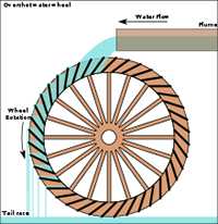
Usually, for a water wheel electric generator you need at least 3 feet of fall and at least 20 gallons per minute of flow. The more fall and flow you have, the more potential power you can generate. You can measure flow by building a weir in the creek and measuring how fast it will fill up a 5 gallon bucket.
Power Output in kilowatts-hour is calculated by the formula: KW = 0.004 x Q x V x H x C where:
Q = Weight of water (volume per sec x capacity of the buckets)
V = Velocity of the stream per second (meters)
H = Head, or height difference of water between the lip of the flume (head race) and the tailrace – meters
C = Efficiency Constant – usually around 50%This is how you can actually calculate the energy your water wheel electric generator will produce.
While the flow is the travel of the pale down the hill it's the same quantity used in just part of the rotation.
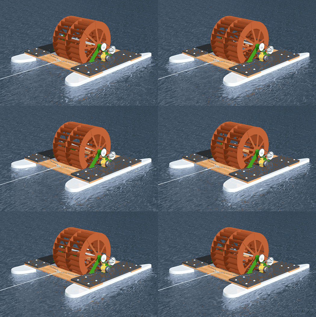
The 5-foot diameter water wheel shown can be scaled up or down. The surface speed of rivers varies between about 3-8 MPH. Floating water wheels are typically 25-45% efficient, however the pontoons shown are shaped like airfoils to increase the speed of the water between the pontoons under the wheel to increase the efficiency.
The water wheel turns at approximately 15-20 RPM. The water wheel can make use of a new style generator developed for small windmills that can operate as slow as 80 RPM. The required speed increase can be done first with a chain drive and then a belt-and-pulley system shown, or gearbox.
https://sites.google.com/site/denergysy … electrical

Offline
Like button can go here
#94 2022-09-18 17:29:45
- SpaceNut
- Administrator
- From: New Hampshire
- Registered: 2004-07-22
- Posts: 29,850
Re: Gravity Energy Storage
https://ee.usc.edu/stochastic-nets/docs … n-hill.pdf
full of calculus equations....not for me...
https://www.wired.com/2014/07/a-rolling … n-incline/
sliding

Rolling

Rolling Disk Using Torque
Offline
Like button can go here
#95 2022-09-23 18:31:13
- SpaceNut
- Administrator
- From: New Hampshire
- Registered: 2004-07-22
- Posts: 29,850
Re: Gravity Energy Storage
How much hydropower power could I generate from a hydro turbine?
maximum hydropower power output is entirely dependent on how much head and flow is available at the site, so a tiny micro-hydro system might produce just 2 kW, whereas a large utility-scale hydro system could easily produce hundreds of Megawatts (MW).
If you don’t mind equations the easiest way to explain how much power you could generate is to look at the equation for calculating hydropower:
P = m x g x Hnet x η
Where:P
power, measured in Watts (W).
m
mass flow rate in kg/s (numerically the same as the flow rate in litres/second because 1 litre of water weighs 1 kg)
g
the gravitational constant, which is 9.81m/s2
Hnet
the net head. This is the gross head physically measured at the site, less any head losses. To keep things simple head losses can be assumed to be 10%, so Hnet=Hgross x 0.9
η
the product of all of the component efficiencies, which are normally the turbine, drive system and generatorFor a typical small hydro system the turbine efficiency would be 85%, drive efficiency 95% and generator efficiency 93%,
https://dothemath.ucsd.edu/2011/12/how- … an-we-get/
Hydroelectric dams exploit storage of gravitational potential energy. A mass, m, raised a height, h against gravity, g = 10 m/s², is given a potential energy E = mgh. The result will be in Joules if the input is expressed in meters, kilograms, and seconds (MKS, or SI units). Water has a density of ρ = 1000 kg/m³, so if we know how many cubic meters of water flow through the dam each second (F), the power available to the dam will be P = ηρFgh. We have inserted η to represent the efficiency of the dam—usually around 90% (η≈0.90).
The height of the water behind the dam is the relevant height for the potential energy calculation, even if a given parcel of water is collected at the bottom of the dam. This is because the pressure of the water above provides the motive force. In the absence of turbines or other restrictions, the water would emerge from the penstock at a velocity of v = sqrt(2gh) so that a flow, F, would require an area A = F/v. For example, Hoover Dam, at 222 m high (in the days when Lake Mead was full!) would eject water at a stunning 67 m/s (150 m.p.h.) if a big hole opened up in the bottom. At the nominal flow rate of 1000 m³/s, this corresponds to a hole about 4 m in diameter
Some of the 10% inefficiency in hydroelectric dams is due to generator inefficiency, but some is because you can’t take all of the kinetic energy out of the water or it would stop flowing and stall the flow of the next batch. But nature is kind here, since kinetic energy goes as the square of the velocity. The velocity of the energy-sapped water is therefore sqrt(1 − η). So if we pull 96% of the energy out of the water, its flow velocity is 20% of the free-flow value (13 m/s in the foregoing example). Or we can grab 99% at a 10% exit speed (7 m/s, or 15 m.p.h.)
So there might be more fresh water if we use it for a more efficient power creation.
Offline
Like button can go here
#96 2022-09-23 19:49:20
- tahanson43206
- Moderator
- Registered: 2018-04-27
- Posts: 23,353
Re: Gravity Energy Storage
For SpaceNut re Post #95
The mathematics you posted inspired the thought of a kilometers deep geothermal bore hole that feeds water to an energy exchange system at the bottom of the column. A scenario that I've been thinking about was making steam out of the water and feeding that (or letting it feed itself) to the surface to operate a steam turbine on the surface.
However, the cold (condensed) water that returns to the shaft is being pulled by the Earth's gravity, so that there is a significant head built up at the bottom.
So! My question is... can the geothermal energy system provide electrical power at both the bottom of the shaft, as well as at the top?
(th)
Offline
Like button can go here
#97 2022-09-24 19:54:41
- SpaceNut
- Administrator
- From: New Hampshire
- Registered: 2004-07-22
- Posts: 29,850
Re: Gravity Energy Storage
The inlet water that ends up at the bottom could generate power from the fall, but you need to have the generator unit located some distance from that bottom.
Water that enters the chamber bottom needs to flash into steam to be able to rise to the top to power those generators before going back down the return pipeline so as to recycle it once more.
I would think that Calliban would be able to work those numbers.
Offline
Like button can go here
#98 2022-09-24 21:29:12
- tahanson43206
- Moderator
- Registered: 2018-04-27
- Posts: 23,353
Re: Gravity Energy Storage
For SpaceNut re #97
Thanks for considering the question about (possibly) harnessing the powerful head of water that would be available at the bottom of a 20 kilometer shaft.
Something to keep in mind is that the cold water turbine is going to be cooled by the cold water coming down the pipe.
That entire assembly would (I would think) be designed to accept cooling from the descending water, so that it would not matter how hot the Earth was around it.
The intention is to deliver the output of the cold water turbine to the steam generation facility (whatever ** that ** is).
I too am hoping this "opportunity" interests Calliban!
What I'm going for is a concept of drawing energy from the Earth sufficient to meet all power and heating requirements for the entire population, without using a bit of the remaining fossil fuel store provided by Ma Nature to give us a running start.
The question (that only someone like Calliban could answer) is whether the thermal energy store coming from the Core is sufficient to power the entire system, including descending cold water and steam driving up the pipe.
This is (as I understand it) a classic problem in managing thermal energy. It will require all the savvy that human engineers have acquired over recent centuries, to handle ** this ** situation efficiently and effectively.
I'd like to set a goal of 1 megawatt per Earth resident, so that the privation of so many is replaced with a modest standard of living for everyone, while the opportunity for those with talent and drive is unlimited.
(th)
Offline
Like button can go here
#99 2022-09-25 09:46:17
- SpaceNut
- Administrator
- From: New Hampshire
- Registered: 2004-07-22
- Posts: 29,850
Re: Gravity Energy Storage
Inlet cold is with a check valve at the bottom with a second steam pipe that goes to the generator. You would be looking at steam pressure to tell when to add more water.
Offline
Like button can go here
#100 2022-09-25 10:16:03
- tahanson43206
- Moderator
- Registered: 2018-04-27
- Posts: 23,353
Re: Gravity Energy Storage
For SpaceNut ... re this topic and post #99
This topic is about ** gravity ** energy storage.
Steam is covered in another topic.
What I've proposed is already covered by your previous posts in this topic.
If you imagine a water fall 20 kilometers long, you could imagine making a standard hydraulic dam power system, such as ones at Niagara Falls (and many other locations).
Steam is NOT involved, in any way, shape or form. ** This ** topic is about the down flow of cold water, as part of a gravity energy storage system.
What I have proposed (and am asking for confirmation) is a COLD WATER hydraulic water turbine-generator system, installed at the bottom of the geothermal pipe.
It doesn't matter that the environment around the generator is hot enough to make steam!
The water coming down the pipe is NOT steam. It is cold water from the surface that has been heated somewhat during descent, but is still well short of boiling temperature.
The water at the bottom of that pipe is going to have a nice head.
The calculations you showed us earlier in this topic ** should ** be able to show you how much energy you can collect from that column of water.
The water leaving the turbine will be collected by the heat exchange in the geothermal cavity under the pipe, and converted to steam, which will then travel up the pipe to the surface, where it will feed a second turbine able to operate with steam as the energy source.
I don't know if we have a topic dedicated to steam power production. The geothermal system under discussion here has ** both ** a gravity side and a steam side.
Thus, in a complete cycle, the same water molecules will deliver energy via cold water turbine, and later via a steam powered generator.
What we need is someone like Calliban to confirm that such a cycle is possible with known technology.
It seems to me that this is a thermal engine, which is energized by fission that occurs in the center of the Earth.
(th)
Offline
Like button can go here

