New Mars Forums
You are not logged in.
- Topics: Active | Unanswered
Announcement
#176 2020-06-02 13:55:12
- tahanson43206
- Moderator
- Registered: 2018-04-27
- Posts: 23,652
Re: 3D Printers
This is a followup to Post #136
For anyone interested in seeing what the opening section of Chapter 1 ** should ** look like, the video is a good introduction.
Edit 2019/11/19 ... Apparently my system is too old to run properly with Fusion 360. It reported a problem with the graphics card, and the manufacturer of the graphics card shows it as a legacy product. The drivers on offer are even older than the Windows 10 drivers in use now. Fortunately, the system works fine with Blender and everything else I need to run on this system, but it is disappointing to have to face the fact that the world has moved on a bit since this system was new.
If anyone else tries Fusion 360, I'll be interested in your experience.
Edit: 2019/11/21 A newer notebook apparently has a graphics chip that is new enough to run Fusion 360 correctly.
I'm planning to resume a step-by-step report based upon Lydia Cline's book.
(th)
I was able to budget for a new graphics card for the Windows 10 desktop where I wanted to run Fusion 360.
The laptop was too underpowered for the software, although the Graphics processor was just barely adequate.
Fusion 360 is now running with fair performance on the desktop.
I pulled one of the Blender models into Fusion 360, and it didn't complain.
Meanwhile, Shapeways.com refuses to accept the model. I accept their judgement as reasonable, because they have to actually ** make ** the object.
I think what Shapeways inspection software is complaining about is the presence of unneeded artifacts left over from the convoluted train of boolean logic I used to create the model. For a scene in a movie, dangling vectors are unimportant, but for a 3D printer, their presence is unwanted.
Fusion 360 is part of the Autodesk family of applications for ** real ** world product development.
Even though (I understand) Fusion 360 is a subset of the capabilities a professional would be using, it is still close to overwhelming for me.
(th)
Offline
Like button can go here
#177 2020-06-04 09:48:59
- tahanson43206
- Moderator
- Registered: 2018-04-27
- Posts: 23,652
Re: 3D Printers
For Louis re topic ...
In looking back at the first post in this topic, I get the impression you were observing the scene, and did not have a goal or objective in mind.
I'd like to offer you the opportunity to consider changing the scope of the topic by going back to the first post and adding some text to give future readers who will be stopping by the forum a sense of where the topic was heading in 2020.
I understand that no one else currently contributing to the forum has a 3D Printer, or 3D Printer design software (or admits to either).
However ** that ** could change in an instant, if someone with an interest in 3D Printing were to stop by the forum, touch this topic, and find something going on that is of interest with respect to the ambition to settle Mars.
I have a distinct advantage over others who are currently exploring 3D printing as a practical art ... I am ** just ** far enough along in the learning process to be able to make simple objects, but ** not ** so far along as to qualify as an expert for whom teaching novices is an unwelcome distraction.
In that light, I would like to report a stage in discovery that eventually would occur to anyone. It ** has ** occurred to others, because Google provides numerous citations of folks expressing frustration at the (to them) surprising behavior of boolean logic. I just learned yesterday that the behavior I had observed in Blender is NOT unique to Blender. It is (apparently) well documented as an unwanted side effect for designers using Fusion 360 (a free Autodesk package).
I found a lengthy passage in a chapter on modifiers in "Fusion 360 for Makers" explaining how the process of boolean operations on models causes confusion due to failure of the designer to anticipate the results that will inevitably occur when two hollow shapes are combined with the union boolean command.
To summarize (as well as I can), the problem that arises occurs because parts of the combined shapes become part of the interior of the objects with which they are joined. I see this result indirectly, when Shapeways software complains that I have uploaded an unprintable object.
Edit#1: The experienced reader will be aware that slicing packages (such as Slic3r, Cura and Microsoft's 3D Print for Windows 10) can show the interior of objects, and thus the artifacts introduced by uninformed boolean logic operations. However, until this moment, I did not realize the significance of the displays I've been seeing from these tools. I ** finally ** saw the light (in a manner of speaking) when the author Lydia Sloan Cline got across to me that objects are supposed to be ** empty ** when submitted for 3D printing. I've been sending objects with untold numbers of hanging vertices and faces, and (apparently) the slicer software has been cleaning up for me all this time. Shapeways has finally thrown in the towel, forcing me to mend my ways.
There are (apparently) a number of commands added to both Blender and Fusion 360 to clean up artifacts created in objects due to boolean operations.
However, in experimenting with these, I have not yet achieved anything close to mastery of this aspect of design.
The approach I'm thinking of starting now (for the umpteenth restart) is to design shapes that are hollow to begin with, and which do NOT intrude into the shapes to which they are to be bonded.
Edit#2 ... I found that cleaning thoroughly between boolean operations (ie, doubles and loose elements) seemed to resolve problems so that worrying about the interiors of the objects was not necessary. However, after adding three of the planned four corner cubes to the Blender model for CushionGuide, I found that for some reason, the system refused to allow me to add the fourth corner. I'm investigating solutions as of 2020/06/06.
SearchTerm:3DPrint
SearchTerm:BooleanArtifacts
SearchTerm:3DDesignToAvoidArtifacts
Edit#1:
SearchTerm:3DDesignBestPractice
This is an update based upon a series of boolean updates on the CushionGuide part.
I started over with the basic cushion complete, but before addition of the corner fixtures. I performed boolean logic cleanup after every action.
I ** also ** decided to try renaming the part to be combined with the UNION command, although I don't know if that was necessary. What I ** do ** know for sure, is that after each boolean logic operation, the clean-up commands found vertices or faces to remove.
The only two cleanup commands (in Blender) that seemed to work consistently were "doubles" and "loose". It's possible the additional commands might work, but I didn't see any effect of clicking on them, and indeed, I may not understand how to use them.
In any case, using the simple cleanup procedure has allowed progress so that three of the four corner fixtures are installed. Only one remains to be installed, and the basic form of the Cushion Guide will be complete. After that, only a bit of touchup is needed:
1) Add holes through the corner fixtures (to hold Tether structures such as guide rails)
2) Bevel the corners and edges
(th)
Last edited by tahanson43206 (2020-06-06 06:53:33)
Offline
Like button can go here
#178 2020-06-04 12:33:30
- tahanson43206
- Moderator
- Registered: 2018-04-27
- Posts: 23,652
Re: 3D Printers
As a follow up to #177
OpenSCAD was recommended by the leader of (one of several) local 3D Printer groups. I've held off until now, because it runs using scripts, and does not have a GUI interactive interface as does Blender or Fusion 360.
However, there is some appeal to the idea of working at the level of coding, because there may be an advantage in achieving control of the generated output.
In any case, for the future reader of the forum who may want to carry out 3D printing activities, here is the opening section of the OpenSCAD Help page:
OpenSCAD
The Programmers Solid 3D CAD ModellerOpenSCAD Tutorial
Table of Contents
Chapter 1: A few words about OpenSCAD and getting started with the first object
Chapter 2: Scaling the model and first steps for parameterizing models
Chapter 3: Resizing models and more ways of combining objects
Chapter 4: Introducing modules to organize the code
Chapter 5: Using multiple scripts and libraries
Chapter 6: Control flow, conditional creation of objects
Chapter 7: Loops and creating more complex patterns
Chapter 8: Extruding 2D shapes into 3D objects
Chapter 9: Math, calculations and low level geometry creationOpenSCAD User Manual
Table of Contents
Introduction
First Steps
User Interface
Input Devices
Customizer
Import and Export
Commented Example Projects
Paths
Using an external Editor with OpenSCAD
Using OpenSCAD in a command line environment
Building OpenSCAD from Sources
FAQ
Libraries
Tips and Tricks
GlossaryOpenSCAD Language Reference
Table of Contents
The OpenSCAD Language - General
3D Objects, Projection
2D Objects, Primitives, Text, Extrusion to 3D
Transformations
Boolean operations
Conditional and iterator functions
Mathematical operators
Mathematical functions
String functions
Type test functions
List comprehensions
Other language features
User defined functions and modules
Debugging aids - modifier characters
Importing geometry, Exporting geometry
(th)
Offline
Like button can go here
#179 2020-06-06 12:44:57
- knightdepaix
- Member
- Registered: 2014-07-07
- Posts: 239
Re: 3D Printers
Do you mean using 3D printers and lunar regolith to print a building?
Offline
Like button can go here
#180 2020-06-06 17:35:49
- tahanson43206
- Moderator
- Registered: 2018-04-27
- Posts: 23,652
Re: 3D Printers
For knightdepaix re Post #179
Please refer to the post to which you have addressed your question or comment,by including the number of the post in your contribution to the topic.
The manager of this topic is Louis. However, anyone can contribute to the topic, which has by now accumulated 180 posts.
(th)
Offline
Like button can go here
#181 2020-06-07 20:49:52
- tahanson43206
- Moderator
- Registered: 2018-04-27
- Posts: 23,652
Re: 3D Printers
For Louis ... as manager of this topic, you would be justified in asking why a screen video recorder would be pertinent to 3D printing.
The answer is (a) Help Desk assistance, and (potentially) (b) Instructional material for students or (perhaps) an audience.
In the present instance, I am attempting to understand Fusion 360, which is a free Autodesk package for 3D Printer or computer controlled machine design. I am attempting to make the transition from Blender to Fusion 360, and have run into a problem with the simplest thing imaginable. I want to simply punch a hole in the CushionGuide which was assembled by Blender. However, for reasons which are not apparent to me, after importing the design to the Fusion 360 workspace, and calling up the Hole Punch feature, I cannot select the CushionGuide. I can select the CushionGuide just fine BEFORE I activate the hole punch feature, but the instant I do that the CushionGuide deselects, and nothing I do after that allows for selection. There are a number of YouTube videos about this exact problem, but I did not succeed with any of them.
Fortunately, Autodesk provides a free video recorder, so I just installed it, and will give it a try tomorrow. In reviewing the Help Desk responses, I noticed that the representatives asked the customer to submit a screen recording. After a few seconds of playback, the representatives usually say something like "Ah ha!" and explain the solution. In one notable case, the representative said ... "Yup! That's a bug! Thanks! Here's a work-around while we fix it".
Here are a few lines from the opening screen, in case anyone else in the forum readership has a similar need:
Not Your Average Screen Recorder
Keystrokes
Tracks your keystrokes and shows them in the video.Mouse movement and clicks
Displays mouse movement and mouse button clicks in a large, easy-to-follow graphic.Commands on the timeline
Captures your commands and actions on the timeline as you are recording.
Some of the features listed above are ** very ** desirable, and I wish they'd been available (or I'd know about them) earlier.
(th)
Last edited by tahanson43206 (2020-06-07 20:53:17)
Offline
Like button can go here
#182 2020-06-08 07:04:59
- louis
- Member
- From: UK
- Registered: 2008-03-24
- Posts: 7,208
Re: 3D Printers
Good luck TA!
Here's an interesting video on AI Space Factory's 3D printed habs.
They are building for both Mars and Earth.
For Mars, the process will be slow, however.
Let's Go to Mars...Google on: Fast Track to Mars blogspot.com
Offline
Like button can go here
#183 2020-06-08 07:41:41
- tahanson43206
- Moderator
- Registered: 2018-04-27
- Posts: 23,652
Re: 3D Printers
For Louis re #182
Thank you for your encouragement! I'm hoping to have something to report in a day or so.
In the meantime, thank you for the link to the interview with the developer of the Mars cone house idea. I appreciated the explanation for the design value of strength of the structure with respect to the internal forces it must bear.
I am picking up on your observation that the process is slow ... I would like to point out that the stage of development the video shows us is ** very ** early. There is NO reason (that I can think of) why there could not be a minimum of four extruders at work simultaneously, and perhaps more will eventually be given a chance to add material to the form simultaneously.
There are two ways this could be accomplished ... the form can be rotated, but that is more practical for a manufacturing facility indoors where the objects to be manufactured are smaller.
However, for a field construction operation, the machines can be mounted on a circular track and caused to advance along the track while the extruder does its work. The machine shown in the video is able to stretch to the far side of the build out of necessity, but a multiple extruder configuration would be designed to only stretch to the center (or to the point in the build which is closest to the center).
Finally .... slow compared to what ?
I expect that construction using traditional concrete forms will be slow on Mars. It is certainly slow on Earth, compared to a speeding train.
(th)
Offline
Like button can go here
#184 2020-06-08 09:13:36
- louis
- Member
- From: UK
- Registered: 2008-03-24
- Posts: 7,208
Re: 3D Printers
Well slow in two senses: in comparison with building the same structure on Earth (he indicated 200 hours to build on Earth - maybe about 2 weeks - but "months" on Mars) and I would say in comparison with building the same volume with a cut and cover technique or a number of other techniques. I couldn't really fathom why he was asserting it would take "months". It might be he was talking about building the first one, in which case, yes, you would have to source and mix the building material before you could extrude!
One thing I would mention, which I have proposed before is that the build could take place within a construction hab - a large volume inflatable space maybe operating at 20% of Earth air pressure with a suitable mix, allowing humans to move freely using breathing apparatus. The hab could be kept at a constant temperature and artificially lit, allowing for 24.6/7 working if necessary.
For Louis re #182
Thank you for your encouragement! I'm hoping to have something to report in a day or so.
In the meantime, thank you for the link to the interview with the developer of the Mars cone house idea. I appreciated the explanation for the design value of strength of the structure with respect to the internal forces it must bear.
I am picking up on your observation that the process is slow ... I would like to point out that the stage of development the video shows us is ** very ** early. There is NO reason (that I can think of) why there could not be a minimum of four extruders at work simultaneously, and perhaps more will eventually be given a chance to add material to the form simultaneously.
There are two ways this could be accomplished ... the form can be rotated, but that is more practical for a manufacturing facility indoors where the objects to be manufactured are smaller.
However, for a field construction operation, the machines can be mounted on a circular track and caused to advance along the track while the extruder does its work. The machine shown in the video is able to stretch to the far side of the build out of necessity, but a multiple extruder configuration would be designed to only stretch to the center (or to the point in the build which is closest to the center).
Finally .... slow compared to what ?
I expect that construction using traditional concrete forms will be slow on Mars. It is certainly slow on Earth, compared to a speeding train.
(th)
Let's Go to Mars...Google on: Fast Track to Mars blogspot.com
Offline
Like button can go here
#185 2020-06-08 11:39:49
- tahanson43206
- Moderator
- Registered: 2018-04-27
- Posts: 23,652
Re: 3D Printers
For Louis re topic and specifically Post #184
I recall your sensible suggestion to build 3D structures (or any structures) inside enclosure, and agree that it seems to make a lot of sense, since grit in the atmosphere is just ** one ** annoying intrusion on what would appear to be a high-precision process.
However, I'm logging in right now to (try) to report an update on the Fusion 360 package, and my attempt to use it to punch a hole in a 3D model created in Blender.
https://knowledge.autodesk.com/communit … 2a619a310d
I have no idea if the link above will work, but if it ** does ** work, it shows the problem I am confronting.
In asking Autodesk for help, I learned (quickly enough) that since I am a free-trial user, I'm not eligible for company support. However, there appears to be a vibrant user community, with active support by Autodesk employees (or by experts who are willing to donate their time to help with issues.)
I submitted a post explaining the problem and hope that someone will take a look at it.
OK! The link played for me, so hopefully it will play for others.
Since there is no audio with the recording, I'll provide a quick summary of the flow:
1) Open file from saved collection in Fusion 360 online repository
2) View the model from several perspectives so the help desk person can visualize it
3) Show that normal selection works (the model turns blue after selection)
4) Open the hole tool. Note that the model deselects immediately
5) Move the hole tool window to the left
6) Select the single hole option
7) Click the "Select" button (no effect)
8) Attempt to select the body as before (no effect)
9) Attempt to use the "brush" select feature (no effect)
(th)
Edit#1: This was quick! I'll try the suggestion later today.
Hi tahanson,
guenther.andresen (Mentor) posted a new reply in Fusion 360 Support on 06-08-2020 10:30 AM .
Re: Unable to select imported body after starting hole feature
Hi,
did you convert the STL to BREP? > needed!
günther
Reply | Accept as solution | Like this post
(th)
Last edited by tahanson43206 (2020-06-08 12:38:56)
Offline
Like button can go here
#186 2020-06-08 16:27:35
- SpaceNut
- Administrator
- From: New Hampshire
- Registered: 2004-07-22
- Posts: 30,051
Re: 3D Printers
This floating 3D-printable tiny home is designed to last 100 years
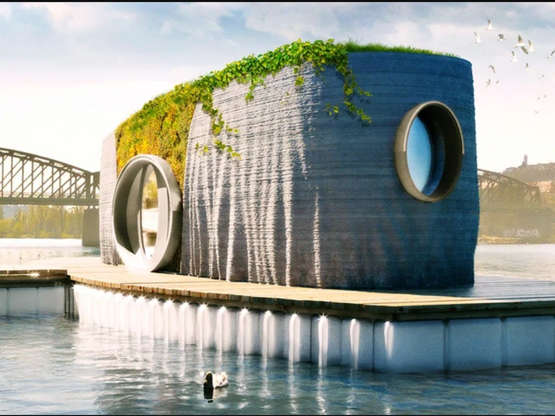
It looks like layered concrete...with fiber with in it for shaping structures.
The structure will be built in only 48 hours, and can save up to 50% of the building costs of conventional buildings, its proponents say. Using 3D printing technology, the house can be built about seven times faster than using traditional methods. It can print about six inches per second, for 48 hours total to construct the 463-square-foot home.
Another reason for it to be built within a controlled environment
After 28 days, the concrete hardens completely to the equivalent of a typical bridge.
Something for mars that is a bonus is
3D printing also eliminates at least 20% of carbon dioxide emissions from traditional construction, which accounts for nearly half of total emissions in the country.
Offline
Like button can go here
#187 2020-06-09 06:41:16
- tahanson43206
- Moderator
- Registered: 2018-04-27
- Posts: 23,652
Re: 3D Printers
For SpaceNut re #186
A much needed and practical application of this technology is housing for the billions of humans who are at risk due to global warming. Much of the Asian world already has habitation build as floating housing on water. In a location such as Bangladesh, which is so close in elevation to the sea even today, this housing concept could prove helpful. On aspect of the situation I was unable to determine is how flows of materials into and out of the structure are handled. Existing practice in mooring facilities for sailing craft are probably a good model. An architect planning for Bangladesh would (probably) need to assume nothing is available from the existing location, and design everything needed to sustain a community based upon these devices.
It's good to see innovation like this coming from: Czech Republic
(th)
Offline
Like button can go here
#188 2020-06-13 12:25:54
- tahanson43206
- Moderator
- Registered: 2018-04-27
- Posts: 23,652
Re: 3D Printers
For Louis .... here is a candidate for the ultimate 3D printer ... If I understand the video correctly, the research team has found a way to position individual carbon atoms in a lattice using two laser beams.
This Photon-Printed Carbon Is Stronger Than Diamond
This is a video rather than text. I'd be interested in seeing a text report on this research if someone finds one.
(th)
Offline
Like button can go here
#189 2020-06-16 07:15:35
- tahanson43206
- Moderator
- Registered: 2018-04-27
- Posts: 23,652
Re: 3D Printers
For Louis re Topic ...
There has been an active discussion on NewMars forum in recent days/sols, regarding the possibility of making a rocket launch from Mars or the Moon, using non-liquefied fuel and oxidizer. While those topics appear likely to arrive at a null conclusion, they HAVE generated a vigorous flow of ideas about how pressure might be contained on Mars or the Moon.
Overnight, it came to me that work already done (on Earth of course) to develop large scale 3D printers fits nicely into a Mars scenario which requires large scale pressure vessels. The size I have in mind is 30 meters diameter rings, which would be bolted together in cylinders of arbitrary length, to make pressure vessels suitable for Mars, the Moon, or just about anywhere, including the Earth.
It is possible for anyone with 3D Printer design tools loaded onto their computer to work on this project, and I invite any forum reader who is not yet registered in the forum to apply for membership and participate. Eleven spammers applied for membership yesterday, so we know the registration system is working just fine.
The 3D project I would like to offer for your participation is to design a ring that is 30 meters in diameter, of which 1 meter is allocated to the material of the ring itself. The ring, therefore, would be 1/2 meter in horizontal thickness (X and Y). The vertical thickness would be determined by factors at the build site, and by the preferences of the Construction Contractor who is directing the onsite build. To start things off I'll suggest a thickness (Z dimension) of 1/2 meter.
For those with a background in chemistry, there is the opportunity to design suitable extrudable material for each environment where pressure vessels are needed. To the best of my knowledge at this moment, EVERY solar system body where humans could imagine living at all, would be a candidate for construction using this method.
For both Mars and the Moon, the distinct advantage of the ring concept offered here is the ability to withstand both internal bursting pressure (from gases introduced into the volume after leaks are sealed) and external loads imposed by loose regolith piled on top of the structure to improve protection from radiation and flying objects of modest size.
I intend to work on this concept at some point, but am currently working on the CushionGuide for the Phobos tether under discussion in another topic.
A detail for someone to work out is how to space holes for fasteners. I am imagining bolts made of suitable material spaced every so many degrees around the ring circumference, to facilitate tight bonding of the rings as they are added to achieve the longitudinal objective of a particular contract.
End caps are another detail to be worked out. One of these could be closed, but at least one of them should be fitted with fittings to permit gas to be admitted to the facility or drawn from it, if storage is the purpose, or openings if people or other larger objects are to be admitted to the facility.
If there is interest, this could turn into a topic of its own. For now, I'd like to invited current or prospective members to post work here in Louis' topic.
For new members of the forum, I'd like to remind you that you can show your work on the forum using links to imgur.com. You instruct your 3D package to make an image, upload that image to imgur.com, right click on the image at imgur.com, and select the link provided by imgur.com for BBCODE sites, of which this forum is one. Paste that link into your report of progress.
(th)
Last edited by tahanson43206 (2020-06-16 07:19:52)
Offline
Like button can go here
#190 2020-06-19 04:38:18
- elderflower
- Member
- Registered: 2016-06-19
- Posts: 1,262
Re: 3D Printers
30 metre diameter might be a little bit ambitious. It isn't difficult to design a tank with a membrane wall that would withstand considerable internal pressure even at 30 metres diameter (100ft for the unreconstructed oldies). It is the external pressure of the regolith and the tanks weight supports that are difficult. Submarines are designed to withstand external pressure and they don't have membrane shells. Likewise LPG storage bullets are designed to be mounded, but I have never seen one that size.
Offline
Like button can go here
#191 2020-06-19 05:12:16
- tahanson43206
- Moderator
- Registered: 2018-04-27
- Posts: 23,652
Re: 3D Printers
For elderflower re #190
Thank you for your support of this initiative within the 3D Printer topic.
The idea of placing a membrane of some kind within a pressure vessel made of 3D printed rings is interesting. It would address the concern of dealing with leaks, which would naturally occur at the seams between the rings.
The rings themselves, of course, would be made of regolith.
The challenge for chemists in the membership is to think of a mixture that might be made of Mars (or Lunar) regolith, suitable for the rock-like ring shape envisioned for this application.
There are images available that show something like what i am talking about, and I'm pretty sure there is one in this topic.
However, I was not able to find it in the time I have available this morning. What the image showed was a large extruder laying thick beads of concrete-like material in rings. The rings were stacked on top of each other to make an oblate (or think egg shaped) structure that was offered for consideration for Mars, and even for Earth for one-family homes.
OK... the images are over in the Human missions topic ... here's one: http://newmars.com/forums/search.php?se … =800920179
What I'm talking about here is a construction element that would NOT be stacked vertically, as shown in the Mars competition example, but instead would be bolted together horizontally, for as great a distance as is needed for a particular application.
Unlike with the example shown in the Mars habitat competition, the 3D Printer need not necessarily be located at the job site. The rings could be fabricated elsewhere and transported to the build site. They would be rotated to a vertical position, and bolted to each other to make a cylinder of the required length.
Thus, your suggestion of a membrane to line the inside walls of the structure is helpful.
The material chosen could have immediate psychological benefit as well as the practical value of keeping gas molecules inside the structure. The colors and even the texture of the material could be chosen to provide agreeable interiors of the structures, depending upon the purpose for which they are constructed.
On Earth, the traditional way of coating the interior of a living space is a coat of paint, or perhaps some wall paper, but the need for sealing against leaks makes the value of a membrane chosen for the purpose to be much greater.
Edit#1: And thank you for the suggestion to consider smaller diameter rings. 30 meters was offered to start the subtopic.
Since the structure is intended to be laid out horizontally, I would expect there would be a floor constructed at the mid-point, so that living space would be within the upper half cylinder, and storage and utilities would be below. This is somewhat similar to the design of ocean going vessels.
(th)
Last edited by tahanson43206 (2020-06-19 05:16:06)
Offline
Like button can go here
#192 2020-06-19 06:50:34
- tahanson43206
- Moderator
- Registered: 2018-04-27
- Posts: 23,652
Re: 3D Printers
The contribution by elderflower in Post #190 led to a suggestion in the closing of post #191 about similarity between a cylinder made of regolith 3D printed rings and an ocean going vessel inspires this follow up for Earth.
Several locations on Earth are subject to challenges caused by natural forces. I'm thinking of hurricanes, tornadoes, earthquakes and lesser disturbances such as severe storms that deliver golf ball or even softball sized hail on occasion.
The vision of a 3D printed bolted ring cylinder for Mars might find application here or there on Earth.
The situation of millions of folks who live in locations such as Bangladesh comes to mind, as just one example, although the United States has numerous regions which are subject to severe flooding.
The example from Nature that seems most applicable here is the snail, which carries a sturdy (relatively speaking of course) "house" around with it.
On Mars, I would expect a habitat constructed of bolted rings would not open to the natural environment, since that environment is hostile.
However, on Earth, such a habitat could be constructed so the home for humans would slide in and out of the structure. In time of emergency, the home would slide back into the cylinder, the "door" would be pulled up, and the habitat could then protect the occupants against most disturbances.
Such a structure would need to be water tight, so the membrane elderflower suggested might be better applied outside, so the structure could float if necessary.
On Earth, such rings might be conveniently fashioned of concrete, or if a local variation of a material that will harden to a concrete-like state is available, then it might be chosen.
Homes in tornado vulnerable regions of the United States might find protection in shelters such as this worth the investment.
Edit#1: Homes in fire prone regions are in a different category. For ** those ** the liner would seem best placed ** inside **, where internal pressure can be applied to keep external gases out while the protected family watches TV reruns inside.
There would seem (to me at least) to be a substantial potential market for protection systems along these lines, in every part of Earth.
(th)
Last edited by tahanson43206 (2020-06-19 07:50:05)
Offline
Like button can go here
#193 2020-06-19 16:44:15
- SpaceNut
- Administrator
- From: New Hampshire
- Registered: 2004-07-22
- Posts: 30,051
Re: 3D Printers
The one two punch of katrina and rita (topics burried in free chat) holds images of quick construction habitat units. Some are prefab erect and nail together kits to tow it in structures of course small as all you want initially is to get out of the weather conditions to be able to bring back a shade of normalcy to life.
Offline
Like button can go here
#194 2020-06-20 04:01:05
- elderflower
- Member
- Registered: 2016-06-19
- Posts: 1,262
Re: 3D Printers
Concrete, especially steel reinforced concrete, is brilliant stuff in compression. Not so good in tension! If you want to make up rings to support external loads such as an overburden of regolith, you are essentially talking about tunnel liner sections. If you then want to pressurize your tunnel/ concrete sectional hab, you will need a pressure rated membrane inside it. This will be elastic material such as Aluminium alloy, Stainless steel, GRP etc which will expand under pressure- even just a little bit so it cannot be applied directly to the concrete sections. Additionally it will need to be insulated to prevent heat loss to the surrounding ground and possible destabilisation due to migration of ice away from the warmth. This means that your stainless or aluminium liner becomes almost an independent structure attached to the concrete by flexible supports to preserve the insulation and to allow expansion. If you use GRP that isn't quite such an issue as it isn't very stiff, so can be deformed quite readily and the supports can be more solid.
Offline
Like button can go here
#195 2020-06-20 06:18:53
- tahanson43206
- Moderator
- Registered: 2018-04-27
- Posts: 23,652
Re: 3D Printers
For elderflower re #194
Thank you for adding your insight to this topic! May I (try to) invite your consideration of a scenario which follows from the explanation you have provided. I understand (at least the gist) of your advice to plan to line the interior of a ring with a suitable liner material. I am thinking primarily (in the present series) about the manufacturing process.
In other words, I am trying to imagine how to build the walls of a cylinder in ring shaped sections, which can be manufactured some distance from the job site and transported to the job site where they would be bolted together to make a strong structure, suitable for various purposes, on Mars, the Moon, or on Earth.
In an earlier post, I have proposed use of a 3D Printer (designed for the purpose) to manufacture rings of chemically bound material made from regolith available at the build site. Because that material will depend upon the circumstances, it is a bit challenging to make general predictions, but it does seem reasonable to imagine the material will be prepared for extrusion from a nozzle, and that chemical processes will occur to provide strength and resiliency appropriate to the environment.
Now to your advice ... Can you imagine adding a layer of (something) to the interior of the ring, suitable for forming the kind of vapor lining needed, with the feature that the material (whatever it is) will bond to the matching layer on the already-installed ring.
In traditional human practice (as I understand it) the concrete lining (of a tunnel for example) is poured into forms which are set for the purpose, and then removed after the concrete has solidified. If an additional layer of material is needed, it is then applied in a separate process, such as brushing or rolling.
In the scenario I am trying to imagine, the ring and its lining would be assembled separately from the job site, and then transported to the job site to be bolted onto the existing structure.
Can you imagine a material (and installation procedure) that would allow the gas tight layer to be installed at the same time as the load bearing outer ring?
(th)
Offline
Like button can go here
#196 2020-06-21 09:10:15
- elderflower
- Member
- Registered: 2016-06-19
- Posts: 1,262
Re: 3D Printers
T A Hanson. Some thoughts about underground habs.
Spray concrete reinforced with stainless whiskers or maybe asbestos fibres is probably one answer but it lacks the true circularity of a sectional concrete liner and the fibres are not aligned and therefore it cant be loaded to the same degree. Consequently it uses more material for the same duty than the precast sectional liners commonly used, which will efficiently support very large loads, even though the spaces between the rings and the tunnel walls must be filled with grout. Note that the grout is not reinforced. At Mars temperatures thick steel sections will be embrittled and may fracture so large steels should not be relied on unless specifically formulated for extreme low temperatures. Note that 300 series stainless does not suffer from this. Neither do 6% and 9% Nickel steel, which are popular for LNG tanks (where corrosion is not an issue, so stainless is not needed). 3% Nickel is also resistant but when welded it's resistance can fail.
It is the requirement for insulation which prevents you from using bare concrete for your hab. It could be used as is if you don't mind extreme cold and a vacuum but that doesn't suit everybody. You can spray insulation quite easily and I suppose a formulation for that spray process could be made to work in a near vacuum. It may need temporary heating of the surface to enable it to stick but that would be OK for short duration. Alternatively insulation could be made up off site and installed in sections. Insulation tends to be light weight but quite weak so separate supports must be provided for the liner. There is an exception to this which applies when the insulation is a completely evacuated powder or fine particles. You will be used to powders like graphite or talc which are quite fluid, but their fluidity is due to the layer of gas adsorbed onto each particle, which lubricates them. In a good vacuum the particles become immobile and the insulation can then support quite large loads. I doubt that the 11 mBars at Mars is sufficiently low for this immobilisation to occur.
When you have insulation it must be prevented from getting damp as this severely impacts its effectiveness so you must provide a barrier on the warm side to keep moisture vapour from getting into the insulation. At some point on the temperature gradient in the insulation, moisture would fall to its dew point and from there onwards your insulation layer would become wet, reducing the effectiveness. In really cold conditions it freezes and becomes a moderately good conductor of heat and quite rigid (remember the frozen foam insulation that resulted in the loss of a shuttle). This process occurs with anything that will condense at or above the temperature of the cold side of the insulation layer, so cryogenic insulation is always evacuated, either as a Dewar vessel or as particulate insulation. Otherwise any gases would be liquified in the layer.
The condensation issue is one reason you need a liner membrane. The other is to take wear and tear and transmit loads from the activities inside the hab/tunnel. The supports have to carry those loads to the concrete casing without also carrying too much heat. They must also carry the self weight of the liner and allow for differential expansion between liner and tunnel.
Since Mars has quakes you will have to design for dynamic loads, and since you don't know much about the ground conditions, you will have to allow for some subsidence. Your design will need to be fault tolerant, which means sectionalising it to allow a fault in one zone to occur without jeopardising the entire structure.
My conclusion would be that it will be a long time before we can design a secure bored tunnel hab
A cut and cover design would be somewhat easier and could be fabricated offsite either whole or in sections from a material like GRP sandwich, but this would limit the depth of burial. Such a structure can be laid down on a sand bed and be inherently flexible so unlikely to fail in modest quakes or subsidence and would be my favoured solution. The issue of condensation doesn't arise because the insulation is entirely encapsulated in GRP. Fibres might be basalt and resins might be made from CO2, Nitrogen and water, not easy but possible given sufficient power and a chemical plant.
Offline
Like button can go here
#197 2020-06-21 09:52:13
- tahanson43206
- Moderator
- Registered: 2018-04-27
- Posts: 23,652
Re: 3D Printers
For elderflower re #196
Thank you for this generous addition to the 3D Printer topic!
In order to find it easily in future I'm going to set a couple of bookmarks, as I have done in the past with posts by GW Johnson and kbd512 and others.
SearchTerm:UndergroundHabitats
SearchTerm:elderflowerOnRingDesign
It will take several readings before I feel I understand the material well enough to ask the next question.
My goal here is to try to assemble as much knowledge and insight as possible, to (hopefully) benefit those who will be dealing with these issues on the ground in coming decades.
However, at the same time, I'd like to point out to anyone who chances upon this post or the topic of which it is a part ... many ideas being considered for the extreme conditions of Mars are likely to have value in planning for extreme environments on Earth.
For SpaceNut .... I'd like to invite you to think about the place of the entire field of Architecture in the NewMars Index structure.
It might take a while for Architecture to earn its own place on the top level of the Index, so I'm hoping this post will help to get the process started.
I would nominate the present focus of the 3D Printer topic as an example of a topic that would fit well into an Architecture Index level category.
The topic (were it to come to pass) might have a title like: Ring Structure for Cylindrical Habitat Design
The topic, were it to come to pass) could/should then include all the chemistry, physicals, engineering and (of course) architectural considerations that must be taken into account when building.
In elderflower's post just above, a variety of environmental concerns are listed. Each of these must be addressed in a design where humans will take up residence, or where valuable materials are to be stored.
(th)
Offline
Like button can go here
#198 2020-06-28 15:15:13
- tahanson43206
- Moderator
- Registered: 2018-04-27
- Posts: 23,652
Re: 3D Printers
This is a follow up to post #185 about 3D Print design using Fusion 360 on a Windows 10 machine
The very same day as a reply was received offering a way forward, the Windows 10 machine stopped running Fusion 360.
I suspect interference between Fusion 360 and the tool downloaded to record the problem, which is also made by Autodesk.
It has taken since that day for me to locate an old Windows 7 removable hard drive copy, update it to as of the closing of Windows 7 in January of 2020, and confirm that Fusion 360 runs.
This evening, I completed the first step of the recommended procedure, which was to convert the stl file from Blender to BRep, which is (apparently) the native mode used by Fusion 360 for solid models.
The conversion appeared to go smoothly this evening. At least no errors were generated.
I'll attempt to punch holes in the CushionGuide tomorrow.
http://newmars.com/forums/viewtopic.php … 10#p168910
(th)
Last edited by tahanson43206 (2020-06-28 15:15:41)
Offline
Like button can go here
#199 2020-07-01 09:45:22
- tahanson43206
- Moderator
- Registered: 2018-04-27
- Posts: 23,652
Re: 3D Printers
As a follow up to #198 ...
Thanks to Fusion 360 persisting on my restored/updated Windows 7, and to the helpful advice of two community members on the Fusion 360 forum, I punched my first hole in the CushionGuide body imported from Blender. The required step was to convert from stl (from Blender) into BRep (native solid mode in Fusion 360). Suddenly the "hole punch" subroutine started working.
As a side note which may be of interest to someone who chances upon this topic and is thinking of trying Fusion 360 (free for 1 year), the Inspect>>Measure tool is ** very ** helpful.
Here is an image (if I can get it to work) of the top of the CushionGuide with an experimental hole punched:

Next on the agenda is to study the hole punch feature to learn how to set the location of the punch precisely. The default is to follow the mouse and then align to the nearest snap point.
Edit#1: For reference, this work is inspired by the topic of this post:
http://newmars.com/forums/viewtopic.php … 85#p168285
Edit#2: for those who might come upon this topic and experience curiosity about the Hole Tool in Fusion 360, this is a good time for me to add a note or two because I am just learning about the tool. Having punched my first hole with the tool, I can report that the YouTube videos I have seen so far do not show how to specify the X and Y coordinates of the center of the hole. The hole punched above was set by eyeballing the CushionGuide body with a mouse.
The Hole Tool ** does ** provide parameter windows for diameter of the hole, and its depth.
It was the fact I specified the exact depth of the hole to punch through the corner mounting block of the CushionGuide that I discovered I'd placed the hole incorrectly, so that it intruded upon the flange below. Thus, the image above shows the flange intruding upon the circular opening that would otherwise be clear. In the next work session, I will try to find out how to specify the X and Y positions precisely.
(th)
Last edited by tahanson43206 (2020-07-02 07:15:01)
Offline
Like button can go here
#200 2020-07-05 13:04:01
- tahanson43206
- Moderator
- Registered: 2018-04-27
- Posts: 23,652
Re: 3D Printers
Thanks to the excruciatingly slow pace of progress in learning Fusion 360, I am able to provide a trail of breadcrumbs for someone to follow at a later time. Today, after a couple of attempts, I've learned how to set axis (with names) to be used to instruct the Hole Punch feature where to put holes. Next, I'll try to use a pair of the (named) Axis lines to set a hole.

After a bit of experimentation:
The holes are NOT aligned with precision, because I have not yet figured out how to position them using parameters.
There ** is ** a parameter design mode, but I haven't activated it yet.
2020/07/06 follow up: The CushionGuide looks close to perfect in BRep form in Fusion 360. Unfortunately, export to stl (the linqua franca of 3D printing) was NOT successful. The result of the export is damaged and the holes are missing. The damage include projections where there shouldn't be any, and gaps where there should be surfaces. The software doing the export is doing whatever it was programmed to do, but it has no idea what ** I ** want it to do, and ** I ** have no idea how to tell it.
This is written for a (hypothetical) forum reader who comes across this sequence, and might be thinking of trying something similar:
The options available range from first level to what I'll call 5th level of difficulty.
First of all, Fusion 360 may contain (offer) capability to prevent the damage I am seeing.
Second, the output from Fusion 360 goes to another (free) Autodesk product called MeshMixer, which (I presume) performs the BRep to STL conversion. That software may contain features that would help.
Third, there are outputs from MeshMixer that differ from STL but which are acceptable to Shapeways, which is the destination for the model in this case.
Examples include "obj" format, as well as several others I don't recognize but which must be industry standards or they wouldn't be listed.
At the fifth level, there ** is ** the option to write the STL file in ASCII format. That would permit a programmer to pull the data and work with it directly.
Each triangle (or polygon) comprising the file has end points defined in X, Y and Z with respect to the center of the object, so (presumably) a programmer could read the file and "see" what the downstream programs are "seeing".
Since the skill set required for ** that ** operation is almost ** exactly ** the same set as was needed to create the slicer programs (such as Cura) that show the damage to the model, it is daunting (for me for sure) to contemplate rising to that level of performance.
Note: Since this post is appearing in Louis' 3D Printer topic, I'll remind readers that the project of which this is a part started in the Phobos/Balloon topic, where there is an initiative to see what it would take to implement Hop's vision of a tether from Phobos to just above the surface of Mars. The CushionGuide shape is intended to allow configuration of Kevlar thread in an arrangement similar to a chain. The CushionGuide shape is designed to allow intersecting loops of Kevlar thread to intersect without damage, by distributing tension/compression loads evenly.
(th)
Last edited by tahanson43206 (2020-07-06 06:54:57)
Offline
Like button can go here