You are not logged in.
- Topics: Active | Unanswered
Announcement
#26 2020-08-15 10:34:11
- SpaceNut
- Administrator
- From: New Hampshire
- Registered: 2004-07-22
- Posts: 30,761
Re: Big Wheel Gyroscope Space Transport
This video gives very simple explanation of gyroscopic motion and precession. The part that concerns us is from 2:16 to 6:44. This explains that force applied to a rotating object will cause it to move 90° to the force applied. Torque arrows explain why. This shows us how to manoeuvre a simple rotating ring habitat. No need for counter rotating rings. No need for seals or bearings or electric motors to over come friction.
Gyroscopic Precession and Gyroscopes
https://i.ytimg.com/vi/HmmbOVfHqcg/maxresdefault.jpgThe above allows a spacecraft such as the single ring rocket from SpaceNut to manoeuvre. You can orient the spacecraft very simply in any direction, without halting rotation. This can be done with thruster quads. Looking at the still image of the post above, visualize a single ring rocket facing up in the direction of the grey arrow. You want to rotate to the left, so it faces the direction of the green arrow before applying thrust from the main engine. This is while the entire spacecraft continues to spin about it's axis. Before the manoeuvre, the axis of ring rotation is the grey arrow. After manoeuvre, the axis is the green arrow. To accomplish the manoeuvre, apply thrust down on the side of the red arrow, and in the direction of that arrow. A thruster on the opposite side would apply thrust up. This may be counter intuitive, you've just applied thrust in what appears to be 90° from the direction you want to move. But that's how a gyroscope works.
This thrust could be applied by a series of thruster quads. Not just 4 thruster quads, like the Apollo service module, but many along the circumference of the ring. As a thrust quad passes the location where we must apply thrust, that thruster fires. Steady applied force would be accomplished by each thruster only pulsing briefly as it passes the location where we want thrust applied.
Alternatively, this could be accomplished by momentum wheels (aka reaction wheels) located in the hub. Advantage is momentum wheels do not require propellant, just electrical power. But experience has shown that momentum wheels can become saturated (rotating in one direction at their maximum speed). Desaturation is accomplished by thrusters applying thrust in one direction while momentum wheels apply thrust in the opposite direction. The craft does not experience any net movement, but the momentum wheels slow to near stop.
Offline
Like button can go here
#27 2020-08-15 10:34:59
- SpaceNut
- Administrator
- From: New Hampshire
- Registered: 2004-07-22
- Posts: 30,761
Re: Big Wheel Gyroscope Space Transport
For RobertDyck re #50
Thanks for finding and showing the work by
Physics Videos by Eugene Khutoryansky
687K subscribers
How the angular momentum vector is affected by torque, and why this results in gyroscopic precession and for the operation of gyroscopes used for navigation.The animation in that piece is superb! The structure, pacing and narration are first rate!
While I appreciate your description of thruster action to change the axis of rotation of a ship with a rotating form, I think you have anticipated the objection that might occur, by suggesting momentum wheels as an alternative, but it would appear that method would be limited in impact since saturation seems likely (to me at least) if the momentum wheels are small compared to the vehicle.
The sequence with the helicopter may provide a hint of an answer, but I don't know how well it would translate to the real universe of a 1000 passenger transport.
The three axis of rotation allowed by the gimbals in the gyroscope frame allow force to be applied to the system without disturbing the rotating object.
As I understand Dr. O'Neill's intent for the counter rotating habitat cylinders, the goal is to achieve pointing without expending any mass at all.
If you (or kbd512) can design the habitat section so that it is free to maintain its axis of rotation independent of the needs of the ship itself, then thrust can be applied for major trajectory adjustment without having to worry about the habitat module.
Thanks again for finding and showing this first rate instructional material!
(th)
Offline
Like button can go here
#28 2020-08-15 10:35:36
- SpaceNut
- Administrator
- From: New Hampshire
- Registered: 2004-07-22
- Posts: 30,761
Re: Big Wheel Gyroscope Space Transport
Actually, I already see an issue. Angular momentum of the ring of a 1000 passenger ship is very large. If you work out the angular momentum vectors, it takes a great deal of force to move. With two counter rotating rings, the angular momentum vector of one ring is one direction, the other ring is the opposite. Result is they cancel out. This leaves you with simple mass of the ship. Firing thrusters will not turn the vehicle 90° to the thrust, because one ring would cause the thrust to apply 90° ahead while the other ring 90° behind. So again, firing thrusters with a two counter rotating rings would apply just like a spacecraft that isn't spinning.
So now we have fundamental design decisions. Do you use two counter rotating rings with all the potential problems: pressure leaks, friction, movement between counter rotating sections? Or do you use momentum wheels (reaction wheels) with enough force to move a ship this big? If momentum wheels can move the ship, then turning in one direction to fire the main engine would saturate the wheels, but turning back would desaturate the wheels.
Offline
Like button can go here
#29 2020-08-15 10:38:38
- SpaceNut
- Administrator
- From: New Hampshire
- Registered: 2004-07-22
- Posts: 30,761
Re: Big Wheel Gyroscope Space Transport
For RobertDyck re #52 and gyroscopes in general
Thanks for giving the matter more attention ....
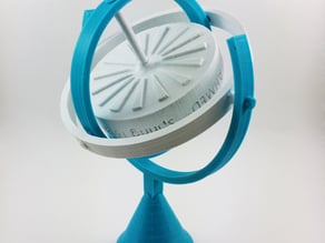
While you were doing that, I was visiting Thingiverse to see what they might have in ready-to-print gyroscopes. There were a number of offerings. I have chosen the two which seemed closest to the example given in the Physics animation.
The example above is interesting because of its professional appearance (a) and (b) the similarity of the rotor to what a passenger section might look like.
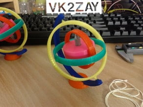
The version below was marked as a 'toy gyroscope". I included it because it appears to be a bit simpler to print and assemble.
A distinct advantage of the gyroscope design is the fact the disk can be set spinning so the axis is lined up with that of the Solar System, and thus the edge of the habitat module will always be pointing toward the Sun. When the ship outside the disk is not performing thrust maneuvers, it can be positioned so that the bulk of it lies between the Sun and the spinning habitat.
***
I note your review of the counter rotating design advantages.The gyroscope design has ** really ** caught my attention at this point.
In ** that ** design, the habitat module can be spun up and sealed for the trip to Mars, and trips "outside" would only be needed in an emergency.
(th))
Offline
Like button can go here
#30 2020-08-15 10:39:19
- SpaceNut
- Administrator
- From: New Hampshire
- Registered: 2004-07-22
- Posts: 30,761
Re: Big Wheel Gyroscope Space Transport
Reaction motors on the ISS are used quite often to save on thruster fuels.
Offline
Like button can go here
#31 2020-08-15 10:39:46
- SpaceNut
- Administrator
- From: New Hampshire
- Registered: 2004-07-22
- Posts: 30,761
Re: Big Wheel Gyroscope Space Transport
For SpaceNut re #54 ...
Thanks for the reminder of momentum wheel use on the ISS ... I found a lengthy discussion on Stack Exchange ...
https://space.stackexchange.com/questio … ment-gyros
In the case of the ISS, the drag of the atmosphere is a factor that would not apply to a Mars bound passenger vessel, but apparently it is not a significant factor. What seems to be the main driver of need for station orientation changes is arriving visiting space craft, and (I gather) the docking requirements, which would require a station that holds position for an extended period, while the approaching vessel eases forward.
The discussion includes speculation on the frequency of expenditure of fuel to desaturate the wheels. No doubt NASA has precise numbers somewhere.
One impression I came away with is that management of station momentum must be a full time job of at least one NASA employee, and perhaps more.
(th)
Offline
Like button can go here
#32 2020-08-15 10:40:13
- SpaceNut
- Administrator
- From: New Hampshire
- Registered: 2004-07-22
- Posts: 30,761
Re: Big Wheel Gyroscope Space Transport
tahanson43206,
The mass wheels failed because they were using steel ball bearings. During extreme space weather events, you basically had "spot welding" going on between the steel ball bearings and bearing cages. If the bearings were ceramic, no "spot welding" occurred. In any event, if you "spin down" the gravity wheels during thrusting or docking maneuvers, then you don't have to concern yourself with the effect of the counter-rotating masses on those maneuvers.
The design I selected, which is not "my design", strictly speaking, uses adequate structural mass to provide passive shielding against CME or SPE, as well as the ability to absorb minor MMOD impacts by not flying to / from Mars at insane speeds. To supplement the passive shielding, it also electromagnetically inflates an electrostatic / charged particle "bubble" around the ship to deflect protons and most light ion GCR. The fusion drive and electromagnetic / electrostatic bubble are both work products of NASA and MSNW LLC. The Sr90 direct thermal SCO2 RTG is a work product of US DOE and various contractors.
This space-based frigate design would not precisely resemble the Star Trek "Stingray" concept artwork stand-in, though it would be substantially similar in appearance. There's no "main deflector dish" in my design, for example, and the engineering section of the hull would be shaped with aerodynamics as one of the design criteria. If I was purely interested in an in-space-only design, then it would consist of a pair of counter-rotating wheels with a spherical or cylindrical center section for the power / propulsion systems and cargo. We could certainly go that way with the design and that would optimize the structural mass to put more space background radiation shielding mass where it's needed most, but then it would have to be assembled in space, rather than being fitted out in space, and a special shadow shielding arrangement devised to deal with the neutron radiation from the fusion drive. Keeping distance and shadow shielding mass in the form of thick metal fuel tanks and hull sections between the crew and the fusion engines was another benefit of the Stingray design. I didn't have to work out a separate shielding arrangement for the crew, as with the "counter-rotating steering wheels connected to a beach ball" design.
If the people want the in-space-only mass-optimized design vs the Star Trek starship design, then I say we give them what they want. There's benefits to both designs. I'm somewhat ambivalent about the final design. I don't know what the "best" solution "looks like". I do know that Star Trek ships catch the attention of young people. A weird-looking counter-rotating steering wheels / beach ball designs probably won't.
Recall that I said the ship would be approximately half the size of the Stingray concept ship. A ship of that size is just big enough to squeeze in a pair of counter-rotating gravity wheels in the saucer section with the minimum diameter required to comfortably deliver 1g at 4rpm. By calculating the internal volume of the design, it also happened to meet NASA's standards for volume per crew member for long duration space flight for 250 crew. Therefore, that was the design criteria that set minimum size for the ship and acceptable head count. There's still plenty of internal volume for the rest of the ship's systems and outsized cargo in the engineering section of the hull.
Offline
Like button can go here
#33 2020-08-15 10:40:48
- SpaceNut
- Administrator
- From: New Hampshire
- Registered: 2004-07-22
- Posts: 30,761
Re: Big Wheel Gyroscope Space Transport
For kbd512 re Post#56
Thank you for insight into bearing failure in space momentum wheel designs.
SearchTerm:FailureOfBearingsInSpace http://newmars.com/forums/viewtopic.php … 09#p170909
The designs you've selected and combined into your version seem worth developing further.
***
In continued reply to RobertDyck about the gyroscope concept that was revealed by the Physics video in your recent post ...I thought about the design overnight, and realized that only one frame is required for a deep space vehicle, instead of the three frames that are required for a gyroscope orientation reference in a vehicle.
In fact, in Space, only one half of a circle is required.
I'll try to make a sketch that shows what this would look like.
In words, the spinning habitat would be pinned at both ends of the axle by bearing housings capable of transferring force between the external ship (propulsion, fuel, storage, navigation, communication, etc) and the spinning habitat.
In this concept, the habitat would never stop spinning throughout a voyage, regardless of the number of thrust maneuvers that might be required.
The propulsion unit would be able to crawl up or down the arch of the half ring to position itself where needed to provide thrust in the desired vector.
Furthermore, the propulsion unit would translate around the spinning habitat so it is in the plane where thrust is to be applied.
As suggested in earlier posts, when the propulsion unit is not performing thrust maneuvers, it can move itself to a position between the habitat and the Sun, to provide additional shielding for the habitat.
It is even possible to imagine swapping out the propulsion unit for a newer one, if the system is designed to allow it.
Thus, the habitat would be buttoned up for the trip to Mars, and there would be no load on the bearings except during thrust events.
kbd512 ... I realize it may not be practical for you to make a sketch of your vision, but if you run across a link to artwork that is similar, it would surely be of interest to NewMars readers.
Edit#1: After re-reading the description above, I realized that if the propulsion unit takes up a position between the Sun and the spinning habitat, the bearings at the tips of the habitat axle would have to deal with rotation, even though there is no force being applied between thrust events. Thus, a small investment of energy would be needed to maintain the position of the propulsion unit, but it is possible to imagine an electric (magnetic) solution to this problem, which would allow precious mass to be saved for trajectory changes.
Edit#2: There is a slide show at the Thingiverse shop at the link below. The "wishbone" shape is at the right in the display.
It is that shape I am imagining as the link between the rotating habitat and the propulsion unit.
https://www.thingiverse.com/thing:1545662
Edit#3: ThingiVerse is a share ware Open Source environment. I downloaded the plans for the gyroscope, as shown at the link above.
Gyroscope (https://www.thingiverse.com/thing:1545662) by ArtiBoyut is licensed under the Creative Commons - Attribution license.
http://creativecommons.org/licenses/by/3.0/I'm thinking of using the rotor and the outermost yoke, to try to make an image to illustrate what an interplanetary ship based upon the gyroscope model might look like.
Edit#4: In recognition of the hard work invested in the gyroscope design which I've downloaded, for an Interplanetary Ship model, here is a credit:
Gyroscope by ArtiBoyut
Published on May 6, 2016
www.thingiverse.com/thing:1545662(th)
Offline
Like button can go here
#34 2020-08-15 10:42:12
- SpaceNut
- Administrator
- From: New Hampshire
- Registered: 2004-07-22
- Posts: 30,761
Re: Big Wheel Gyroscope Space Transport
This is a follow up to Post#57
The gyroscope sample from the ArtiBoyut group on Thingiverse turned out to be relatively amenable to the new purpose I have in mind.
Here is an image that shows the four components from the original model that can be adapted for an Interplanetary Passenger Transport.
The idea that stimulated this study was kbd512's vision of counter rotating habitat modules in a Startrek Enterprise (like) form. However, it was RobertDyck's investigation of gyroscopes that led to the insight that an interplanetary vessel only needs one yoke to deliver thrust to a rotating mass, in the environment of free space.
Please note: The original model has text on the exterior of the habitat module. I don't know what that text is, at this point, but think it may be the identification of a university where the model was created.
Edit#1: The view of the Interplanetary Transport shown above is from the perspective of the navigator in the propulsion section. The navigator can rotate the propulsion unit around the axis of rotation, and slide the propulsion module left or right along the yoke framework, to insure that thrust is delivered as needed. The thrust will be transferred to the rotating habitat via the roller bearings in the intersection of the yoke and the axle.
A detail that came to me as the model came together, is that entrance to or egress from the habitat module is possible during flight, via ports in the axle.
The location for ports that makes the most sense to me is at the ends of the axle. A small "captain's gig" can exit the propulsion module and "fly" to the docking port on the end of the axle. Thus, the crew can live in the habitat module but travel to the propulsion module as needed to make physical adjustments. Otherwise, I would expect all control activities to be managed via electronics from the habitat module.
The movie sequence RobertDyck provided from the movie "2001" shows what the docking would look like.
http://newmars.com/forums/viewtopic.php … 57#p170857
In the movie sequence, the ends of the central axle are shown with large openings for arriving ships. The habitat module under "development" here could be fitted with similar openings, which would serve not only for crew movement to the propulsion section during flight, but for interaction with landing craft at Mars.
It is worth repeating (since not everyone reads every post) ... I am NOT interested in any design for an interplanetary transport that anticipates interaction with an atmosphere. To my way of thinking, that idea is so dangerous that no sane person (able to make free decisions) would buy a ticket on a vessel so designed.
The concept I am working on here is for a true Interplanetary Transport, able to provide artificial gravity, radiation protection, comfortable lodgings, acceptable meals and related benefits of travel, and plenty of enrichment opportunities while the vehicle is in transit between stations, and while holding at either Mars or the Earth.
Please note that the model shown above does ** not ** include a radiation shield that would be part of the yoke, or details of the propulsion model.
Since this is a Blender model, I am open to suggestions for added features forum contributors might recommend. While I have limited experience setting up animation, I have a rudimentary understanding of how animation might be provided to show the habitat module rotating, and the propulsion module adjusting position in order to carry out a thrust maneuver.
(th))

Offline
Like button can go here
#35 2020-08-15 10:42:52
- SpaceNut
- Administrator
- From: New Hampshire
- Registered: 2004-07-22
- Posts: 30,761
Re: Big Wheel Gyroscope Space Transport
If there is no rotating joint. there need be no leaky seal risk. That argues very strongly for one-piece designs.
GW
Offline
Like button can go here
#36 2020-08-15 10:43:26
- SpaceNut
- Administrator
- From: New Hampshire
- Registered: 2004-07-22
- Posts: 30,761
Re: Big Wheel Gyroscope Space Transport
GW,
If there are counter-rotating joints, then we can also put airlocks between them to minimize leakages. There's no such thing as a "leak-free" design, even with the non-rotating joints of the ISS. The leakage rate is so low that it's manageable and that's all that need be accomplished for this design to work. We could have a multitude of Aluminum alloy torus segments bolted or welded together and then put a flexible membrane or liner on the inside that maintains internal pressurization by pressing against a smooth inner torus wall.
Offline
Like button can go here
#37 2020-08-15 10:43:56
- SpaceNut
- Administrator
- From: New Hampshire
- Registered: 2004-07-22
- Posts: 30,761
Re: Big Wheel Gyroscope Space Transport
The ship design shown in mockup form in post #58 has ** NO ** seals that can leak at the points of rotation.
The design is evolving (of course) ... the most recent addition was docking ports in the ends of the axle.
Thus, leakage would occur ** only ** when the docking ports are activated.
(th)
Offline
Like button can go here
#38 2020-08-15 10:44:25
- SpaceNut
- Administrator
- From: New Hampshire
- Registered: 2004-07-22
- Posts: 30,761
Re: Big Wheel Gyroscope Space Transport
SpaceNut,
We need SpaceX and NASA to fund and build a fully reusable super heavy lift launch vehicle first. After that's done, then we'll use Starship to construct true interplanetary transports. If it were up to me, Starship would be a 15m diameter "fat stack" for comparatively "short" rockets with better stability during landing.
Anyway, a pair of tori 15mm thick, with a major radius of 52.5m and a minor radius of 3m, would weigh 1,172,486kg if they were made from 2219 Aluminum alloy (the same alloy that the ISS modules are made from). This would be for the "pair of three-spoked counter-rotating steering wheels connected to a beach ball engineering / propulsion section" hull design. That's just for the gravity wheels, not the spokes, nor anything else inside them, nor the "beach ball" / "engineering section". At least a dozen Starship cargo flights would be needed to deliver the materials to orbit. Even if the gravity wheels need to be 25mm thick, which burns through the entire projected dry mass for the ship (1,954,145kg), we can still manage to deliver 1,000t of cargo per flight.
Since Elon Musk is planning on sending 3 BFS to Mars and that would require at least 18 flights, I figure we can build these ships and deliver a hell of a lot more people and cargo at each launch opportunity. We can deliver at least 10 times as much tonnage, per ship, assuming he intends to launch 3 Starships at every opportunity.
Edit:
The pressurized volume of the pair of spinning wheels would be 18,654m^3 / 658,1744ft^3, equivalent to more than 14 AN-225 cargo holds. According to NASA, that meets the minimum volume requirement for 746 people. If we were to compromise and only send 500 people per vehicle, their net habitable volume falls between Salyut and Mir. We'd have to increase the power and propulsion system mass to do this, but it still looks feasible.If we built ten of these ships, it'd still take 200 launch opportunities to send 1,000,000 people to Mars. However, we could ultimately send 100,000 people in about half a human lifetime. If 6 nations built 10 ships, then we'd need 33 launch opportunities to send 1,000,000 people.
Using nuclear reactors and larger ships with larger gravity wheels, we could feasibly send 10,000 people per ship. If Elon Musk is correct about $10/kg, then a 25,000t nuclear powered ship should only cost $250M to launch. That's basically the cost of a wide-body airliner. Given its simplicity, each ship might cost $1B to construct. If we increase NASA's budget by $2B, then we should be able to construct / launch / crew a ship per year. We could also do crewed missions to Jupiter / Saturn / Uranus / Neptune. There's little reason not to explore and colonize all of the planets.
Offline
Like button can go here
#39 2020-08-15 10:44:59
- SpaceNut
- Administrator
- From: New Hampshire
- Registered: 2004-07-22
- Posts: 30,761
Re: Big Wheel Gyroscope Space Transport
Radiation: I suggested orienting the ring so one side always faces the Sun. That means radiation shielding is only required on one side wall of the ring. None on the outer surface (floor) of the ring. None on the inner surface (ceiling) of the ring. None on the dark side of the ring. My ship for 1,000 passenger, ring width 19 metres plus outer wall, but height 2.8 metre (8 feet) ceilings. So this minimizes radiation shield surface area.
Your idea of the half ring mad me think. The main engine can apply thrust to the hub in any direction. It doesn't need a large semicircular ring, it can be close to the hub. In fact, we could have several engines aimed in different directions, but all oriented so the vector of thrust first through centre of ship mass. Simply use differential thrust to for course correction. This doesn't require full thrust, course correction engines can be smaller.
Offline
Like button can go here
#40 2020-08-15 10:46:13
- SpaceNut
- Administrator
- From: New Hampshire
- Registered: 2004-07-22
- Posts: 30,761
Re: Big Wheel Gyroscope Space Transport
For RobertDyck re #66
Thank you for the reminder of your suggestion of keeping the edge of the habitat aligned with the Solar plane. I have tried to give credit for ideas I am using, but the members of the forum are occasionally too productive for me to keep up.
While I am closely following developments in your Large Ship topic, and this one, occasionally I may fail to properly acknowledge ideas I am incorporating in my design, so I appreciate the reminder!
My immediate next addition to the Gyroscope Transport is a U shaped form that would extend from the propulsion unit to shield the habitat during non-thrusting flight, which is most of the time. I'm hoping to find previously posted descriptions of the optimum material for shielding ... my recollection is that material that contains a lot of Hydrogen is favored, and that there are solid materials made from hydrocarbon that are well suited for the application.
A large structure filled with such material would serve as a radiation shield most of the time, but it also represents a stored backup of usable materials (Hydrogen, Carbon, etc) that could be consumed in an emergency.
I'll have to study your idea for propulsion ... could you make a drawing to show what you have in mind? The word picture that generates images in my mind (or any reader of the forum) may differ from what you are "seeing" in your mind's eye.
One change I am planning to make as soon as possible is to bring the thrust from the propulsion unit closer to the hub of the axle of the rotating habitat.
An engineering detail for the Gyroscopic Transport is the vulnerability of the bearing traces where thrust is transferred to the rotating habitat, which (I am guessing) would mass 1000 tons for the smallest possible version, and many thousands of tons for larger versions. Thus, I am anticipating the need for a propulsion system that provides modest thrust for an extended period instead of massive thrust for a short period, which is the existing standard practice.
(th)
Offline
Like button can go here
#41 2020-08-15 10:46:39
- SpaceNut
- Administrator
- From: New Hampshire
- Registered: 2004-07-22
- Posts: 30,761
Re: Big Wheel Gyroscope Space Transport
Calliban,
I presume that this new power / propulsion concept is intended to do away with the requirement for some of the hardware in order to initiate fusion, but also to combine parts of the power and propulsion system?
In the MSNW design, fusion was initiated by a supersonic implosion of the foil liner around the D-T pellet using a bank of super capacitors. In this concept, if I understand correctly, we're using fission to sustain fusion.
How do we expel the vaporized Aluminum fuel to produce thrust?
Instead of dozens of individual electromagnetic compressors that initiate fusion, does this new concept permit us to design a single "main engine"?
tahanson43206,
I guess the shielding material could be consumed by another process that requires reaction mass or coolant or its own radiation shielding, but it wouldn't be suitable for human consumption if that's what you were thinking. The radiation shielding materials, in most cases, would need to remain in place.
Offline
Like button can go here
#42 2020-08-15 10:47:59
- SpaceNut
- Administrator
- From: New Hampshire
- Registered: 2004-07-22
- Posts: 30,761
Re: Big Wheel Gyroscope Space Transport
For SpaceNut re possible new topic in Interplanetary Transportation topic ...
Here is an updated view of a Gyroscope Interplanetary Transport.
Edit@20:08: I've decided to reconsider the name in light of the similarity of this evolving design to the "Big Wheel" toy.
While the concept is evolving from the concept of a gyroscope, the appearance of the modified "ship" is much more reminiscent of a "Big Wheel" than it is of a Star Trek(tm) design.
This concept arises from ideas posted by RobertDyck and kbd512.
I'd like to invite you to consider setting up a topic for this hybrid concept. Each of them is hard at work developing their visions.
I'd like to try to catch this moment in the flux of creativity and focus on developing this version of their ongoing work.
In this version of the Interplanetary Ship Model, I've added a radiation shield that is part of the Propulsion Unit.
As a reminder, and for anyone seeing the model for the first time:
1) kbd512 suggested mounting habitat modules in a form factor that looks similar to the Startrek Enterprise.
2) RobertDyck suggested rotating a habitat edge on to the SunThis model incorporates those ideas into a system that can be spun up to give passengers artificial gravity during transit to Mars.
In addition, the design incorporates the capability of moving the propulsion unit so that when chemical (or other) thrust is needed, the force can be applied to the bearings between the Yolk Axle and the Habitat, so that the entire assembly is accelerated smoothly in the desired direction, without disturbing the rotation of the habitat.
Finally, this updated version includes a radiation shield that is part of the propulsion unit. When the propulsion unit is not thrusting, it will be aligned so that the central axis of the propulsion unit is parallel to and aligned with the line between the center of the Sun and the center of the Habitat.
Entrance to and exit from the Habitat would be via ports in the two ends of the Yolk Axle. There would be no opportunity for leaks at any other location. The exit ports could be used for crew movements during flight, and for loading and unloading the Habitat at destinations.
Edit#1: Credit for the gyroscope model I am using for this illustration goes to the designers who posted it on Thingiverse.
Specific details are posted earlier in this thread.Edit#2: My first attempt to add a propulsion module to the base of the propulsion stub was not successful. Working in Blender, the boolean operations to try to merge a new object into the structure created by the Thingiverse team resulted in massive damage to the model.
One slicer gave a count of 1.5 million errors. I'll try again, of course. Extrusion of the base of the existing stub may work.
(th))

Offline
Like button can go here
#43 2020-08-15 10:48:47
- SpaceNut
- Administrator
- From: New Hampshire
- Registered: 2004-07-22
- Posts: 30,761
Re: Big Wheel Gyroscope Space Transport
Calliban,
For this to work, we need a very powerful electromagnet to operate efficiently inside of a very high thermal power output fission reactor. That's a pretty tall order. The electrical resistance of the best conductors increases dramatically by the time you reach typical operating temperatures. If that operational issue wasn't a particularly difficult problem to solve, which it is, then repair or replacement of such coils would be.
tahanson43206,
The entire point behind implementing high-Isp fusion rockets and minimum energy trajectories is to deliver the most payload tonnage using the least propellant tonnage. There's no technical reason why we can't move a 5,000t or a 25,000t ship using low-Isp chemical propellants, but the ship would necessarily become a giant thin-skinned gas tank.
Supplying the power is the actual problem. The lightest practical solution to supply 10MWe continuously for 2 days appears to be Sr90 RTGs combined with SCO2 gas turbines and hull plating as the radiator / heat sink. That means there are no insurmountable engineering challenges.
I've ball-parked the system masses for the following solutions:
1. PV only - array must flex or be so rigid that it doesn't flex very much and can't spin at the size required
2. PV plus Lithium-ion - ship becomes a giant battery rather than a giant gas tank
3. PV plus Carbon fiber flywheels - takes a couple of months to spin up the flywheels
4. CSP only - same problems as massive PV array and likely impractical for ship orientation during thrusting
5. CSP plus Carbon fiber flywheels - solves CSP only problems
6. PV and regenerative PEMFC using LOX/LH2 - requires storing low 100s of tons of cryogens, cryocooling
7. Sr90 RTG plus SCO2 gas turbines - quite heavy for the overall power-to-weight provided, yet still better than the alternatives
8. LEU UO2 fueled fission reactor* - very heavy shielding required, no better than the PV and fuel cell solution*Note: I was using numbers from a past NASA design with a traditional BeO reflector, traditional NaK coolant with secondary SCO2 loop for power takeoff, and traditional shielding materials like Water and Tungsten, under the auspices of "use what's been well-proven to work in the past".
The end goal here is to move lots of people and cargo to other planets at reasonable speeds while providing artificial gravity and adequate radiation and space debris protection, not to go broke on fuel costs associated with shipping. Aluminum is readily available here and on other planets. Here in America, we can collect the Aluminum waste we toss into the trash every year and vaporize it for propulsion. I want to power our space fleet using trash.
CO2 is readily available for coolant loop top-up and splitting into CO/O2 for retro-propulsive landings. Sr90 and D-T are readily available waste products from fission reactors. There's no fission reactor aboard the smaller vessels and no reason to think we can't make RTG units "reentry proof", same as all other existing RTG units used in space.
Random Thought:
If we built RTG-powered cruisers (25,000t ships) and sent cargo only on CSP / flywheel powered frigates (5,000t ships) we could reduce the number of nuclear powered ships and increase the cargo tonnage delivered by deleting the giant gravity wheels from the uncrewed or minimally crewed frigates. Conceivably, orbital CSP solar power stations could "recharge" the flywheels of the frigates in orbit around Earth / moon / Mars / Venus to eliminate the expensive photovoltaic panels and their life limitations due to radiation degradation. Lockheed-Martin had the right general idea with the "Mars Base Camp" concept. We need orbital power facilities to reduce total IMLEO / IMLMO tonnage. If we did that, then we may not need RTG or fission at all, which would remove another technological hurdle towards implementation. We could also have "fast frigates" for continuous cargo delivery of high priority cargo between crewed missions, irrespective of the orbital position of Mars in relation to Earth.
Offline
Like button can go here
#44 2020-08-15 10:49:30
- SpaceNut
- Administrator
- From: New Hampshire
- Registered: 2004-07-22
- Posts: 30,761
Re: Big Wheel Gyroscope Space Transport
For SpaceNut re #59
SpaceNut wrote:list post number to split out to create new gyro ship topic with respect what remains making sense to fast flights to mars....
nice human pedal powered "bigwheel"Thanks for your encouragement!
As I understand your guidance, you'd be interested in seeing a list of posts to be copied to a new "Big Wheel Gyroscope Space Transport" topic.
I'll start working on that! My first inclination is to look for the post where kbd512 first tossed out the counter-rotating flat disk concept.
However, I'd like to start with a post that I can edit, so the top of the new topic can be updated from time to time to help future readers to understand what the topic is about, and where to find specific contributions by specific members.
***
I'm not convinced this subtopic belongs in Fast flights to Mars, because it is about a vehicle design that in itself does not necessarily contribute to speed.What the "Big Wheel" design does do is to contribute to (1) artificial gravity for passengers and crew, (2) radiation protection for both, (3) other aspects of space flight between planets as the need becomes apparent.
Edit#1: Thanks for noting the image of an "adult" Big Wheel << grin >>
(th)
Offline
Like button can go here
#45 2020-08-15 10:51:58
- SpaceNut
- Administrator
- From: New Hampshire
- Registered: 2004-07-22
- Posts: 30,761
Re: Big Wheel Gyroscope Space Transport
ok all listed posts copied but there are more that have been made since
topic focus is a ship that spins the crew area and not the total ship
let me know if a post needs to be altered
Offline
Like button can go here
#46 2020-08-15 12:34:05
- tahanson43206
- Moderator
- Registered: 2018-04-27
- Posts: 24,791
Re: Big Wheel Gyroscope Space Transport
For SpaceNut re new topic!
SearchTerm:Anchor TopicBigWheel
SearchTerm:Topic AnchorBigWheel
SearchTerm:BigWheel Gyroscope
SearchTerm:BigWheel Transport
Thanks very much! That was a ** lot ** of work, and I will try to keep the topic going as a worthy complement to the work RobertDyck is doing with his Large Ship topic, and as an appreciation of the many suggestions contributed by kbd512.
Thanks too, to GW Johnson, for many tips and suggestions.
At the moment, I am hoping to learn how to embed cylinders inside the large habitat shape, using Fusion 360.
The 9 meter diameter Starship second stage would fit in a ring of 34 instances around the perimeter of the 56 meter radius ship.
Each of these would be fully capable of serving as a lifeboat in case of need, but would otherwise be configured as spacious accommodation for first class passengers.
Facilities inside the perimeter would be capable of supporting passengers and crew at lesser amounts of artificial gravity.
Edit #1: This is the first post made by tahanson43206 in the new Big Wheel topic created by SpaceNut.
Update 2020/08/18 ... Design of the Big Wheel Gyroscope Space Transport began with the initial suggestion of a radius of 56 meters.
This figure came from GW Johnson, who computed this as the radius that would yield 1 gravity of simulated gravity at 4 RPM.
The 4 RPM figure arises from research using human subjects (citation needed).
In any case, the radius of 56 turns out to be slightly too small to accommodate 36 Starship rocket bodies, if they were arranged in parallel around the inside perimeter of the Big Wheel habitat. A radius of 57 would accommodate 36 rocket bodies, with just under a meter of space between them.
Space between the rocket bodies is needed for structural components of the Big Wheel itself, and to permit the rocket bodies to dock inside the structure for a trip to or from Mars. It is possible that the space needed between rocket bodies may turn out to be greater than this radius provides, so an adjustment can be made at that time.
In the mean time, it is worth noting that the Big Wheel design can start with as few as three rocket bodies.
The natural progression of addition of rocket bodies would be 3, 6, 9, 12, 15, 18, 21, 24, 27, 30, 33 and the full complement of 36.
The physical dimensions of the Yoke component, and the Propulsion unit would not change throughout the progression from 3 to 36.
The strength and capability of those components would be increased as the Habitat load increases.
Edit#1 2020/08/30 ... The Big Wheel design assumes it will be spun up for the trip to Mars, and despun upon arrival to allow the Starships in the docking cradles to exit. Because of the great mass of the rotor, a great deal of mass would be expended performing these operations.
A possible solution is to pair up Big Wheels .... At departure from Earth, the two would work against each other's momentum to drive rotation in opposite directions, via a shared shaft. Upon arrival at Mars, the two would re-connect and then employ the same shared axle to draw energy out of the system.
That energy needs to be stored, so provision for storage of energy on that scale would need to be part of the design.
The concept is similar to the contra-rotating habitats idea of kbd512, but the two habitats would fly separately. Thus, the mass to be moved by the propulsion units would be half what if would be if the habitats were combined.
(th)
Last edited by tahanson43206 (2020-08-30 08:00:37)
Offline
Like button can go here
#47 2020-08-15 13:16:13
- SpaceNut
- Administrator
- From: New Hampshire
- Registered: 2004-07-22
- Posts: 30,761
Re: Big Wheel Gyroscope Space Transport
here are a few more posts
Re GW Johnson post on Artificial Gravity [56 meter radius baseline - 4 rpm - 1 g]
http://newmars.com/forums/viewtopic.php … 70#p170670
SearchTerm:ArtificialGravity
For Big Wheel Passenger Transport model study
Edit#1: Artificial Gravity calculation examples: https://www.school-for-champions.com/sc … zZxa1RDsuo
A Big Wheel habitat built according to the 56 meter radius example would be 112 meters in diameter, or 367 feet and change.
For RobertDyck (when you get back from your trip ...) How thick would you want a habitat to be constructed for your comfortable accommodations concept?
I'm asking because I am restarting the Big Wheel model from scratch.
(th)
Offline
Like button can go here
#48 2020-08-15 13:16:40
- SpaceNut
- Administrator
- From: New Hampshire
- Registered: 2004-07-22
- Posts: 30,761
Re: Big Wheel Gyroscope Space Transport
If all you want is 0.38 gee, then all you need is 0.38*56m = 21.2 m radius at the same known-to-be-tolerable 4 rpm spin rate. That's fine for folks going from Earth to Mars, because 0.38 gee is what they will have when they get there. They will be well-acclimatized to it.
Might ought to think about folks returning from Mars back to Earth. They will face 1 full gee when they get there, and we should all have doubts about 0.38 gee being enough for them to accommodate it upon arrival.
Now 4 rpm is about the max that most folks seem to tolerate for long periods of time. A few can be trained (at great expense) to tolerate higher spin rates, but usually for shorter times. Nobody really knows whether higher rates are tolerable for timelines measured in months.
What that says is you want a 1 gee design at 4 rpm, and just spin it slower for 0.38 gee on the outbound voyage to Mars. Spin it at 1 gee for the return voyage to Earth.
Maybe you don't want a wheel because 56 m is too big. There is end-over-end, which is also stable. That geometry is more restrictive, but 2*56 m = 112m lengths are far easier to reach than are 2*56m = 112m diameters.
Although, if you believe the old Project Orion explosion-drive designs, those ships are more efficient if they are around 100 m diameter and 300-400 m long. 15-20,000 tons corresponds to 15-20,000 sec effective Isp, at ship accelerations in the 2-4 gee range. Short burn, then coast and spin-up for artificial gravity. Simple.
GW
Offline
Like button can go here
#49 2020-08-15 13:19:31
- SpaceNut
- Administrator
- From: New Hampshire
- Registered: 2004-07-22
- Posts: 30,761
Re: Big Wheel Gyroscope Space Transport
This is for RobertDyck re topic ...
Best wishes for your safe return from your current travel adventures in the far northern reaches of Canada!
In anticipation of your safe return, I am adding to my request for advice and counsel for design of the Big Wheel Passenger Transport vehicle.
I'm starting with the figure of 56 meters radius, published by GW Johnson in another topic.
In that post, GW Johnson reported 56 meters as the radius needed for the floor of a rotating habitat to deliver 1 g of simulated gravity (Void's term) at 4 rpm.
I am using that figure as the starting point for design of a 3D printable model. At 1:100 scale, that size is quite useful for a design with the tools I have available.
In a previous post, I asked you for your estimate of the optimum width for the floor of a first class cabin that stretches across the entire "floor" of the habitat.
In anticipation of future versions of the habitat, to offer slower and slower rpm as inducements for passengers to select one space line over another, I am expecting the width of the habitat would remain constant while the diameter would increase.
In a work session way from the forum, I made a list of issues/questions/concerns/opportunities ...
Item 1 is the width question, already described
Item 2 is: Plan for Lifeboat capability?
In a separate topic (Fast to Mars) kbd512 has described his vision of a large ship that could glide through an atmosphere on a one-way landing attempt if necessary. In this topic, and pending SpaceNut creating a new topic just for Big Wheel, I am imagining that the "floor" of the habitat would be filled with individual spacecraft/lifeboat/mobile-home-like compartments.
As a stretch exercise, I can imagine SpaceX Starship cylinders adapted for this purpose. The length of a starship is reported to be 50 meters.
Size
Second stage – Starship
Length 50 m (160 ft)
Diameter 9 m (30 ft)
Empty mass 120,000 kg (260,000 lb)SpaceX Starship - Wikipedia
For what it's worth, the ratio between 50 meters and 112 meters is 2.24
If you were to select 50 meters as the width of the habitat disk, the cylinder generated in a 3D printer design program looks agreeable to my eye.
I'll try to post an image of the 50:112 cylinder later today.
Edit#1:
Getting back to the lifeboat design question ...
If the habitat is designed to accommodate a number of Starship second stage vehicles as passenger cabins, then there would be design questions to address for how to mount them in the circumference of the habitat so they can be released if need be with minimal difficulty. I would imagine a combination of manual locking mechanism (for backup) as well as explosive bolts for emergency deployment would make sense.
This post is getting longish, so I'll continue in another ...
(th))

Offline
Like button can go here
#50 2020-08-15 13:20:38
- SpaceNut
- Administrator
- From: New Hampshire
- Registered: 2004-07-22
- Posts: 30,761
Re: Big Wheel Gyroscope Space Transport
This is a continuation of Post #165 for RobertDyck
Other questions/issues/opportunities would include:
3) Plan for self sufficiency in flight (assuming 6 months using the generally accepted minimal energy path)
I would expect use would be made of the volume in the cylinder inside the outer ring of passenger cabins.
What stores of what items would be needed to insure a comfortable flight, without the need to open a service door to the habitat.
(as a reminder, the Big Wheel Passenger Transport design currently assumes only two sites where vacuum is exposed, at the ends of the axle of rotation)
I can imagine water (for example) moving from a reservoir (or several) of clean, potable water into a waste tank (or several) for cleaning service at a major destination port (such as Phobos or LEO).
4) Power in flight?
I can imagine a set of solar panels for normal power supply, as well as for topping off emergency batteries or other storage devices.
However, in anticipation of possible failures of the solar panel system, or an emergency, the passenger compartments(lifeboats) should be capable of sustaining themselves independently for some reasonable period of time.
5) Communication ... this subtopic has multiple aspects
a) With the propulsion/navigation unit
This would be a very high capacity Internet service for crew inside the habitat to be able to direct the activity of the propulsion unit.
(as a reminder, it is anticipated the crew could use a "Captain's Gig" for movement between the habitat and propulsion unit if necessary)
b) With Earth ... large dish antenna would seem appropriate ... these could be mounted on the Propulsion unit
c) With Mars ... the same or perhaps other dish antenna
d) With any other location ... these might be smaller and easy to maneuver as needed6) Science enroute
The crew and passengers will have six months (or so) for useful activity while in transit. As a reminder, Benjamin Franklin carried out scientific research while travelling between the North American continent and Europe.
Mapping the Gulf Stream
Although Spanish explorers had described the Gulf Stream, Franklin, fascinated by the fact that the sea journey from North America to England was shorter than the return trip, asked his cousin, Nantucket sea captain Timothy Folger, to map its dimensions and course. Franklin published this map and his directions for avoiding it in the Transactions of the American Philosophical Society in 1786. Systematic research, conducted by the U.S. Coast Survey, of the Gulf Stream did not occur until 1845.
Benjamin Franklin. “Maritime Observations and A Chart of the Gulph Stream.” in Transactions of the American Philosophical Society. Philadelphia: 1796. Engraved map. Geography & Map Division, Library of Congress (40A) [gmd9/g9112/g9112g/ct000136]
Bookmark this item: //www.loc.gov/exhibits/franklin/franklin-scientist.html#obj40a
In the case of passengers and crew transiting from Earth to Mars and back, there will be ample opportunity to make astronomical observations in a wide variety of wavelengths. In addition, the moving transport could be a node in an interferometer:
VLBI reveals the universe in amazing detail | Astronomy ...earthsky.org › astronomy-essentials › how-vlbi-reveals-...
Jul 5, 2012 - Very Long Baseline Interferometry, or VLBI, is a powerful technique in radio astronomy. By linking together widely separated radio telescopes, VLBI allows astronomers to see the universe in more detail than ever.(th)
Offline
Like button can go here