New Mars Forums
You are not logged in.
- Topics: Active | Unanswered
Announcement
#1076 2022-01-22 19:07:09
- kbd512
- Administrator
- Registered: 2015-01-02
- Posts: 8,533
Re: Large scale colonization ship
tahanson43206,
From what I've read, you simply have to re-download and re-install the application after 1 year has elapsed, but that may not be correct. I've read that from multiple mechanical engineering and research websites.
I have to wait for a response from EPI before determining whether or not they're interested to begin with and what arrangement they're willing to work under.
In the mean time, at least for the spinning top model, it's easy enough to calculate the torque that must be counteracted using simple hand calculations if Robert can provide reasonably accurate mass estimates. A FEA tool that has specific mass distributions would be more accurate. The counter-rotating concept requires more involved calculations, but I will substitute the mass estimate (divide torus volume by total tonnage carried within the torus) to determine what it would be if the torus was a solid / rigid body. Afterwards, we can compute values for what MMOI would be if the mass was all along the outer or inner wall of the torus or cylinder, which is a way to bound what the torque possibly could be if we had some improbable / unrealistic mass distribution within the spinning portions of the respective ship designs.
I need Calliban to tell us what the power / propulsion system mass estimate will be for Robert's large ship.
r2 = radius #2
r1 = radius #1
t = normalized thickness ratio
Iz = moment of inertia in the Z / axial plane
Ix = moment of inertia in the X plane
Iy = moment of inertia in the Y plane
Ix = Iy because this is a thick-walled cylinder rotating in the Z plane
Iz = (m(r2^2 + r1^2))/2 = mr^2(1-t+(t^2/2)), where t = (r2 − r1)/r2
Ix = Iy = m(3(r2^2 + r1^2) + 4h^2)/12
The MMOI formula the 3 spokes leading to the habitation ring is as follows:
Iend = mL^2/3
That is not precisely correct because the Iend is not actually touching the origin / axis of rotation (Robert said the center barrel section is going to be 9m in diameter, same as Starship).
So, start with the thick-walled cylinder formula for the center barrel section, compute MMOI for the spokes as if they were 4.5m offset from the axis of rotation (because they are), then use the thick-walled cylinder formula for the habitation ring, use a separate calc for the mass of the water shield, add them together, and voila! You have a ballpark figure for MMOI.
After you know that, then use the rotational kinetic energy formula:
Rotational Kinetic Energy Calculator
RE = 0.5 * I * ω²
RE is the rotational kinetic energy, expressed in Joules (I normally convert to lb-f or kg-f, though)
I is the moment of inertia of the object, expressed in kg*m²
ω is the angular velocity of the body, expressed in radians per second or in Hertz/RPM (revolutions per minute) after the appropriate units conversion
For the center barrel section and spokes, you can tally up the mass of the atmosphere along with any equipment or other significant mass located inside and treat it like an object of uniform density, or as a thick(er) walled cylinder.
Anyway, I hope Robert finds this useful. He's a programmer like I am, so he can write a script to do this. No advanced CAD program is required to "ballpark" the design MMOI and RE calcs. Once you have your calcs bounded, you can compute minimum and maximum torque required for equally unrealistic configurations of mass distribution, then split the difference, then treat the objects as if they had uniform density (obviously also unrealistic), and that provides the necessary data to work with to determine counteracting torque required. The gyros will need to counteract that torque to prevent precession perpendicular to the axis of rotation. Both of our designs are subject to precession forces.
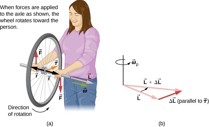
You already saw that 70kWe of continuous power was required to produce 1000kN / 334t of counteracting torque using a 20.1t shipboard gyro unit. I'd wager that gyro's total mass could be reduced by maybe 5t with an Aluminum or composite vs steel enclosure, but you can see how considerable the power and mass is. We'll need banks of these units, many of which will need to be spun up. That was the entire point behind counter-rotation- less deadweight tonnage and electrical power is required. If you already have a nuclear reactor onboard, as Robert's ship does, then this may not matter as much. There is a geometry that maximizes counteracting torque, such as a long lever arm to apply torque to, but then you're back to needing slewing ring bearings. There are nothing but trade-offs here, but I would go for the lever arm solution to avoid needing a lot of mass and electrical power to solve this.
Offline
Like button can go here
#1077 2022-01-22 19:21:39
- SpaceNut
- Administrator
- From: New Hampshire
- Registered: 2004-07-22
- Posts: 30,787
Re: Large scale colonization ship
Typically the registration on the computer will still have tags that are not removed when the software is removed to keep people from reusing the trail ware software. Once can make a copy of the registry pre-install as a means to find the tags or to use as a backup so as to replace the current with the older one. Then try installing it fresh once more after the 1 year time period.
I am concerned that many of the critical parts are going to be segmented which will make things not move smoothly.
Offline
Like button can go here
#1078 2022-01-22 20:17:44
- tahanson43206
- Moderator
- Registered: 2018-04-27
- Posts: 24,952
Re: Large scale colonization ship
For kbd512 re #1076
Thanks for the encouragement to try again with Fusion 360.
It might be possible to start over with a new (fake) user ID, and a clean computer (as SpaceNut suggested).
My investment in ID tahanson43206 over the course of a year was considerable, as shown in the Large Ship topic.
The truth is that I came away from the trial convinced that Fusion 360 is worth the (relatively modest) annual fee, but at this point even that is out of reach.
However, a full year is there for someone wanting to start fresh, and I've recorded a great deal of learning experiences in the Large Ship topic. I ran a quick search yesterday, looking for posts with fusion and 360 by tahanson43206, and the result set was several pages.
***
For RobertDyck .... the video about artificial gravity that Void found included a statement that I thought might be promising for your Unitary design. The statement was that a central shaft of a certain length would be stable, and anything less than that would be unstable.
My recollection is that 2.4 was the magic number, but what that relates to I don't remember.
It seems to me it would be worth while for anyone designing a large rotating structure to look for that advice.
the video is about 30 minutes long, and the length specification was in the second half.
Edit later: AutoDesk made my change my password, but they let me in. My files from the Fusion 360 trial are gone. They are offering a 30 day free trial of Fusion 360. After a free year, 30 days seems like not worth while.
The prices for the paid version are:
Fusion 360
SUBSCRIBE
FREE TRIAL
NEW YEAR. NEW TOOLS
Limited-time offer: Save 30% on Fusion 360 and extensions.
ACT NOW
Integrated CAD, CAM, CAE, and PCB software.
Fusion 360 unifies design, engineering, electronics, and manufacturing into a single software platform.
DOWNLOAD FREE TRIAL
Request a quote: 1-833-843-3437
Fusion 360 pricing options
$1,410 $987/paid every 3 years
$495 $347/paid annually
$60 $42/paid monthly
$495 $347/year
What is Fusion 360?
Fusion 360 is a cloud-based 3D modeling, CAD, CAM, CAE, and PCB software platform for product design and manufacturing.
Design and engineer products to ensure aesthetics, form, fit, and function.
Reduce the impact of design, engineering, and PCB changes and ensure manufacturability with simulation and generative design tools.
Directly edit existing features or model fixtures with the only truly integrated CAD + CAM software tool.
FUSION 360 3D DESIGN & MODELING
3D CAD made easy
Don't let your 3D modeling tools limit your creativity and ability to quickly create multiple design iterations. Fusion 360 enables you to design effortlessly with flexible 3D CAD software.
SEE 3D MODELING FEATURES
Buy Fusion 360
Get integrated CAD, CAM, CAE & PCB on a single development platform. Also includes EAGLE Premium, HSMWorks, Team Participant, and access to consumptive services, such as generative design, cloud simulation, and cloud rendering.
The text "Buy Fusion 360" is misleading ... they mean "rent" ...
Edit even later: Fusion 360 was still on the screen after the password reset, so I logged in ...
It has a message at the top: Expired Subscription. Read-Only.
It occurred to me that the monthly rate of $42 might provide access to the files saved from the free trial period.
If they'll let a subscriber pay for a month at a time, and hold the files between months, I might be able to justify keeping it active.
Edit even later: Holy Moley! They renewed my Educator subscription for a full year!
All my saved files are visible! I was even able to retrieve one of them.
Well! I guess I have to tip my hat to kbd512 for encouraging me to try again.
***
For RobertDyck ... you should be able to get a 1 year subscription to run on your system, now that you have the new video card.
(th)
Offline
Like button can go here
#1079 2022-01-22 22:36:43
- kbd512
- Administrator
- Registered: 2015-01-02
- Posts: 8,533
Re: Large scale colonization ship
tahanson43206,
I don't think you need to do anything except download the new version of the software once per year, or at least that's what the commentary indicated on what hobbyist-type users must do to continue using the free version of the software. The Autodesk company doesn't seem to mind hobbyists learning to use their software, since that will ultimately generate more revenue for the company, as long as nothing they do with it is used to generate revenue. The moment the Autodesk software is used for commercial purposes, then you need licenses. That's just business. You're using their product to make money, so you have to pay them. We're not using any software for purposes of generating revenue, so we should be able to continue to use free software to design a ship.
It'd be great if we could strike a deal with ANSYS for the same purpose, share the design with them (part of the deal with Fusion 360 and ANSYS), as that would give us access to one of the best multi-physics tools for the complex analyses required to account for complex parts geometries and various different forces acting on these ship designs.
To wit, we need a FEA on the major components (hull sections) and critical sub-assemblies (mounting rings and fasteners, unless absolutely everything will be welded- and then you still need to know whether or not the welded assemblies can support a specified load without excessive stress placed upon the welded components) to account for mechanical and thermal stress, we need a CFD-type analysis to determine what constitutes effective radiation shielding for a given proton fluence, thermal-hydraulic analyses for nuclear power and propulsion systems since both ships use nuclear thermal power or propulsion (recall that I stated I intend to use SCO2 for power transfer from the RTGs to Brayton cycle gas turbines to generate electric power), and we need more FEA analyses for load paths if we intend to use high-thrust propulsion systems such as gas core nuclear thermal rocket engines.
For example, the stainless steel hulls of those ISS modules that were provided to NASA were never intended to resist substantial loads placed upon them in the manner we're contemplating, because they were designed to operate in microgravity and launched in the cargo bay of a Space Shuttle, which provided significant structural support. They had to endure a transient of 3g for a Space Shuttle launch, but they were also pressurized to 14.7psi and the load path was through the end plate of the module. When we start filling them with stuff and subjecting them to 0.38g transverse loads, and point loads at that, for most of their design operating life, as well as periodic load transients during periods of thrusting, will that be enough or will fatigue from load cycling damage them? If they ever deform significantly under load, they're done, period.
Take a look at this picture of a MPLM being fabricated from Defense Visual Information Distribution System:
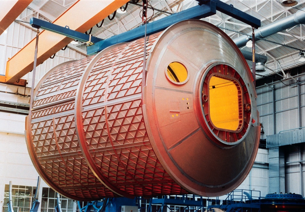
We need to know the exact alloy and gauge of material used. Look at the iso-grid pattern. Was that thing actually all-welded sheet steel or was it carved out of blocks of stainless?
That hatch was most definitely machined from a block of metal. I can see where it was welded because the steel is a different color. That iso-grid doesn't look like it was welded, though. I think it was fabricated the same way that ULA fabricates the Aluminum "potato chips" used in Atlas V first stage propellant tanks. Those are not cheap or easy to fabricate. It's not like taking a piece of plate and hot rotary hammer forging it into a cylinder, the way they make certain types of pressure vessels or components for ships and trains and industrial machinery.
Robert,
Take a look at this (useful ISS design information jackpot for MMOD and structures):
Exponential Deep Space - Space Station Issue #28
There are plenty of other issues to peruse through. It's like someone collected relevant design information and put it in one place.
Offline
Like button can go here
#1080 2022-01-22 23:11:07
- RobertDyck
- Moderator
- From: Winnipeg, Canada
- Registered: 2002-08-20
- Posts: 8,437
- Website
Re: Large scale colonization ship
Wikipedia: Multi-Purpose Logistics Module
Length – 6.6 m (cylindrical part 4.8 m)
Width – 4.57 m
Mass – 4,082 kg empty; 13,154 kg fully loaded
Habitable volume – 31 m³
Material – stainless steel
During launch the pressure inside the module is the same as outside: 1 atmosphere. The module is firmly held in the cargo hold of the space shuttle. Not sure how it was held down, but it had to be attached to the ribs of the shuttle inside the cargo bay. Attachment had to be able to release once the shuttle's arm attached so it could be moved. But during launch from the pad the pressure inside the module is the same as outside, and the difference between empty mass and fully loaded is 9,072 kg. That means MPLM had to hold that much cargo mass during acceleration off the pad and vibration from the SRBs. MPLM Leonardo is now the Permanent Multipurpose Module, it launched 8 times.
Offline
Like button can go here
#1081 2022-01-23 00:42:10
- kbd512
- Administrator
- Registered: 2015-01-02
- Posts: 8,533
Re: Large scale colonization ship
Robert,
If you download node.js and slap the following text in a file and save it, then you can run this JavaScript from the command line:
// mass in kilograms
var m = 350;
// outer radius of cylinder wall, in meters
var r2 = 5.5;
// inner radius of cylinder wall, in meters
var r1 = 5;
// height of cylinder, in meters
var h = 1;
// formula for calculating the moment of inertia for a thick-walled cylinder when the X-Y plane runs through the middle of the cylinder
var Iz = 0.5 * m * (Math.pow(r2,2) + Math.pow(r1,2));
var Ix = (1/12) * m * ((3*(Math.pow(r2,2) + Math.pow(r1,2))) + Math.pow(h,2));
var Iy = Ix;
// unit conversion; 1 rpm = 0.10472 rad/s
var rad_s_to_rpm = 0.10472;
var rpm = 5.675;
// uses revolutions per minute as the input to Omega, versus radians per second
var ω = rpm * rad_s_to_rpm;
// Rotational kinetic energy (RE), expressed in Joules
// I = moment of inertia / mass moment of inertia, expressed in kg*m^2
// ω (Omega) = angular velocity of the object, expressed in radians per second, or revolutions per minute after converting
// RE = 0.5 * I
var RE = 0.5 * Iz * Math.pow(ω, 2);
// unit conversion; 1 kilogram-force meter = 9.8066499997 Joules
var Joule_to_kgf = 9.8066499997;
// output of variable inputs and Iz-plane moment of inertia (cylinder rotating about Z plane running through the "center of the pipe")
console.log('mass m (in kilograms) = ' + m);
console.log('radius #2 / r2 / outer radius (in meters) = ' + r2);
console.log('radius #1 / r1 / inner radius (in meters) = ' + r1);
console.log('Ix-plane moment of inertia (in kilogram-force meter) = ' + Math.round(Ix) + ' kg*m^2');
console.log('Iy-plane moment of inertia (in kilogram-force meter) = ' + Math.round(Iy) + ' kg*m^2');
console.log('Iz-plane moment of inertia (in kilogram-force meter) = ' + Math.round(Iz) + ' kg*m^2');
//console.log('Rotational Kinetic Energy (in Joules) = ' + Math.round(RE) + ' Joules');
console.log('Iz-plane Rotational Kinetic Energy (in kilogram-force meter) = ' + Math.round(RE / Joule_to_kgf) + ' kg*m^2');
Offline
Like button can go here
#1082 2022-01-23 01:11:34
- kbd512
- Administrator
- Registered: 2015-01-02
- Posts: 8,533
Re: Large scale colonization ship
Robert,
Let's get GW to check my unit conversions during the call tomorrow. After reading and reading some more on Joules-to-kgf I'm not 100% on whether or not I did that correctly. Once we have that correct, we need only apply the relevant formulas to compute the torque on the ship so we can figure out how much counteracting force is required. We will need the estimated masses of the components, atmosphere, consumables, and machinery, plus which part of the vehicle it will be stored in. That's good enough to ballpark the torque, and then we will bound it with our mass distributions. We can then model the basic design in CAD so we can run a FEA simulation to determine how much stress is being placed upon the major structural components (habitation ring / center barrel section / spokes) to determine how realistic the mass allocation of the pressure vessel / center barrel / spokes happens to be. Computing the same for my ship design is a bit more complicated (or maybe a lot more complicated due to the use of flexible fabrics), which is why I would like to start with your simplified design, if you don't mind.
I'm using simple scripts to get ballpark numbers for simple geometries. I'll post a script with the relevant formulas later. I wanted to provide an example of this so you can use it if you don't already have something written. If we see a force per unit area that significantly exceeds the yield strength of a particular thickness of a given material (steel / Aluminum / Titanium / etc), then we may need to back up and reevaluate our mass estimates. We started working with data points without much working knowledge regarding the specific design criteria a particular component had to meet.
From that link I posted, when it came to applied mechanical loads, NASA applied a FoS (Factor-of-Safety) of 4 to the inflatable fabric modules and 2 to the Aluminum modules. I didn't see what FoS was applied to the stainless steel MPLMs, so no idea there, but I'm guessing it was lower than 2, maybe 1.5 at most.
Offline
Like button can go here
#1083 2022-01-23 01:58:27
- RobertDyck
- Moderator
- From: Winnipeg, Canada
- Registered: 2002-08-20
- Posts: 8,437
- Website
Re: Large scale colonization ship
For RobertDyck .... the video about artificial gravity that Void found included a statement that I thought might be promising for your Unitary design. The statement was that a central shaft of a certain length would be stable, and anything less than that would be unstable.
Could you please provide a link to that video. I looked but haven't found it.
Offline
Like button can go here
#1084 2022-01-23 07:09:06
- tahanson43206
- Moderator
- Registered: 2018-04-27
- Posts: 24,952
Re: Large scale colonization ship
For RobertDyck re #1083 ... thank you for your interest in Void's discovery!
I created a post in Void's Postings that points to the post where the link is available.
The link to the post is: http://newmars.com/forums/viewtopic.php … 16#p190416
Update at 10:22 local time ... the stability section of the video is around 28 minutes ...
There appears to be a glaring, unbelievable error in the video.
The graphic that appears to show stability at h < 2.45 r is given red colors to show instability of longer rotating structures.
That is counter to my sense of what physics would provide.
Thus, we have an opportunity to resolve the question: Is a rotating object more or less stable when h > 2.45 r ?
I would expect that a longer object will be MORE stable if the length of the Z axis is greater than 2.45 r.
However, since the graphic in the video shows the opposite, there is (clearly) a need to clarify the point.
Update a few minutes later .... What seems far more likely is that ** I ** simply don't understand the assertion.
I've been focused upon instabiity around the x and y axis, which (I believe) would be enhanced by greater length along the z axis.
However, the video presentation insists that stability around the z axis becomes LESS when h is greater than 2.45 r
Hopefully members of the forum can help to clarify the various issues to be addressed before a ship of ANY design can provide stable artificial gravity for humans in space.
There may be an underlying reason why the United States, Russia, China nor ANY other nation have made any attempt to address artificial rotational gravity in space.
(th)
Offline
Like button can go here
#1085 2022-01-23 10:50:23
- RobertDyck
- Moderator
- From: Winnipeg, Canada
- Registered: 2002-08-20
- Posts: 8,437
- Website
Re: Large scale colonization ship
Ah, so when you talk about L and H, you're concerned with the intermediate axis principle. In post #172 of this thread, I quoted a post that I made in another thread. That linked a YouTube video that talked about the intermediate axis theorem. For this to work, you need an object that has three different moments of inertia about its principle axes. There are three axes: X, Y, Z. Spinning an object around the axis that has the lowest moment of inertia is stable. Spinning it around the axis with the highest moment of inertia is also stable. However, spinning the object around the axis with intermediate moment of inertia is not; that's where you get tumbling. So a T-handle will demonstrate tumbling, as will a wing nut, or tennis racket. However, our ship is symmetrical about the axis of spin. That means two of the axes of rotation have the same moment of inertia. If you visualize the ship travelling forward toward Mars, not yet oriented with stern toward the Sun, then axis of rotation is roll. Adding primary propellant will not change moment of inertia for roll very much, because the propellant tank is very close to the axis of rotation. Adding propellant will increase moment of inertia for both pitch and yaw. But here pitch and yaw always have exactly the same moment of inertia. Since the propellant tank is aft of the ring, adding propellant will move centre of mass slightly aft. That will give pitch and yaw slightly higher moments of inertia than roll. However, pitch and yaw will always have higher moments of inertia than roll, so roll will be the axis with lowest moment of inertia, not intermediate. As propellant is consumed, centre of mass will change, moving forward toward the point where spokes of the ring attach to the hub. This will reduce moment of inertia for pitch and yaw, but again pitch and yaw will always equal each other, and roll will always be the lowest moment of inertia. That means flipping won't happen.
::Edit:: The video uses the letter h to represent height and r for radius. At 28:43 it says "unstable if h<2.45r", however examples shown are "h=2.15r stable rotator" and "h=2.75r unstable rotator". Our ship has a radius to the surface of the floor of 37.6992 metres, and ring width (height) of 19 metres. However, there is furniture and ceiling and a second deck, reducing radius to centre of mass of the ring. There are also radiators on the outside of the ring, and low-mass parabolic reflectors hanging off the aft end of the ring to reflect sunlight into light pipes. For simplicity lets use radius 37. Then for our ship h=0.513513r. If the video is trying to say the constant must be below 2.45, then our ship is well below that.
Last edited by RobertDyck (2022-01-23 11:36:30)
Offline
Like button can go here
#1086 2022-01-23 11:01:08
- RobertDyck
- Moderator
- From: Winnipeg, Canada
- Registered: 2002-08-20
- Posts: 8,437
- Website
Re: Large scale colonization ship
My proposed spacecraft has 3 dining rooms: one large dining room with 300 seats, an intermediate size dining room with 50 seats adjacent to the gym, and another intermediate dining room with attached bar. These three dining rooms will be evenly spaced around the ring. The fine dining room will have only 20 seats, with a waiter, more floor space per seat, and not directly adjacent to the bar but relatively close to it. Part of the idea is to distribute passengers evenly around the ring. The second level has 3 rooms for passengers, one adjacent to each spoke. Two observation rooms, and one Mars simulation room. Again the idea is to try to distribute passengers evenly.
However, I also have to point out that flipping occurs when spinning around the intermediate axis. The axis of rotation will always have the lowest moment of inertia, it will never be intermediate, so flipping will never happen.
Offline
Like button can go here
#1087 2022-01-23 11:09:17
- tahanson43206
- Moderator
- Registered: 2018-04-27
- Posts: 24,952
Re: Large scale colonization ship
For RobertDyck re post #1086 and previous...
Thank you for advancing a hypothesis about how your Unitary Rotating Space Vessel might behave in space.
It should be possible to model your hypothesis in computer simulations. While no one currently registered as a member of the forum has the least clue how to go about obtaining, setting up and running such software, there clearly ** are ** such persons in the non-member population.
I suspect that a real-Universe test of your hypothesis, with randomly moving masses inside the habitat ring, and randomly moving masses in the central shaft, will result in chaotic behavior of the system.
Chaotic behavior has been reported for objects observed in the Solar System, so it is highly likely humans will succeed in creating them.
The ideal outcome of this discussion would be a real-Universe experiment in LEO, with a scale model of your specification, including randomly moving masses inside the habitat ring and the central shaft.
(th)
Offline
Like button can go here
#1088 2022-01-23 11:39:58
- RobertDyck
- Moderator
- From: Winnipeg, Canada
- Registered: 2002-08-20
- Posts: 8,437
- Website
Re: Large scale colonization ship
Movement of mass inside the ship will not affect overall movement of the ship itself. Velocity (speed and direction) will not be affected by movement inside. However, rotational axis, rotational speed, and orientation could.
Offline
Like button can go here
#1089 2022-01-23 11:55:08
- tahanson43206
- Moderator
- Registered: 2018-04-27
- Posts: 24,952
Re: Large scale colonization ship
For RobertDyck re #1088
Thanks for noting that the speed/velocity/vector of the Large Ship will remain constant despite chaotic spinning about all axes during flight, due to uncontrolled movement of mass inside the vessel.
That is no doubt reassuring to shippers who are counting upon their packages arriving at Mars. Packages in transit will not care what loop-de-loops the vessel will be executing.
It is possible (not likely but possible) that members of this forum could (somehow) raise funds to launch a real-Universe experiment to find out the trade secrets that will be needed to safely transport people away from Earth while providing artificial gravity.
It's never been done (so far as I know) and anyone who claims to know how to do so successfully is deserving of (polite (of course)) skepticism.
(th)
Offline
Like button can go here
#1090 2022-01-23 12:14:43
- SpaceNut
- Administrator
- From: New Hampshire
- Registered: 2004-07-22
- Posts: 30,787
Re: Large scale colonization ship
The Ag balance is due to mass placement that cause a wobble along the point of the axis of rotation. Think of how an automobile tire is balanced on the machine that will spin the tire and sense the wobble which then you place the mass where indicated to bring the balance back into no wobble.
A gryro or an accelerator is what is used to sense that out of round effect as it spins.
Video at 11 minutes shows the graph of AG to rotation rpm and diameter.
video of spin at 15 minutes fails to account for the air is not moving within the rotation but is static with regards to earth.
video 19 minutes talks about Coriolis effect or what we can tolerate with regards to your height and spin.
video rotation rate chart and how we handle it is at 23 minutes with the blue green strip on the chart shows where the diameter comes from.
video at 24 shows the effect of forward acceleration w and how we feel or sense up and down as we move away from earth.
most of this is posted elsewhere for AG
Offline
Like button can go here
#1091 2022-01-23 12:41:11
- tahanson43206
- Moderator
- Registered: 2018-04-27
- Posts: 24,952
Re: Large scale colonization ship
For SpaceNut re #1090
Thanks for your particularly useful example of the need to precisely balance wheels for automobiles (or any wheeled vehicle).
Hopefully your "down home" example will help readers of the forum to understand why RobertDyck is up against such a massive problem with Large Ship.
Even kbd512, with his counter-rotating habitat design, is going to have the same problem.
As masses move about inside the habitat, they are inevitably going to cause "out of round" conditions to occur, that will result in massive loads on the structure.
In the case of kbd512's design, those loads will be communicated to the bearings that will be keeping the habitats aligned with the central shaft of the space vessel. In the case of RobertDyck's Unitary Rotating Habitat design, those loads will be communicated throughout the vessel at the speed of sound in metal.
I expect that a ride inside either of these vessels will be akin to a Teacup Ride at the local fair.
Thanks again for that ** reallly ** helpful example from the Real World.
Edit: I am now beginning to understand why NO nation has attempted an artificial gravity space vessel.
(th)
Offline
Like button can go here
#1092 2022-01-23 12:57:43
- RobertDyck
- Moderator
- From: Winnipeg, Canada
- Registered: 2002-08-20
- Posts: 8,437
- Website
Re: Large scale colonization ship
Ok, so this means a drone. A small scale model of the ship. How big? Are we talking 100kg total mass with tiny little Hotwheels cars driving around inside? How much would it cost to launch it as an auxiliary payload? How would we communicate? How much would it cost for time on the TDRS satellite network? Would this have strong enough radio to directly communicate with a dish on the ground?
I joined the Mars Society in 1999, just one year after it was founded. One project on the original forum was Mars Roadrunner. The idea was a small mission to Mars for real. I talked to the director of NASA's Small Shuttle Payloads Project. A Get-Away-Special was able to carry 200 pounds in an unused corner of the Shuttle bay, in a container about the size of an oil barrel. Maximum astronaut interaction is to press an "on" button. If a satellite is to be deployed, there must be a mechanism to hold it during launch and eject it in space. That will take some mass, so maximum 150 pound payload. I forget when exactly I spoke to him, but it was after 1999, and before the Columbia disaster of 2003. At the time I spoke, he said price was $8,000 for a US educational institution, or $27,000 for anyone else. But that's if your payload goes up and comes down. If you want to deploy in orbit it's $2 million. The director apologized profusely, stating senior NASA executives didn't want to compete with commercial launchers. But he said with my connections I could get a NASA centre to sponsor our project. With that sponsorship we could get a free ride on Shuttle. And he told me the NASA form number that would have to be signed. That's when I spoke to Dr. Robert Zubrin, because it would have to be an official Mars Society project if we were to ask a member of the Mars Society board of directors who is also a NASA employee. But Dr. Zubrin said no. And after the Columbia disaster, NASA said no small payloads allowed on Shuttle. So we lost our ride to space.
Other launch vehicles accept auxiliary payloads, but how much would that cost today?
Offline
Like button can go here
#1093 2022-01-23 13:36:07
- SpaceNut
- Administrator
- From: New Hampshire
- Registered: 2004-07-22
- Posts: 30,787
Re: Large scale colonization ship
Offline
Like button can go here
#1094 2022-01-23 13:36:56
- RobertDyck
- Moderator
- From: Winnipeg, Canada
- Registered: 2002-08-20
- Posts: 8,437
- Website
Re: Large scale colonization ship
A tire balance weight is 1 ounce or 28g. Tires for passenger cars weigh about 27 pounds (12 kg). Steel rims at 15" weight about 19.2lbs, 16" or 17" weight about 20lbs. Steel weighs about 20% more than alloy rims. A wheel with 215/70R15 tires, has 215mm tire width, 70% aspect ratio, and 15 inch rim diameter. So tire width is 215mm x 0.70 = 150.5mm = 5.925 inches. So tire diameter is 5.925 * 2 + 15 = 26.85 inches. At 100 km/h (62.1 mph) the tire is rotating 778 rpm. Our ship will rotate 3 rpm. A bit different. Off centre balance won't provide as much force (relative to mass), but will change centre of rotation. Again, pumping water between tanks should re-balance the ship.
Offline
Like button can go here
#1095 2022-01-23 13:40:19
- RobertDyck
- Moderator
- From: Winnipeg, Canada
- Registered: 2002-08-20
- Posts: 8,437
- Website
Re: Large scale colonization ship
SpaceNut: thanks. SpaceX calculator shows for LEO $1 million for payload mass from 1kg to 200kg.
Offline
Like button can go here
#1096 2022-01-23 14:07:16
- tahanson43206
- Moderator
- Registered: 2018-04-27
- Posts: 24,952
Re: Large scale colonization ship
For RobertDyck re possible space flight model ...
Congratulations on starting to think about this possibility!
I jotted some thoughts to SpaceNut at this post: http://newmars.com/forums/viewtopic.php … 58#p190458
(th)
Offline
Like button can go here
#1097 2022-01-23 14:34:46
- SpaceNut
- Administrator
- From: New Hampshire
- Registered: 2004-07-22
- Posts: 30,787
Re: Large scale colonization ship
Spinning tire balancing and what is also a balance static can also be done with no rotation
https://en.wikipedia.org/wiki/Tire_balance
100 RPM (10 to 15 mph with recent high sensitivity sensors) or higher, 300 RPM (55 to 60 mph with typical low sensitivity sensors),
Some balancing are at a lower rpm and as the speed or rotation is higher is just a finer balance check for being dynamic.
The moving of water can be done if the tank that gets the shift in water does not have any sloshing such as a blatter would contain as we do not need added motion of mass.
Offline
Like button can go here
#1098 2022-01-23 14:58:03
- tahanson43206
- Moderator
- Registered: 2018-04-27
- Posts: 24,952
Re: Large scale colonization ship
This forum includes one member who is a sea veteran, and there may well be more.
The mass of the ship is a factor in how much a given movement (by a human or a robot) is going to affect the ship as a whole, but as things stand, ** every ** movement is going to be communicated to the entire rest of the ship at the speed of sound in metal.
The forces are going to reverberate until their energy dissipates.
A seismometer fitted to the structure will record ** every ** force, whether a pan set on a heating unit, or a ship's cat jumping from a windowsill.
***
For SpaceNut and RobertDyck ....
If a model and it's flight were to cost $2,000,000 (US) then the cost ** could ** be covered by increasing membership in the Mars Society and in the National Space Society if this is a joint venture.
2,000,000 / 50 (USD per member for one year) the total adds would be 40,000.
Asking Google:
People also ask
How many members are in the Mars Society?
5,000 members
And also asking Google:
About the National Space Society
http://www.nssa.com.au › about › nss
With more than 25,000 members worldwide, the National Space Society has emerged as the world's leading pro-space organisation. It continues to grow in pursuit ...
A well designed membership campaign might do the trick.
Enlisting a media company to film the experiment (miniature "actors" inside miniature space vessel) might be a possibility.
***
Related thought .... Space Legs are going to become as important as Sea Legs have been on Earth for thousands of years.
The video that Void showed us included graphics depicting "Space Legs" leaning into the Coriolis forces.
(th)
Offline
Like button can go here
#1099 2022-01-23 15:02:34
- kbd512
- Administrator
- Registered: 2015-01-02
- Posts: 8,533
Re: Large scale colonization ship
Why not focus on computing the moment of inertia of the largest / heaviest components first, so that we can determine how much force is required to counteract gyroscopic precession?
That problem exists no matter what else you do.
The US did experiment with artificial "spin gravity" during the Gemini program, specifically Gemini 8 (Neil Armstrong and David Scott), using an Agena docking target vehicle to generate rotation using thrusters. The problem Gemini 8 encountered occurred when a propellant feed valve stuck in the open position, creating an incredibly fast rotational rate that produced a 4g acceleration. That mission had to be prematurely terminated because so much fuel was consumed to back-out the spin rate generated by the Agena. It's not as if "nobody has ever done this before", but when we first "did it" our vehicle control technology was very primitive.
Edit: They achieve a spin rate of around 60rpm.
Last edited by kbd512 (2022-01-23 15:07:28)
Offline
Like button can go here
#1100 2022-01-23 15:49:30
- SpaceNut
- Administrator
- From: New Hampshire
- Registered: 2004-07-22
- Posts: 30,787
Re: Large scale colonization ship
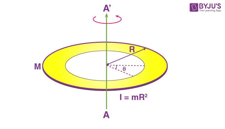
moment of inertia of the ring mass or angular acceleration when torque is applied
https://www.vedantu.com/question-answer … 7a380eee5e
https://byjus.com/jee/moment-of-inertia-of-a-ring/
https://en.wikipedia.org/wiki/List_of_m … of_inertia
https://farside.ph.utexas.edu/teaching/ … de103.html
Offline
Like button can go here